DTC P2135 THROTTLE/PEDAL POSITION SENSOR/SWITCH “A” / “B” VOLTAGE RATIONALITY
|
|
DTC P2135 THROTTLE/PEDAL POSITION
SENSOR/SWITCH “A” / “B” VOLTAGE
RATIONALITY
|
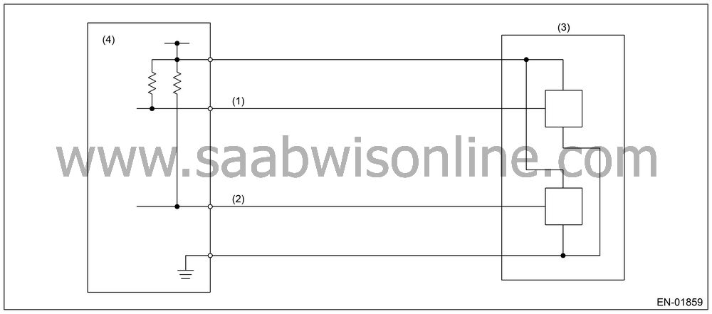
Judge NG when the signal level of throttle
position sensor 1 is different from the throttle position sensor
2.

(1)
|
Throttle
position sensor 1 signal.
|
(3)
|
Throttle
position sensor
|
|
|
(2)
|
Throttle
position sensor 2 signal.
|
(4)
|
Engine
control module (ECM)
|
|
|
|
Secondary
Parameters
|
Enable
Conditions
|
Ignition
switch
|
ON
|
Always perform the diagnosis continuously.
Judge OK and clear the NG when the malfunction
criteria below are completed.
Judgment
Value
|
Malfunction
Criteria
|
Threshold
Value
|
Signal
difference between two sensors
|
≤ 4.25 °
|
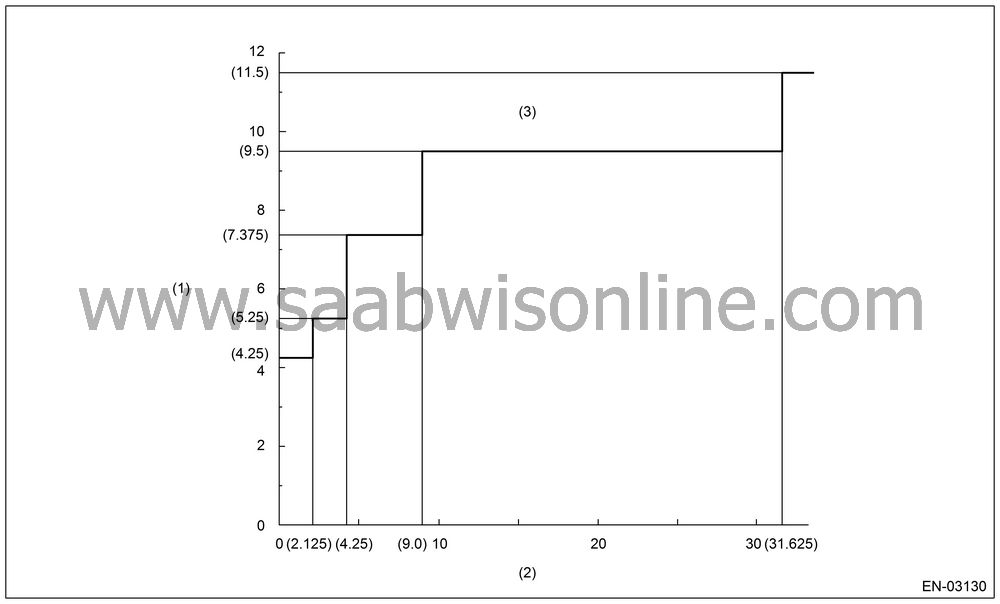
Details of Judgment
Value

(1)
|
Sensor
output difference (°)
|
(2)
|
Throttle position sensor 1 opening angle (°)
|
(3)
|
NG area
|
|
|
|
|
|
|
Time Needed for Diagnosis:
212
milliseconds (NG judgment) 24 milliseconds (OK judgment)
Malfunction Indicator
Light Illumination:
Illuminates as soon as malfunction occurs.
|
•
|
When the OK idling cycle was completed 40 times
in a row
|
|
•
|
When “Clear Memory” was
performed (Only engine stop)
|
|
MALFUNCTION
INDICATOR LIGHT CLEAR CONDITION
|
|
•
|
When the OK driving cycle was completed 3 times
in a row
|
|
•
|
When “Clear Memory” was
performed (Only engine stop)
|
Stop the continuity to electronic control
throttle motor. (Fix the throttle opening angle to 6°.)
|
ECM OPERATION
AT DTC SETTING
|
Memorize the freeze frame data. (For test
mode $02)


