OPERATION
| OPERATION |
| HOW TO USE Vehicle Diagnostic Interface |
Prepare the Vehicle Diagnostic Interface kit.

Connect the diagnosis cable to Vehicle Diagnostic Interface.
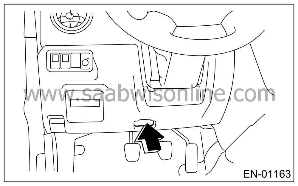
Connect the Vehicle Diagnostic Interface to data link connector.
Data link connector is located in the lower portion of instrument panel (on the driver’s side).

| Important | ||
|
Do not connect the scan tools except for Vehicle Diagnostic Interface and OBD-II general scan tool. |
||
Turn the ignition switch to ON (engine OFF), and start the Vehicle Diagnostic Interface.
Using the Vehicle Diagnostic Interface, call up the DTC and various data, and then record them.
| READ DIAGNOSTIC TROUBLE CODE (DTC) FOR ENGINE. (NORMAL MODE) |
Refer to Read Diagnostic Trouble Code (DTC) for information about how to indicate DTC.

| READ DIAGNOSTIC TROUBLE CODE (DTC) FOR ENGINE. (OBD MODE) |
Refer to Read Diagnostic Trouble Code (DTC) for information about how to indicate DTC.

| READ CURRENT DATA FOR ENGINE. (NORMAL MODE) |
On the «Main Menu» display screen, select the {Each System Check}.
On the «System Selection Menu» display screen, select the {Engine Control System}.
Select the {OK} after the information of engine type is displayed.
On the «Engine Diagnosis» display screen, select the {Current Data Display & Save}.
On the «Data Display Menu» display screen, select the {Data Display}.
Using the scroll key, move the display screen up or down until desired data is shown.
| • |
A list of the support data is shown in the
following table.
|
|||||||||||||||||||||||||||||||||||||||||||||||||||||||||||||||||||||||||||||||||||||||||||||||||||||||||||||||||||||||||||||||||||||||||||||||||||||||||||||||||||||||||||||||||||||||||||||||||
| READ CURRENT DATA FOR ENGINE. (OBD MODE) |
On the «Main Menu» display screen, select the {Each System Check}.
On the «System Selection Menu» display screen, select the {Engine Control System}.
Select the {OK} after the information of engine type is displayed.
On the «Engine Diagnosis» display screen, select the {OBD System}.
On the «OBD Menu» display screen, select the {Current Data Display & Save}.
On the «Data Display Menu» display screen, select the {Data Display}.
Using the scroll key, move the display screen up or down until desired data is shown.
| • |
A list of the support data is shown in the
following table.
|
||||||||||||||||||||||||||||||||||||||||||||||||||||||||||||||||||||||||||||||||||||||||||||||||||||||||||||||||
| READ FREEZE FRAME DATA FOR ENGINE. (OBD MODE) |
On the «Main Menu» display screen, select the {Each System Check}.
On the «System Selection Menu» display screen, select the {Engine Control System}.
Select the {OK} after the information of engine type is displayed.
On the «Engine Diagnosis» display screen, select the {OBD System}.
On the «OBD Menu» display screen, select the {Freeze Frame Data}.
| • |
A list of the support data is shown in the
following table.
|
|||||||||||||||||||||||||||||||||||||||||||||||||
| LED OPERATION MODE FOR ENGINE |
On the «Main Menu» display screen, select the {Each System Check}.
On the «System Selection Menu» display screen, select the {Engine Control System}.
Select the {OK} after the information of engine type is displayed.
On the «Engine Diagnosis» display screen, select the {Current Data Display & Save}.
On the «Data Display Menu» display screen, select the {Data & LED Display}.
Using the scroll key, move the display screen up or down until the desired data is shown.
| • |
A list of the support data is shown in the
following table.
|
|||||||||||||||||||||||||||||||||||||||||||||||||||||||||||||||||||||||||||||||||||||||||||||||||||||||||||||||||||||||
| READ CURRENT DATA FOR AT |
On the «Main Menu» display screen, select the {Each System Check}.
On the «System Selection Menu» display screen, select the {Transmission Control System}.
Select the {OK} after the information of transmission type is displayed.
On the «Transmission Diagnosis» display screen, select the {Current Data Display & Save}.
On the «Data Display Menu» display screen, select the {Data Display}.
Using the scroll key, move the display screen up or down until desired data is shown.
| • |
A list of the support data is shown in the
following table.
|
|||||||||||||||||||||||||||||||||||||||||||||||||||||||||||||||||||||||||||||||||||||||||||||||||||||||


