ADJUSTMENT
| ADJUSTMENT |
| Important | ||
|
Adjustment of valve clearance should be performed while engine is cold. |
||
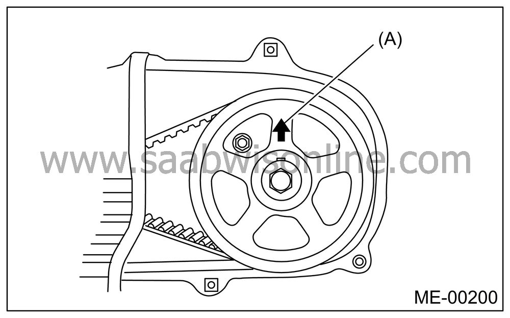
Set #1 cylinder piston to top dead center of compression stroke by rotating the crank pulley clockwise using the socket wrench.

| Note | ||
|
When the arrow mark (A) on cam sprocket (LH) comes exactly to the top, #1 cylinder piston is brought to the top dead center of compression stroke. |
Adjust the #1 cylinder valve clearance.
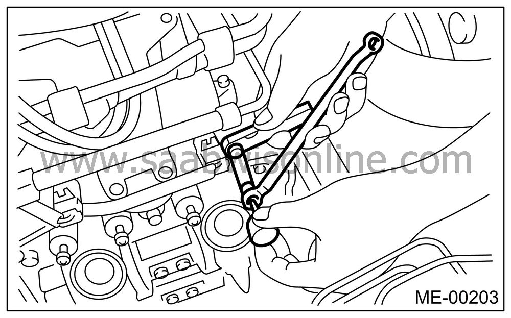
Loosen the valve rocker nut and screw.
Place a suitable thickness gauge.
While noting the valve clearance, tighten the valve rocker adjusting screw.
When the specified valve clearance is obtained, tighten the valve rocker nut.
Tightening torque:
10 Nm (1.0 kgf-m, 7.2 ft-lb)
| Important | ||
| • |
Insert the thickness gauge in
as horizontally as possible with respect to the valve stem end face.
|
|
| • |
Adjust the exhaust valve clearances while lifting-up
the vehicle.
|
|
Valve clearance
Intake:
0.20±0.04 mm (0.0079±0.0016 in)Exhaust:
0.25±0.04 mm (0.0098±0.0016 in)
| Note | ||
| • |
Be sure to set the cylinder pistons to their respective
top dead centers on compression stroke before adjusting valve clearances.
|
|
| • |
By rotating the crank pulley clockwise every 180° from
the state that #1 cylinder piston is on the top dead center
of compression stroke, #3, #2 and #4 cylinder
pistons come to the top dead center of compression stroke in this
order.
|
|
Ensure the valve clearances of each cylinder are within specifications. If necessary, readjust the valve clearances.


