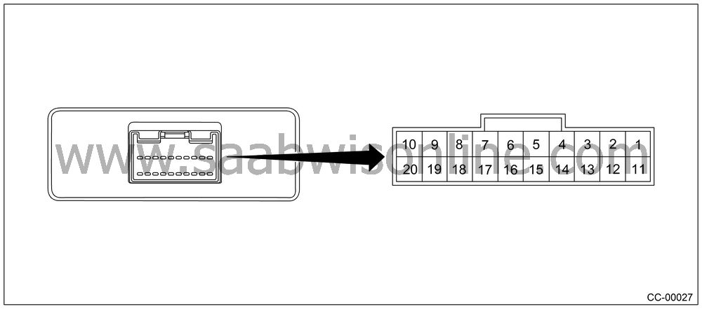
|
Content
|
Terminal
No.
|
Measuring
condition and I/O signal (ignition switch ON and engine
idling)
|
Cruise
indicator light
|
1
|
|
•
|
Battery voltage
is present when main switch is turned OFF.
|
|
•
|
“0 V” voltage is present when main
switch is turned ON.
|
|
Cruise
set indicator light
|
3
|
|
•
|
“0
V” voltage is present when cruise control is set and operated.
|
|
•
|
Battery voltage is present when cruise control is not
set and not operated.
|
|
Inhibitor
switch (AT model)
|
4
|
|
•
|
Battery voltage
is present when selector lever is other than “P” or “N” position.
|
|
•
|
“0 V” voltage is present when selector
lever is set to “P” or “N” position.
|
|
Motor B
|
5
|
|
•
|
ON-and-OFF
(“0 V”-and-battery voltage) operation is alternately
repeated while cruise control is operating.
|
|
•
|
“0 V” voltage is present when main
switch is turned OFF.
|
|
Ground
|
6
|
—
|
Motor A
|
7
|
|
•
|
ON-and-OFF
(“0 V”-and-battery voltage) operation is alternately
repeated while cruise control is operating.
|
|
•
|
“0 V” voltage is present when main
switch is turned OFF.
|
|
RES/ACC
switch
|
9
|
|
•
|
Battery voltage
is present when switch is turned to RES/ACC position.
|
|
•
|
“0 V” voltage is present when switch
is released.
|
|
SET/COAST
switch
|
10
|
|
•
|
Battery voltage
is present when switch is turned to SET/COAST position.
|
|
•
|
“0 V” voltage is present when switch
is released.
|
|
Main power
supply
|
11
|
|
•
|
Battery voltage
is present when ignition switch is turned ON.
|
|
•
|
“0 V” voltage is present when ignition
switch is turned OFF.
|
|
Ignition
switch
|
12
|
|
•
|
Battery voltage
is present when ignition switch is turned ON.
|
|
•
|
“0 V” voltage is present when ignition
switch is turned OFF.
|
|
Motor C
|
13
|
|
•
|
ON-and-OFF
(“0 V”-and-battery voltage) operation is alternately
repeated while cruise control is operating.
|
|
•
|
“0 V” voltage is present when main
switch is turned OFF.
|
|
Motor clutch
|
14
|
|
•
|
ON-and-OFF
(“0 V”-and-battery voltage) operation is alternately
repeated while cruise control is operating.
|
|
•
|
“0 V” voltage is present when vehicle
is stopped.
|
|
Curise
control main switch
|
15
|
|
•
|
Battery voltage
is present while the cruise control main switch is depressed.
|
|
•
|
“0 V” voltage is present when curise
control main switch is turned OFF.
|
|
Brake switch
|
16
|
Leave clutch
pedal released (MT model), while curise control main switch is turned
ON.
Then check that;
|
•
|
Battery
voltage is present when brake pedal is released.
|
|
•
|
“0” volt is present when brake pedal
is depressed.
|
Additionally for MT model, release the brake pedal with the
curise control main switch ON.
Then check that;
|
•
|
Battery
voltage is present when clutch pedal is released.
|
|
•
|
“0” volt is present when clutch pedal
is depressed.
|
|
Data link
connector
|
17
|
—
|
Data link
connector
|
18
|
—
|
Vehicle
speed sensor (MT model)
TCM (AT model)
|
19
|
Lift-up
the vehicle until all four wheels are raised off ground, and then
rotate any wheel manually.
Approx. “5” and “0” volt
pulse signals are alternately input to cruise control module.
|
Stop light
switch
|
20
|
Turn ignition
switch to OFF.
Then check that;
|
•
|
Battery
voltage is present when brake pedal is depressed.
|
|
•
|
“0” volt is present when brake pedal
is released.
|
|
NOTE:
Voltage at terminals 5, 7, 13 and 14 cannot be checked unless
vehicle is driving by cruise control operation.
|


