INSPECTION
| INSPECTION |
| DIODE |
| Important | ||
|
Never use a mega tester (designed for reading high voltage) or any other similar instrument for this test; otherwise, the diodes may be damaged. |
||
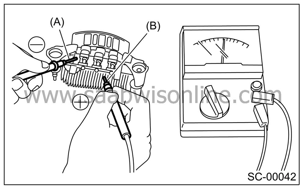
Checking positive diode
Check for continuity between the diode lead and positive side heat sink. The positive diode is in good condition if resistance is 1 Ω or less only in the direction from the diode lead to heat sink.
|
(A)
|
Diode lead
|
|
(B)
|
Heat sink
(positive side)
|
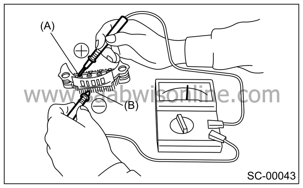
Checking negative diode
Check for continuity between the negative side heat sink and diode lead. The negative diode is in good condition if resistance is 1 Ω or less only in the direction from the heat sink to diode lead.
|
(A)
|
Diode lead
|
|
(B)
|
Heat sink
(negative side)
|
| ROTOR |
Slip ring surface
Inspect the slip rings for contamination or any roughness on the sliding surface. Repair the slip ring surface using a lathe or sand paper.
Slip ring outer diameter
Measure the slip ring outer diameter. If the slip ring is worn, replace the rotor assembly.
Slip ring outer diameter:
Standard
22.7 mm (0.894 in)Limit
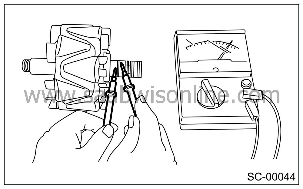
22.1 mm (0.870 in)Continuity test
Check the resistance between slip rings using circuit tester.
If the resistance is not within the specified range, replace the rotor assembly.
Specified resistance:
Approx. 1.8 — 2.2 Ω
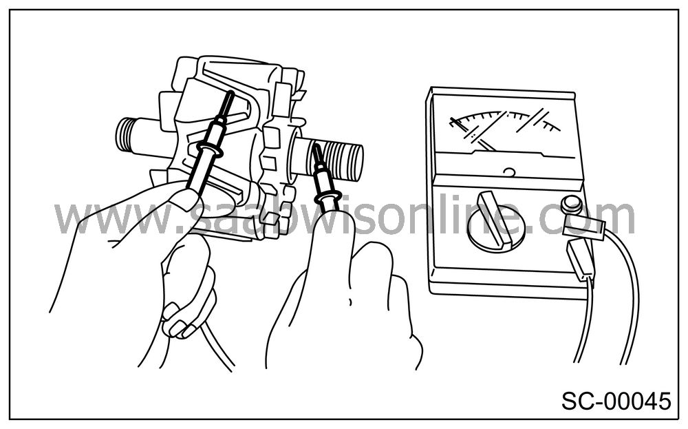
Insulation test
Check the continuity between slip ring and rotor core or shaft. If resistance is 1 Ω or less, the rotor coil is grounded, and so replace the rotor assembly.
Ball bearing (rear side)
Check the rear ball bearing. Replace if it is noisy or if the rotor does not turn smoothly.
| STATOR |
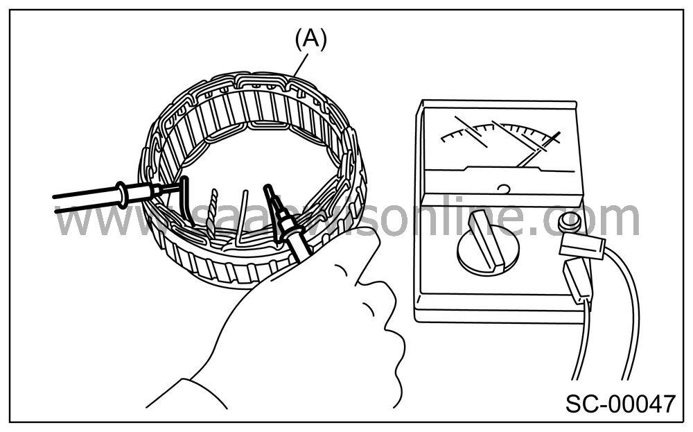
Continuity test
Inspect the stator coil for continuity between each end of the lead wires. If resistance is 1 MΩ or more, the lead wire is broken, and so replace the stator assembly.
|
(A)
|
Stator
|
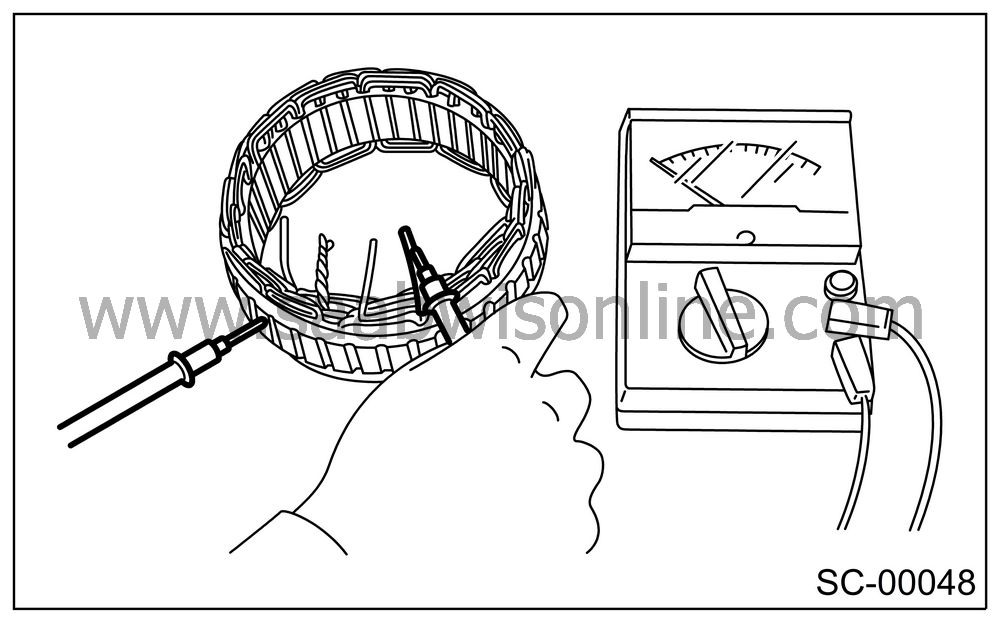
Insulation test
Inspect the stator coil for continuity between stator core and each end of lead wire. If resistance is 1 Ω or less, the stator coil is grounded, and so replace the stator assembly.
| BRUSH |
Measure the length of each brush. If wear exceeds the service limit, replace the brush. Each brush has the service limit mark (A) on it.
Brush length:
Standard
18.5 mm (0.728 in)Service limit
5.0 mm (0.197 in)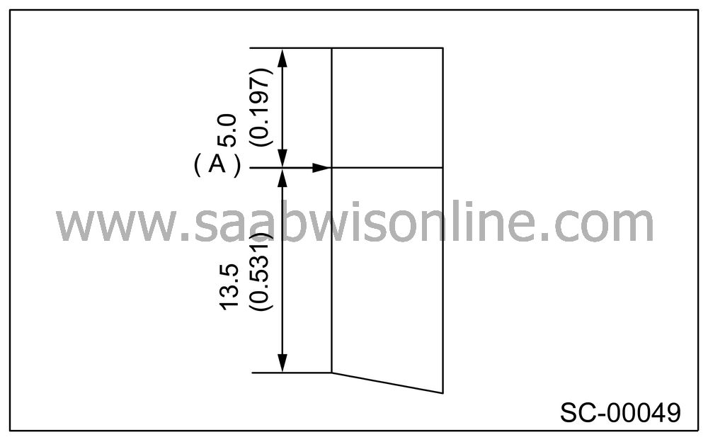
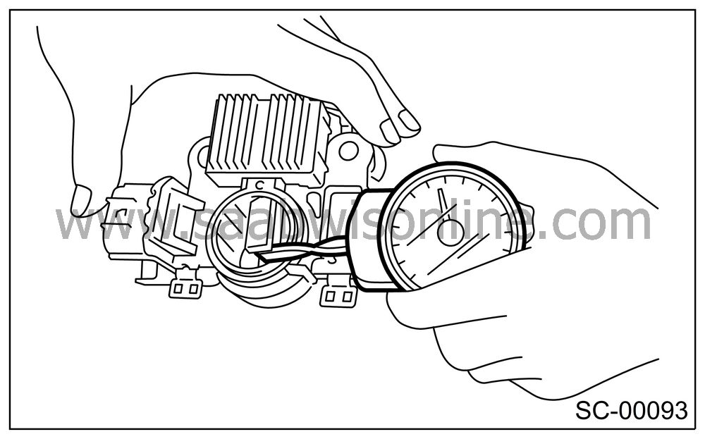
Checking brush spring for proper pressure
Using a spring pressure indicator, push the brush into the brush holder until its tip protrudes 2 mm (0.08 in). Then measure the pressure of brush spring. If the pressure is less than 2.648 N (270 g, 9.52 oz), replace the brush spring with a new one. The new spring must have a pressure of 4.609 to 5.786 N (470 to 590 g, 16.58 to 20.810 oz).
| BEARING (FRONT SIDE) |
Check the front ball bearing. If the resistance is felt while rotating, or if abnormal noise is heard, replace the ball bearing.


