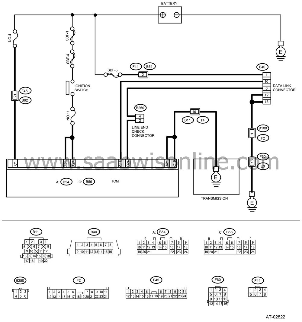
COMMUNICATION FOR INITIALIZING IMPOSSIBLE
| COMMUNICATION FOR INITIALIZING IMPOSSIBLE |
DIAGNOSIS:
Faulty harness connector
TROUBLE SYMPTOM:
Vehicle Diagnostic Interface communication failure
WIRING DIAGRAM:

CHECK Vehicle Diagnostic Interface POWER SUPPLY CIRCUIT.
Measure the voltage between data link connector and chassis ground.Connector & terminal
(B40) No. 1 (+) — Chassis ground (−):
Is the voltage more than 10 V?
| Yes |
| No |
Repair the harness and connector between battery and data link connector, and poor contact in coupling connector.
CHECK Vehicle Diagnostic Interface GROUND CIRCUIT.
Measure the resistance of harness between data link connector and chassis ground.Connector & terminal
(B40) No. 12 — Chassis ground:
(B40) No. 13 — Chassis ground:
Is the resistance less than 1 Ω?
| Yes |
| No |
Repair the open circuit in harness between data link connector and ground terminal, and poor contact in coupling connector.
CHECK COMMUNICATION OF Vehicle Diagnostic Interface.
Turn the ignition switch to ON.Using the Vehicle Diagnostic Interface, check whether communication to engine systems can be executed normally.
Are the name and year of system displayed on Vehicle Diagnostic Interface?
| Yes |
| No |
CHECK COMMUNICATION OF Vehicle Diagnostic Interface.
Turn the ignition switch to OFF.Disconnect the TCM connector.
Check whether communication to engine systems can be executed normally.
Are the name and year of system displayed on Vehicle Diagnostic Interface?
| Yes |
| No |
CHECK COMMUNICATION OF Vehicle Diagnostic Interface.
Turn the ignition switch to OFF.Connect the TCM connector.
Disconnect the ECM connector.
Check whether communication to transmission systems can be executed normally.
Are the name and year of system displayed on Vehicle Diagnostic Interface?
| Yes |
Inspect the ECM.
| No |
CHECK HARNESS CONNECTOR BETWEEN EACH CONTROL MODULE AND DATA LINK CONNECTOR.
Turn the ignition switch to OFF.Disconnect the TCM, ECM, ABSCM&H/U, cruise control module and immobilizer control module connectors.
Measure the resistance between TCM connector and chassis ground.
Connector & terminal
(B40) No. 10 — Chassis ground:
(B40) No. 6 — Chassis ground:
Is the resistance more than 1 MΩ?
| Yes |
| No |
Repair the harness and connector between each control module and data link connector.
CHECK OUTPUT SIGNAL FOR TCM.
Turn the ignition switch to ON.Measure the voltage between TCM and chassis ground.
Connector & terminal
(B40) No. 10 (+) — Chassis ground (−):
(B40) No. 6 (+) — Chassis ground (−):
Is the voltage more than 1 V?
| Yes |
Repair the harness and connector between each control module and data link connector.
| No |
CHECK HARNESS/CONNECTOR BETWEEN TCM AND DATA LINK CONNECTOR.
Measure the resistance between TCM connector and data link connector.Connector & terminal
(B56) No. 15 — (B40) No. 10:
Is the resistance less than 0.5 Ω?
| Yes |
| No |
Repair the harness and connector between TCM and data link connector.
CHECK HARNESS/CONNECTOR BETWEEN TCM AND DATA LINK CONNECTOR.
Measure the resistance between TCM and data link connector.Connector & terminal
(B56) No. 24 — (B40) No. 6:
Is the resistance more than 1 MΩ?
| Yes |
Repair the open circuit in harness between TCM and data link connector.
| No |
CHECK INSTALLATION OF TCM CONNECTOR.
Turn the ignition switch to OFF.Is the TCM connector inserted into TCM?
| Yes |
| No |
Insert the TCM connector into TCM.
CHECK POOR CONTACT IN CONNECTORS.
Is there poor contact in control module and data link connector?
| Yes |
Repair the poor contact.
| No |


