DTC P0715 INPUT/TURBINE SPEED SENSOR CIRCUIT
| DTC P0715 INPUT/TURBINE SPEED SENSOR CIRCUIT |
DIAGNOSIS:
The input signal circuit of TCM is open or shorted.
TROUBLE SYMPTOM:
Excessive shift shock.
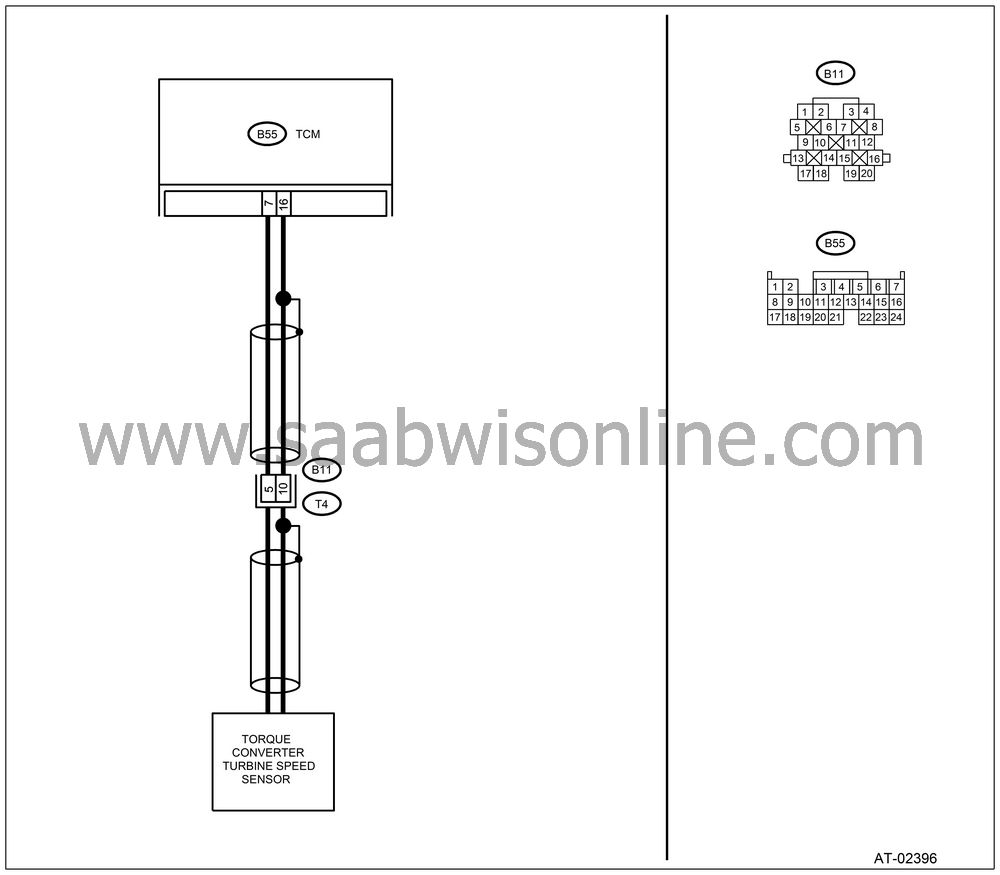
WIRING DIAGRAM:

CHECK TORQUE CONVERTER TURBINE SPEED SENSOR.
Turn the ignition switch to OFF.Disconnect the connector from transmission.
Measure the resistance between transmission connector receptacle’s terminals.
Connector & terminal
(T4) No. 5 — No. 10:
Is the resistance 450 — 650 Ω?
| Yes |
| No |
Replace the torque converter turbine
speed sensor.

CHECK HARNESS CONNECTOR BETWEEN TCM AND TRANSMISSION.
Disconnect the connector from TCM.Measure the resistance of harness between TCM and transmission connector.
Connector & terminal
(B55) No. 7 — (B11) No. 5:
Is the resistance less than 1 Ω?
| Yes |
| No |
Repair the open circuit in harness between TCM and transmission connector.
CHECK HARNESS CONNECTOR BETWEEN TCM AND TRANSMISSION.
Measure the resistance of harness between TCM and transmission connector.Connector & terminal
(B55) No. 16 — (B11) No. 10:
Is the resistance less than 1 Ω?
| Yes |
| No |
Repair the open circuit in harness between TCM and transmission connector, and poor contact in coupling connector.
CHECK HARNESS CONNECTOR BETWEEN TCM AND TRANSMISSION.
Measure the resistance of harness between TCM and chassis ground.Connector & terminal
(B55) No. 16 — Chassis ground:
Is the resistance more than 1 MΩ?
| Yes |
| No |
Repair the short circuit in harness between TCM and transmission connector.
CHECK HARNESS CONNECTOR BETWEEN TCM AND TRANSMISSION.
Measure the resistance of harness between TCM and chassis ground.Connector & terminal
(B55) No. 7 — Chassis ground:
Is the resistance more than 1 MΩ?
| Yes |
| No |
Repair the short circuit in harness between TCM and transmission connector, and poor contact in coupling connector.
CHECK INPUT SIGNAL FOR TCM USING Vehicle Diagnostic Interface.
Connect the connectors to TCM and transmission.Connect the Vehicle Diagnostic Interface to data link connector.
Turn the ignition switch to ON and turn Vehicle Diagnostic Interface switch to ON.
Start the engine.
Move the select lever to “P” or “N” range.
Read the data of turbine speed using Vehicle Diagnostic Interface.
| • |
Compare
the tachometer reading with Vehicle
Diagnostic Interface indications.
|
|
Is the revolution value same as the tachometer reading shown on the combination meter?
| Yes |
Even if the POWER indicator blinks, the circuit has returned to a normal condition at this time. A temporary poor contact of the connector or harness may be the cause. Repair the harness or connector in TCM and transmission.
| No |
CHECK POOR CONTACT.
Is there poor contact in torque converter turbine speed sensor circuit?
| Yes |
Repair the poor contact.
| No |


