ASSEMBLY
| ASSEMBLY |
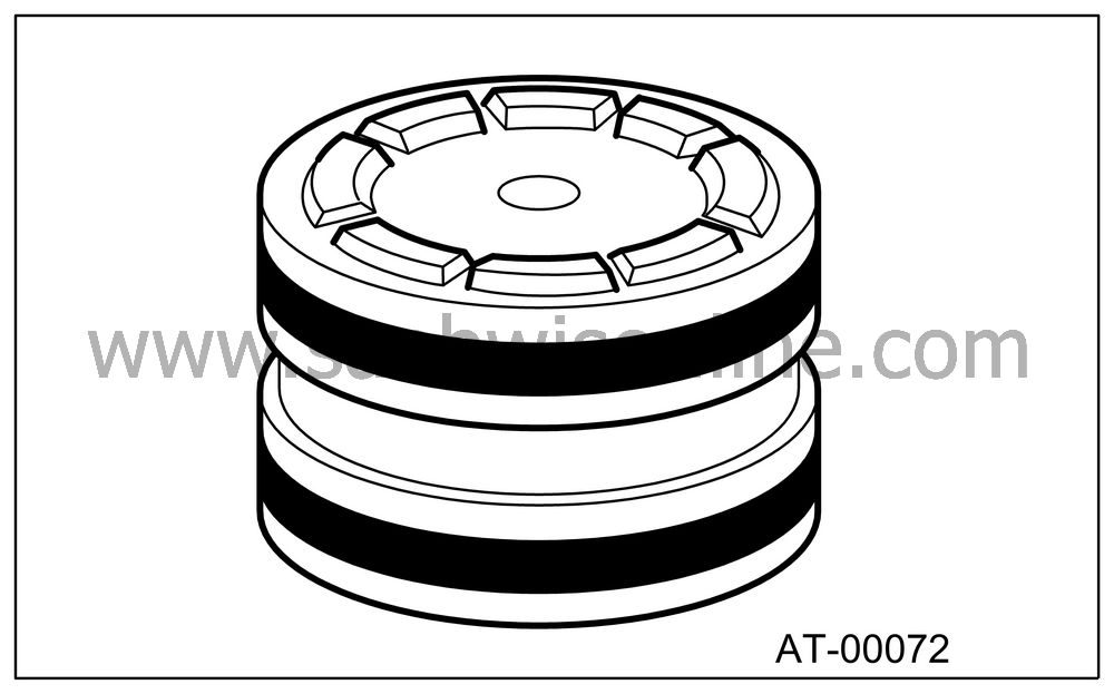
Insert the piston fully into upper valve body.
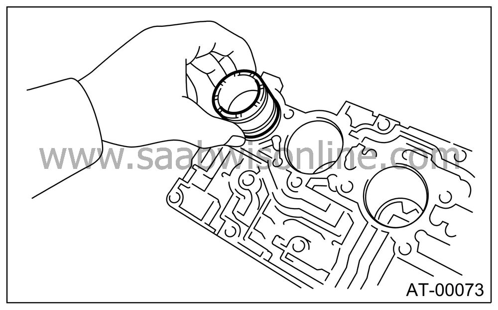
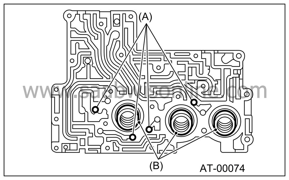
Install the spring and four steel balls to specified positions of upper valve body.
|
(A)
|
Steel ball
|
|
(B)
|
Spring
|
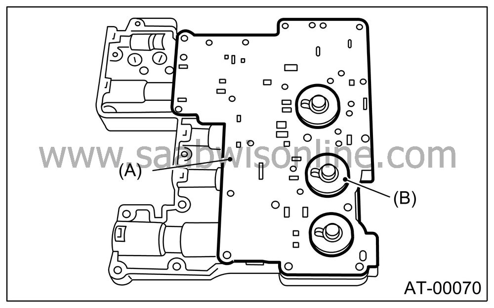
Align the hole in side plate with the hole in separator plate, and then install support plate and upper separator plate to middle valve body.
Tightening torque:
8 Nm (0.8 kgf-m, 5.8 ft-lb)
|
(A)
|
Upper separator
plate
|
|
(B)
|
Side plate
|
Insert six steel balls in their proper positions to middle valve body.
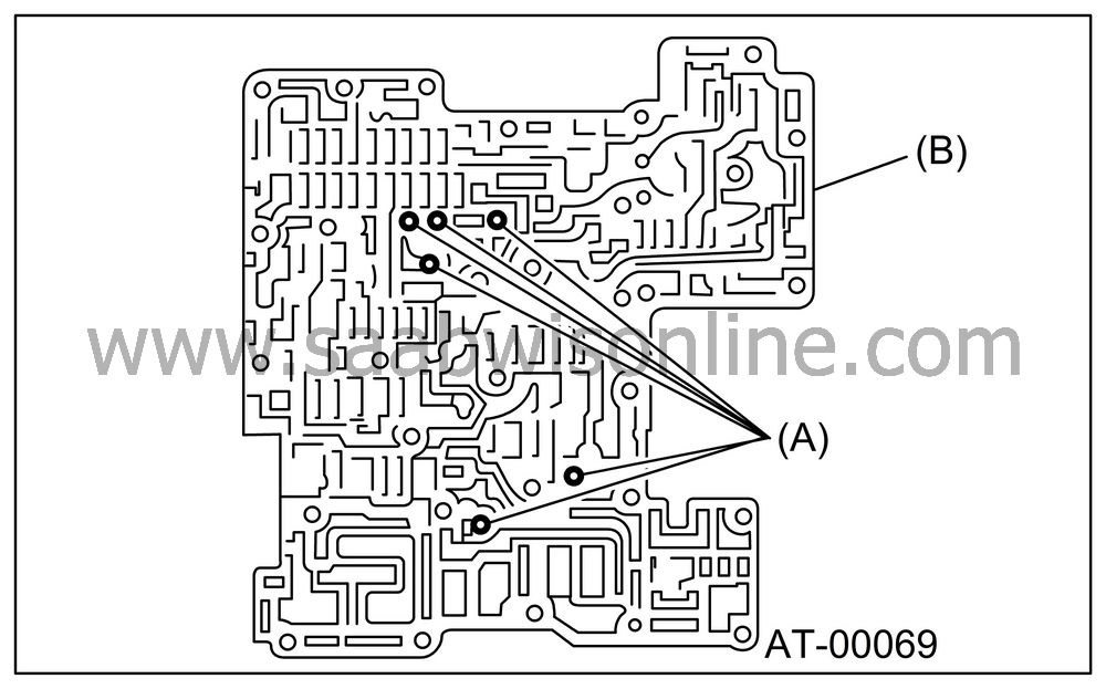
|
(A)
|
Steel ball
|
|
(B)
|
Middle
valve body
|
Install three filters to lower valve body.
| Note | ||
|
Pay attention to the location of filters. |
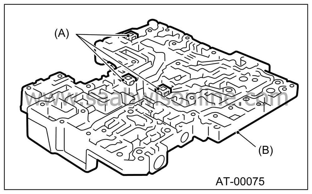
|
(A)
|
Strainer
|
|
(B)
|
Lower valve
body
|
Install the lower separate plate to lower valve body.
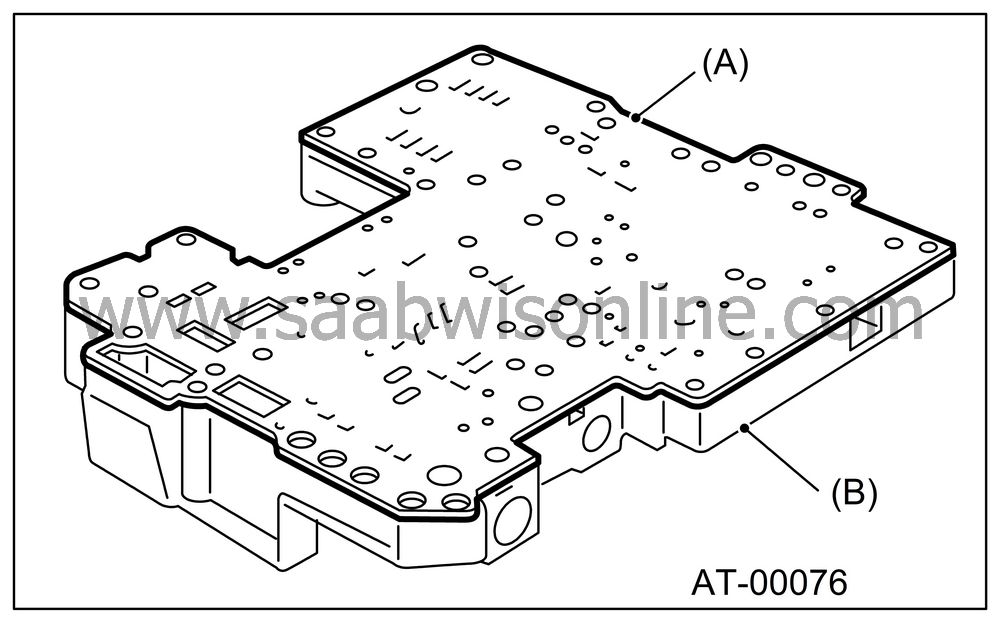
|
(A)
|
Lower separator
plate
|
|
(B)
|
Lower valve
body
|
Temporarily assemble the valve body.
| Note | ||
|
Be careful not to drop the middle valve body and upper body interior steel ball, or the lower body filter. |
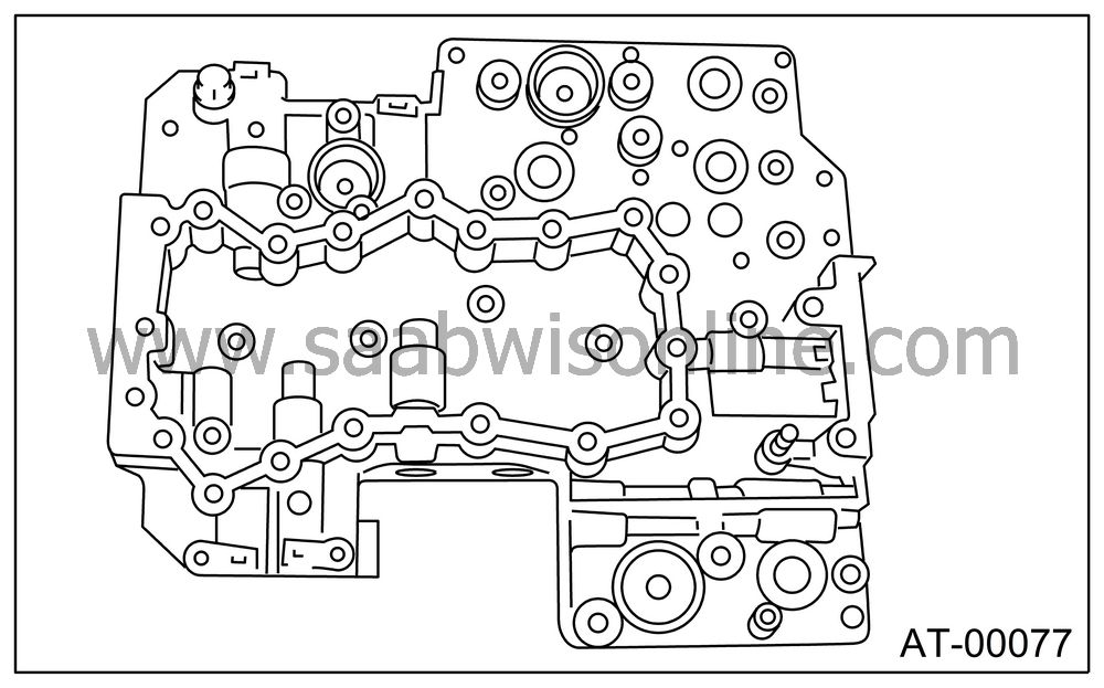
Tighten the bolts and nuts.
| Note | ||
|
Install the bolts (D) from upper valve body side. |
Tightening torque:
8 Nm (0.8 kgf-m, 5.8 ft-lb)
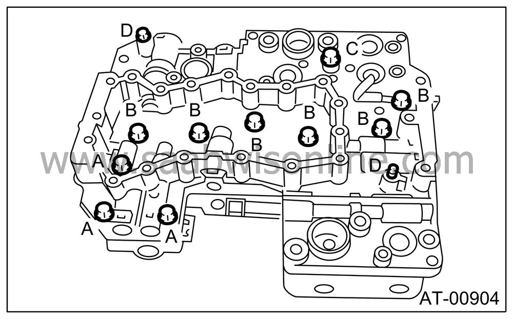
|
Bolt length
mm (in)
|
|
|
(A)
|
40 (1.57)
|
|
(B)
|
62 (2.44)
|
|
(C)
|
73 (2.87)
|
|
(D)
|
79 (3.11)
|
Install the sensor, solenoids and duty solenoids to specified positions.
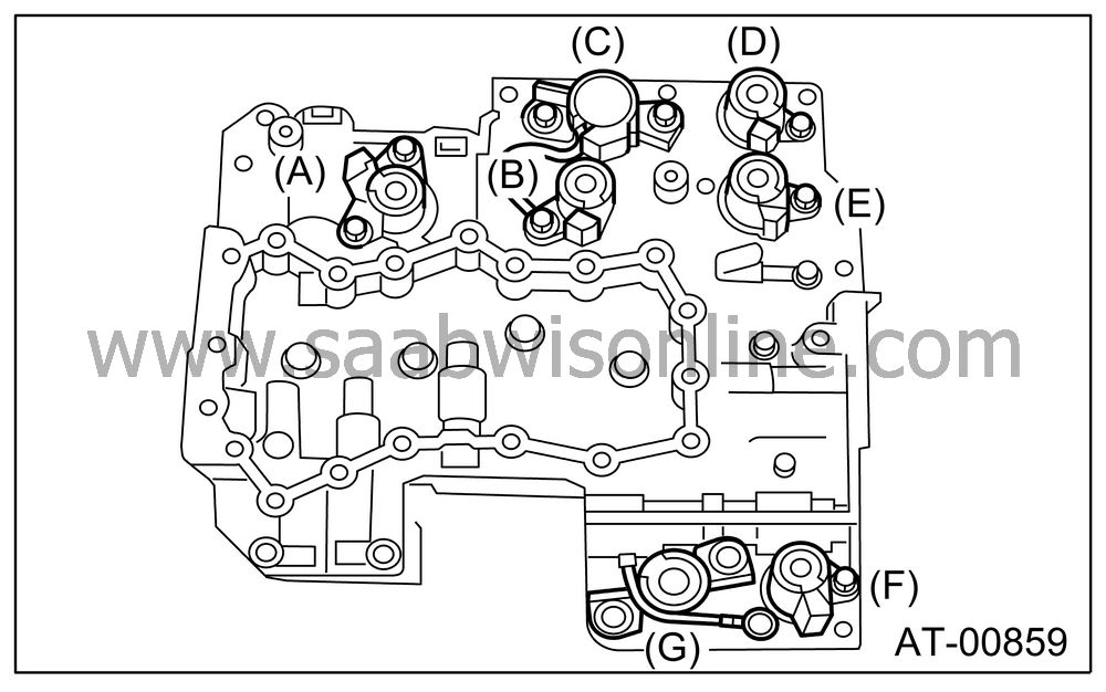
|
(A)
|
Lock-up
duty solenoid (Blue)
|
|
(B)
|
Low clutch
timing solenoid (Gray)
|
|
(C)
|
Line pressure
duty solenoid (Red)
|
|
(D)
|
Shift solenoid 2
(Yellow)
|
|
(E)
|
Shift solenoid 1
(Green)
|
|
(F)
|
2-4 brake
timing solenoid (Black)
|
|
(G)
|
2-4 brake
duty solenoid (Red)
|
Tighten the bolts.
Tightening torque:
8 Nm (0.8 kgf-m, 5.8 ft-lb)
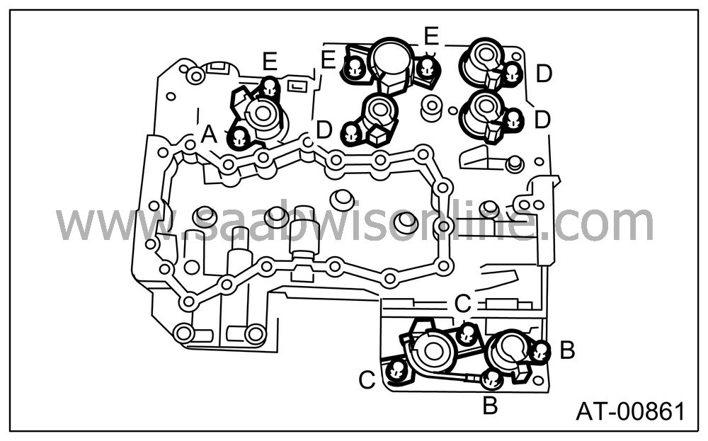
|
Bolt length
mm (in)
|
|
|
(A)
|
12 (0.47)
|
|
(B)
|
40 (1.57)
|
|
(C)
|
45 (1.77)
|
|
(D)
|
62 (2.44)
|
|
(E)
|
73 (2.87)
|
Install oil strainer to lower valve body.
Tightening torque:
8 Nm (0.8 kgf-m, 5.8 ft-lb)
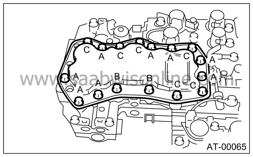
|
Bolt length
mm (in)
|
|
|
(A)
|
12 (0.47)
|
|
(B)
|
62 (2.44)
|
|
(C)
|
81 (3.19)
|

