ADJUSTMENT
| ADJUSTMENT |
Remove drive plate and driven plate from center differential carrier.
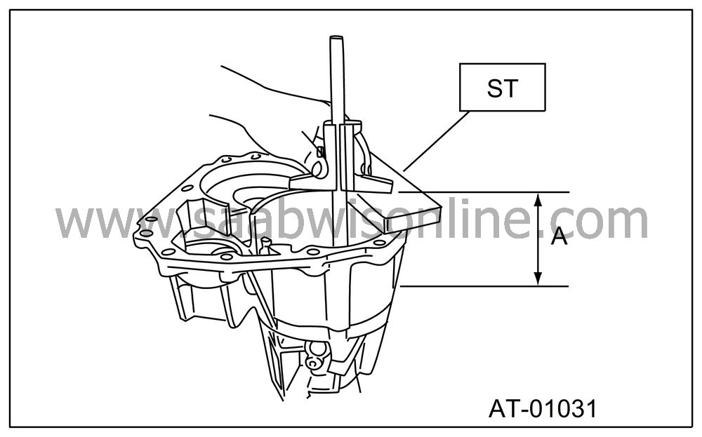
Using the special tool, measure distance “A” from extension case joining surface to multi-plate clutch (LSD) piston.
ST 32005073 GAUGE

|
A:
|
Measured
value
|
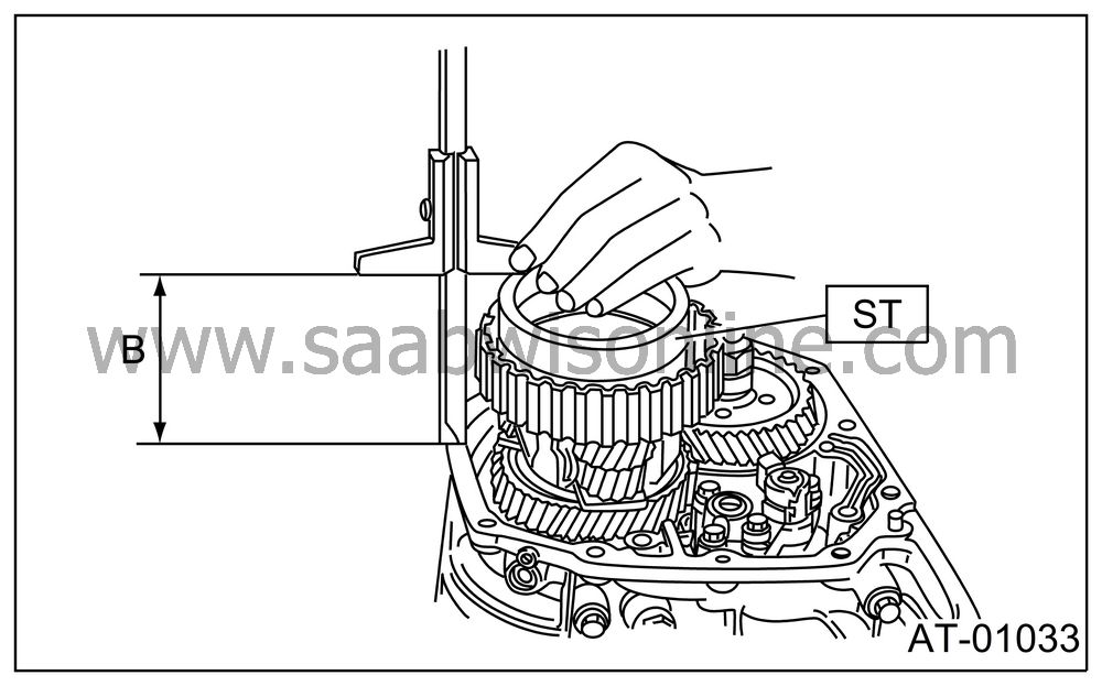
Using ST, measure height “B” from transmission case joining edge to center differential clutch drum edge.
ST 32005076 GAUGE

|
B:
|
Measured
value
|
Calculation formula
T = A − B + 0.45 mm
[T = A − B + 0.0177 in]
| Note | ||
| • |
Calculation formula for “T” is applied
when measuring using ST (32005073
GAUGE, 32005076 GAUGE). When not using
ST, apply
T = (A − α + 0.45 mm) − (B − β) [T = (A − α + 0.0177 in) − (B − β)]. T: Thrust needle bearing thickness A: Distance from end of extension case to end of reduction drive shaft B: Distance from end of transmission case to end of rear drive shaft α: Collar thickness used when measuring “A” β: Collar thickness used when measuring “B” 0.45: Gasket thickness (mm) |
|
| • |
Measure multi-plate clutch (LSD) driven and drive plate
thickness to find the clearance between measurement value and “T”.
|
|
Standard value:
0.2 — 0.6 mm (0.008 — 0.024 in)
Limit value:
1.6 mm (0.063 in)
If outside the standard value, replace the plate set (drive and driven plate). Select a multi-plate clutch (LSD) piston side adjustment plate that will bring clearance within the standard value.
|
Obtainable driven plate
|
|
|
Part
No.
|
Thickness
mm (in)
|
|
32006533
|
1.6 (0.063)
|
|
32006534
|
2.0 (0.079)
|
|
32006535
|
2.4 (0.094)
|
|
32006536
|
2.8 (0.110)
|


