ADJUSTMENT
| ADJUSTMENT |
| MPT MODEL |
Measure distance “A” from end of extension case and rear drive shaft with ST.
ST 32005073 GAUGE
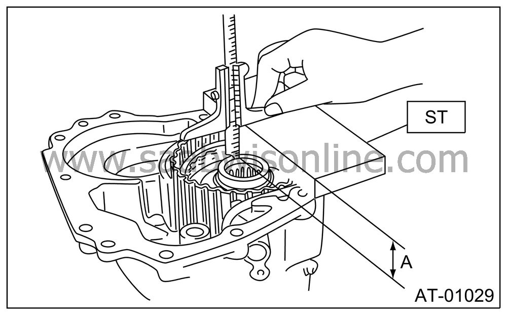
|
A:
|
Measured
value
|
Measure the distance “B” from the transmission case mating surface to the reduction drive gear end surface with ST1 and ST2.
ST1 32005073 GAUGE
ST2 32005133 GAUGE
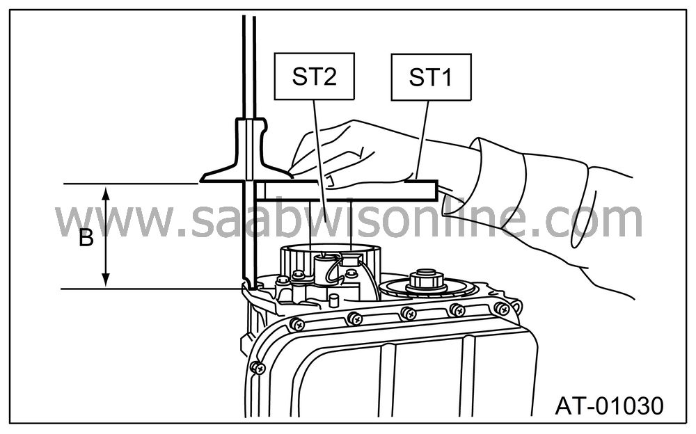
|
B:
|
Measured
value
|
Calculation formula:
| Note | ||
| • |
Calculate “T”:
T = A − B + 35.4 mm [T = A − B + 1.3937 in] T: Thrust needle bearing thickness A: Distance from end of extension case to end of rear drive shaft B: Distance from end of transmission case to end of reduction drive gear Example: When, A = 33.6 mm (1.3228 in), B = 65.05 mm (2.5610 in) T = 33.6 − 65.05 + 35.4 = 3.95 [T = 1.3228 − 2.5610 + 1.3937 = 0.1555] After calculation, the valve of “H” becomes 3.95 mm (0.1555 in), therefore select bearing thickness of 3.8 mm (0.150 in). |
|
| • |
Calculation formula for “T” is applied
when measuring using ST (32005073
GAUGE, 32005133 GAUGE). When not using
ST, apply
T = (A − α + 0.45 mm) − (B − β) − H [T = (A − α + 0.0177 in) − (B − β) − H]. T: Thrust needle bearing thickness A: Distance from end of extension case to end of reduction drive shaft B: Distance from end of transmission case to end of rear drive shaft α: Collar thickness used when measuring “A” β: Collar thickness used when measuring “B” 0.45 (0.0177): Gasket thickness (mm (in)) H: Shim clearance |
|
|
Thrust needle bearing
|
|
|
Part
No.
|
Thickness
mm (in)
|
|
32008433
|
3.8 (0.150)
|
|
32008426
|
4.0 (0.157)
|
|
32008427
|
4.2 (0.165)
|
|
32008428
|
4.4 (0.173)
|
|
32008429
|
4.6 (0.181)
|
|
32008430
|
4.8 (0.189)
|
|
32008431
|
5.0 (0.197)
|
| VTD MODEL |
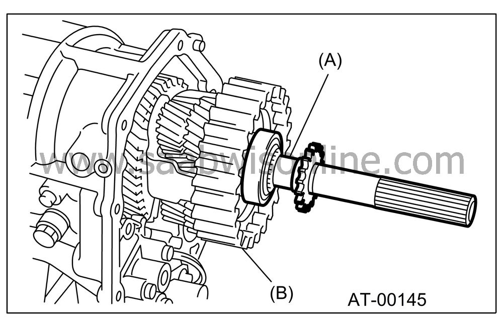
Insert the rear driveshaft into the reduction drive gear and center differential assembly.
|
(A)
|
Rear drive shaft
|
|
(B)
|
Center
differential carrier
|
Using the special tool, measure the distance “A” between the mating surface of extension case and multi-plate clutch (LSD) piston.
ST 32005073 GAUGE
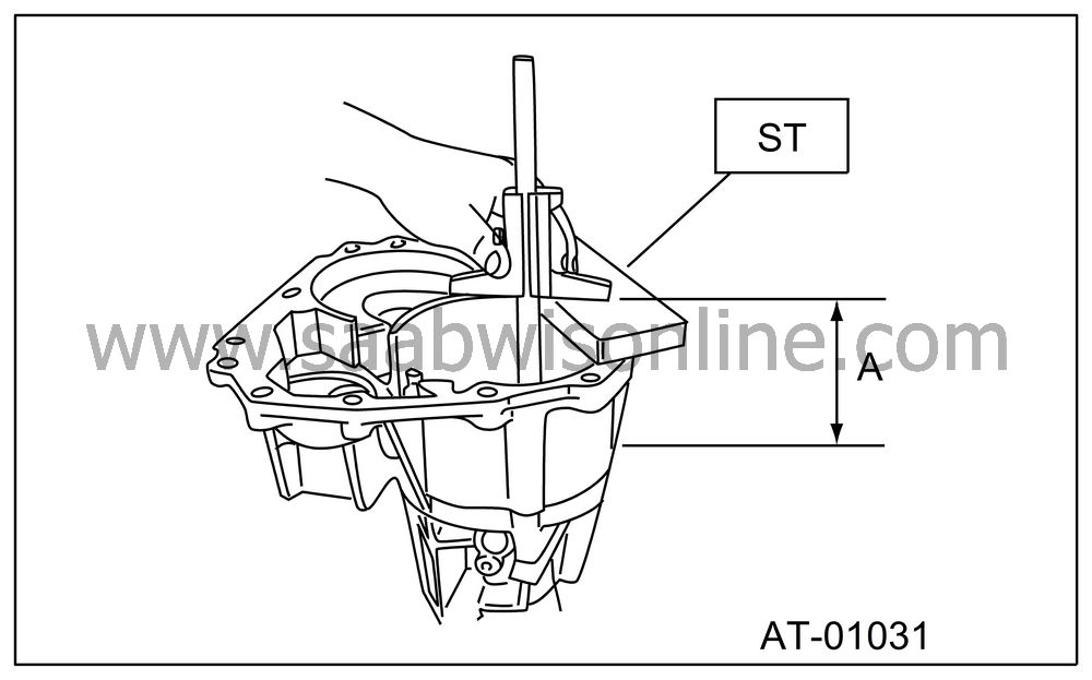
|
A:
|
Measured
value
|
Using the ST, measure the distance “B” between the mating surface of transmission case and reduction drive gear edge.
ST 32005073 GAUGE
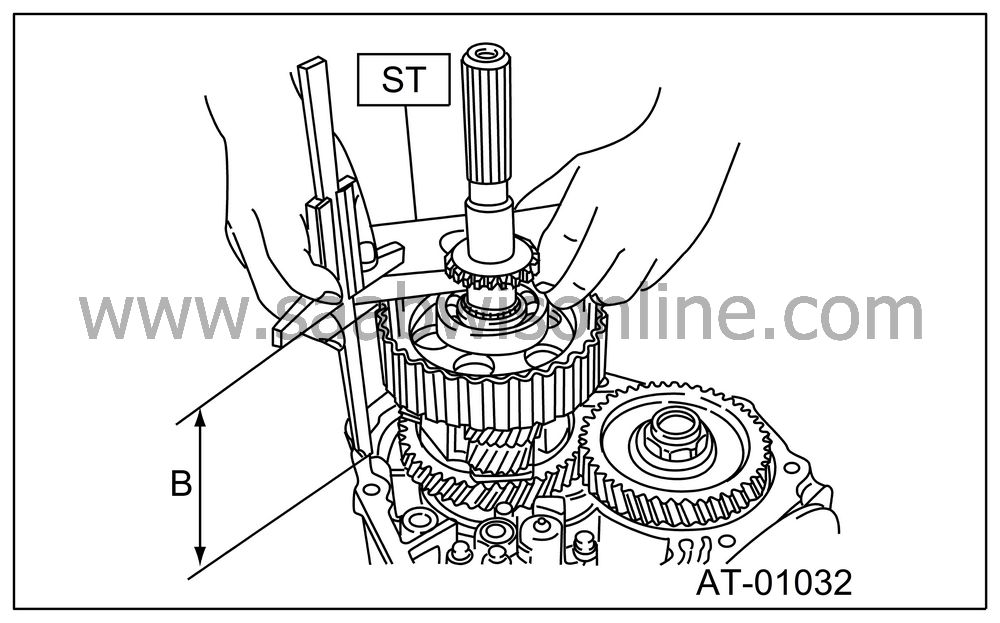
|
B:
|
Measured
value
|
Formula:
| Note | ||
| • |
Calculation of “T”:
When clearances are 0.05 mm (0.0020 in), select up to four adjusting shims from the table, suitable for clearance value. When clearances are 0.05 mm (0.0020 in) T = A − B + 0.40 mm [T = A − B + 0.0157 in] When clearances are 0.25 mm (0.0098 in) T = A − B + 0.20 mm [T = A − B + 0.0079 in] T: Shim clearance A: Distance between extension case edge and rear driveshaft edge B: Distance between transmission case edge and reduction drive gear edge T: Shim thickness 0.05 — 0.25 mm (0.0020 — 0.0098 in) Example: When, A = 90.50 mm (3.5630 in), B = 90.35 mm (3.5571 in) Calculation for 0.05 mm (0.0020 in) of clearance T = 90.50 − 90.35 + 0.4 = 0.55 [T = 3.5630 − 3.5571 + 0.0157 = 0.0216] Calculation when clearance is 0.25 mm (0.0098 in) T = 90.50 − 90.35 + 0.2 = 0.35 [T = 3.5630 − 3.5571 + 0.0079 = 0.0138] |
|
| • |
Calculation formula for “T” is applied
when measuring using ST (32005073
GAUGE). When not using ST, apply
T = (A − α + 0.45 mm) − (B − β) − H [T = (A − α + 0.0177 in) − (B − β) − H]. T: Thrust needle bearing thickness A: Distance from end of extension case to rear drive shaft ball bearing outer ring contact surface B: Distance from end of transmission case to end of rear drive shaft ball bearing α: Collar thickness used when measuring “A” β: Collar thickness used when measuring “B” 0.45: Gasket thickness (mm) H: Shim clearance After calculation, the value of “T” becomes between 0.35 mm (0.0138 in) and 0.55 mm (0.0216 in), therefore select two shims with thickness of 0.2 mm (0.010 in) or one shim with thickness of 0.5 mm (0.020 in). |
|
|
Adjusting shim
|
|
|
Part
No.
|
Thickness
mm (in)
|
|
32006797
|
0.2 (0.008)
|
|
32006798
|
0.5 (0.020)
|


