ASSEMBLY
| ASSEMBLY |
| DIFFERENTIAL CASE ASSEMBLY |
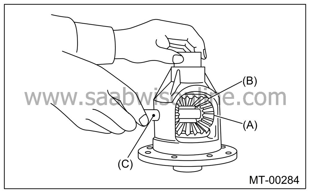
Install the bevel gear and bevel pinion together with washers, and insert pinion shaft.
| Note | ||
|
Face the chamfered side of washer toward gear. |
|
(A)
|
Bevel pinion
|
|
(B)
|
Bevel gear
|
|
(C)
|
Pinion
shaft
|
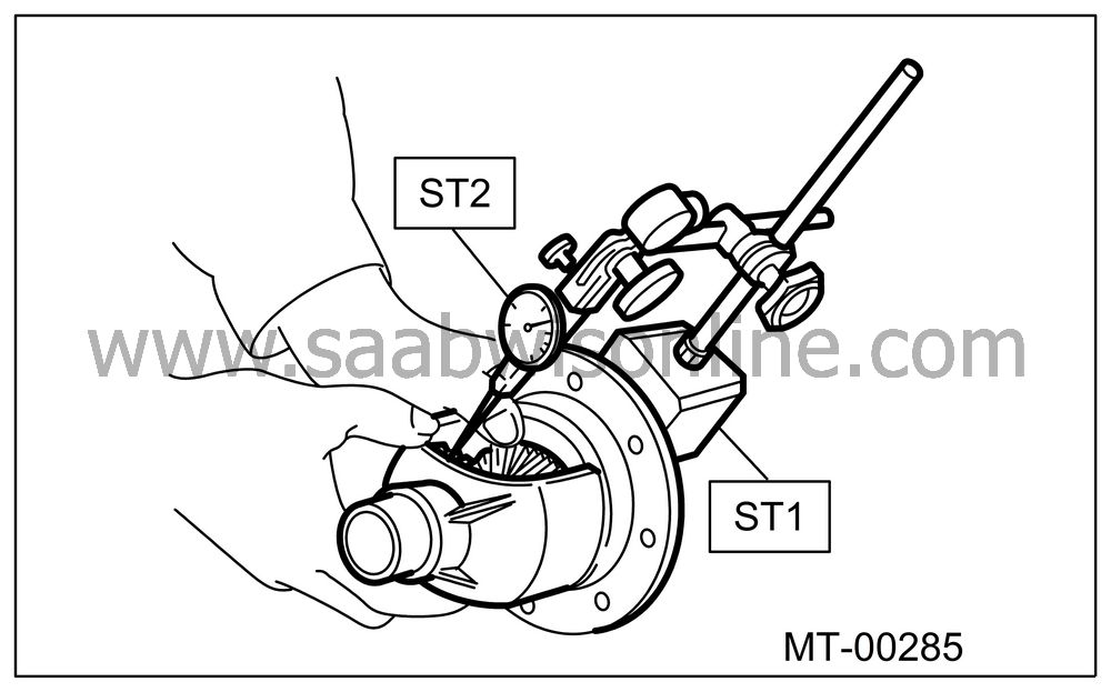
Measure the backlash between bevel gear and pinion. If it is not within specifications, install a suitable washer to adjust it.

| Note | ||
|
Be sure the pinion gear tooth contacts adjacent gear teeth during measurement. |
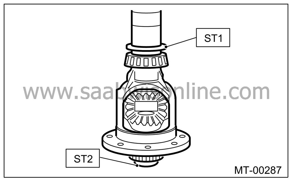
ST1 32005094 MAGNET BASE
ST2 32005095 DIAL GAUGE
Standard backlash:0.13 — 0.18 mm (0.0051 — 0.0071 in)
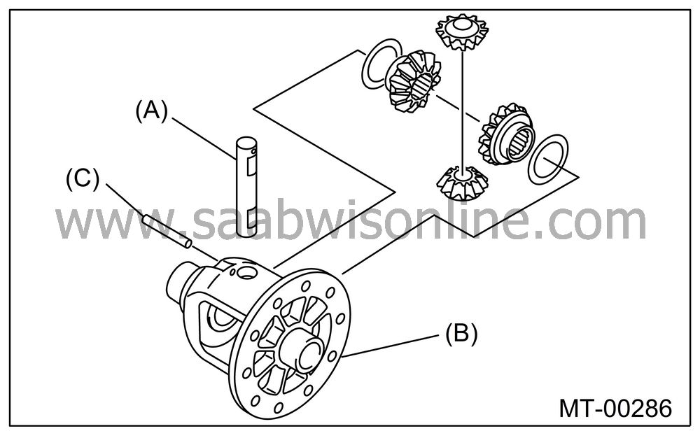
Align the pinion shaft and differential case at their holes, and drive the straight pin into holes from the hypoid driven gear side, using ST.
| Note | ||
|
Lock the straight pin after installing. |
ST 32005181 REMOVER
|
(A)
|
Pinion
shaft
|
|
(B)
|
Differential
case
|
|
(C)
|
Straight
pin
|
Install the roller bearing to differential case.
| Note | ||
| • |
Do not apply pressure in excess of 10 kN (1 ton, 1.1
US ton, 1.0 Imp ton).
|
|
| • |
Be careful because the roller bearing outer races are
used as a set.
|
|
ST1 32005130 BUSH 1-2 INSTALLER
ST2 32005065 ADAPTER
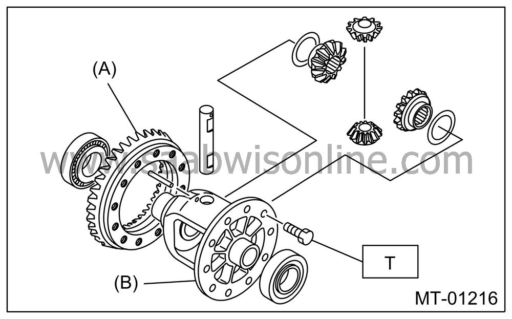
Install the hypoid driven gear to differential case using twelve bolts.
Tightening torque:
T: 62 Nm (6.3 kgf-m, 45.6 ft-lb)
|
(A)
|
Hypoid
driven gear
|
|
(B)
|
Differential
case
|
| SIDE RETAINER |
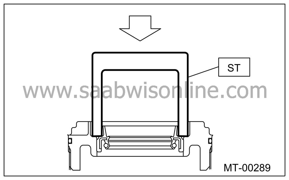
Install a new oil seal.
ST 32005024 DIFFERENTIAL SIDE OIL SEAL INSTALLER
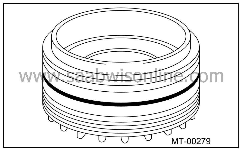
Install a new O-ring.
| Note | ||
|
Do not stretch or damage the O-ring. |
