OPERATION
| OPERATION |
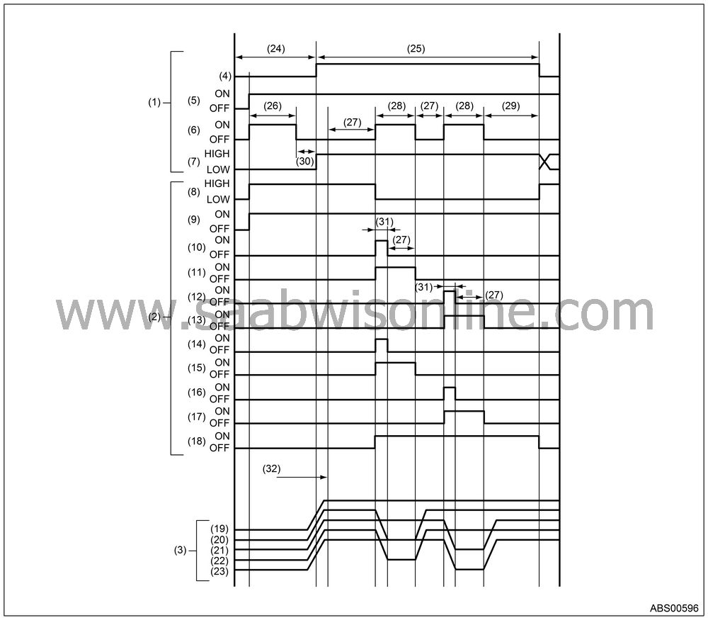
Under the ABS sequence control, after the hydraulic unit solenoid valve is driven, the operation of the hydraulic unit can be checked by means of the brake tester or pressure gauge.
ABS sequence control can be started by Vehicle Diagnostic Interface.
| ABS SEQUENCE CONTROL WITH Vehicle Diagnostic Interface |
| Note | ||
|
In the event of any trouble, the
sequence control may not be operative. In such a case, perform the diagnosis.
|
Connect the Vehicle Diagnostic Interface to data link connector under driver’s seat instrument panel lower cover.
Turn the ignition switch to ON.
Start the Vehicle Diagnostic Interface.
Put the Vehicle Diagnostic Interface to “BRAKE CONTROL” mode.
When “Function check sequence” is selected, ‘ABS sequence control’ will start.
When the message “Press Brake Pedal with braking force of 100 to 150 kgf” is displayed, perform the followings.
When using the brake tester, depress the brake pedal with braking force of 981 N (100 kgf, 221 lb).
When using the pressure gauge, depress the brake pedal so as to make the pressure gauge indicate 3,432 kPa (35 kg/cm 2 , 498 psi).
When the message “Press YES” is displayed, press the YES key.
The braking system in operation is displayed on Vehicle Diagnostic Interface.
| CONDITIONS FOR ABS SEQUENCE CONTROL |

|
(1)
|
Operational guide line of sequence control
|
(10)
|
FL outlet
valve
|
(22)
|
Pressure
of RR wheel cylinder
|
|
(11)
|
FL inlet
valve
|
(23)
|
Pressure
of RL wheel cylinder
|
||
|
(2)
|
Operational pattern of sequence control
|
(12)
|
FR outlet
valve
|
(24)
|
4 km/h
(2 MPH) or less
|
|
(13)
|
FR inlet
valve
|
(25)
|
10 km/h
(6 MPH) or less
|
||
|
(3)
|
Operational pressure of sequence control
|
(14)
|
RR outlet
valve
|
(26)
|
2.0 seconds
|
|
(15)
|
RR inlet
valve
|
(27)
|
1.0 second
|
||
|
(4)
|
Speed of
all wheels
|
(16)
|
RL outlet
valve
|
(28)
|
1.4 seconds
|
|
(5)
|
Ignition
key switch
|
(17)
|
RL inlet
valve
|
(29)
|
0.6 seconds
|
|
(6)
|
ABS warning
light
|
(18)
|
Pump motor
|
(30)
|
Within
0.5 seconds
|
|
(7)
|
Stop light
switch
|
(19)
|
Pressure
of master cylinder
|
(31)
|
0.4 seconds
|
|
(8)
|
AT ABS
signal
|
(20)
|
Pressure
of FL wheel cylinder
|
(32)
|
Point A
|
|
(9)
|
Valve relay
|
(21)
|
Pressure
of FR wheel cylinder
|
| Note | ||
| • |
When the Vehicle
Diagnostic Interface is used, control operation starts at point
A. (However, the stop light switch must be ON before point A.)
|
|
| • |
HIGH means high voltage.
|
|
| • |
LOW means low voltage.
|
|


