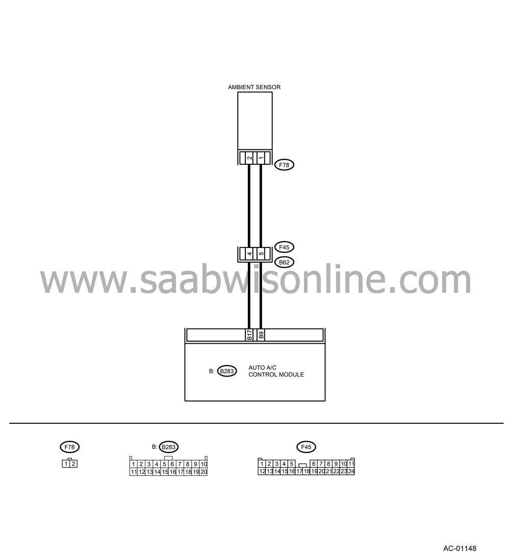
AMBIENT SENSOR
| AMBIENT SENSOR |
TROUBLE SYMPTOM:
Fan speed is not switched when the fan speed control dial is in AUTO position.
WIRING DIAGRAM:

CHECK AMBIENT SENSOR.
Turn the ignition switch to OFF.Disconnect the connector from ambient sensor.
Measure the resistance between connector terminals of ambient sensor.
Terminals
No. 1 — No. 2:
Is the resistance approx. 2.2 kΩ at 25°C (77°F)?
| Yes |
| No |
Replace the ambient sensor.
CHECK INPUT SIGNALS FOR AMBIENT SENSOR.
Turn the ignition ON.Measure the voltage between (F78) connector terminals.
Connector & terminal
(F78) No. 1 (+) — No. 2 (−):
Is the voltage approx. 5 V?
| Yes |
| No |
CHECK OUTPUT SIGNALS FROM AUTO A/C CONTROL MODULE.
Turn the ignition switch to OFF.Pull out the auto A/C control unit.
Disconnect the connector from ambient sensor.
Turn the ignition switch to ON.
Measure the voltage between connector terminals of auto A/C control module.
Connector & terminal
(B283) No. 9 (+) — No. 17 (−):
Is the voltage approx. 5 V?
| Yes |
| No |
CHECK HARNESS CONNECTOR BETWEEN AUTO A/C CONTROL MODULE AND AMBIENT SENSOR.
Turn the ignition switch to OFF.Disconnect the connectors from auto A/C control module.
Measure the resistance of harness between auto A/C control module and ambient sensor.
Connector & terminal
(F78) No. 1 — (B283) No. 9:
Is the resistance less than 1 Ω?
| Yes |
| No |
Repair the open circuit in harness between auto A/C control module and ambient sensor.
CHECK HARNESS CONNECTOR BETWEEN AUTO A/C CONTROL MODULE AND AMBIENT SENSOR.
Measure the resistance of harness between auto A/C control module and ambient sensor.Connector & terminal
(F78) No. 2 — (B283) No. 17:
Is the resistance less than 1 Ω?
| Yes |
| No |
Repair the open circuit in harness between auto A/C control module and ambient sensor.
CHECK POOR CONTACT IN AUTO A/C CONTROL MODULE CONNECTOR.
Check poor contact in auto A/C control module connector.Is there poor contact in connector?
| Yes |
Repair the connector.
| No |
Replace the auto A/C control module.


