(210-2148 ed. 3) Fault diagnosis in connection with long start time, diesel
Symptom: Difficult to start engine. Reduced driveability.
| SERVICE INFORMATION | |
| Bulletin Nbr: | 210-2148 ed. 3 |
| Date: ........... | Mars 2002 |
| Market: | NO, EU, RU, CH, HU, CR |
| Fault diagnosis in connection with long start time, diesel |
| Cars affected |
9-3 with diesel engine
| Background |
In connection with long start times and impaired drivability when the car has been parked overnight or on a hill, the fuel system should be tested for leakage.
Symptoms
Difficult to start engine. Reduced driveability.| Parts required |
47 73 354 Hose for return fuel line (by the metre)
95 44 271 T-pieces
81 24 141, 81 24 133, 2 x 2 copper washers for the fuel line connection on the pump
95 42 929 O-ring for fuel bridge
95 42 903 Injector seal
| Tools |
83 93 514 Charge pressure gauge
83 95 584 Adapter kit, leakage test, fuel lines
30 14 883 Pressure/vacuum pump
30 07 739 Hose pinch-off pliers
30 31 069 Nipple, bleeding equipment
88 19 096 Bleeding equipment
83 95 261 Fuel line tool
| Procedure |
|
|||||||
| • |
Ensure good ventilation! If there is approved ventilation for extraction of fuel fumes then this must be used.
|
|
| • |
Wear protective gloves! Prolonged exposure of the hands to fuel can cause irritation of the skin.
|
|
| • |
Have a fire extinguisher class BE at hand! Be aware of the risk for sparks, i.e. In connection with circuit breaking, short-circuiting, etc.
|
|
| • |
Absolutely No Smoking!
|
|
The following leakage tests are described:
A) The fuel bridge return lines
B) Suction line to tank
C) Return lines
A) The fuel bridge return lines
| 1. |
Remove the engine cover.
|
|
| 2. |
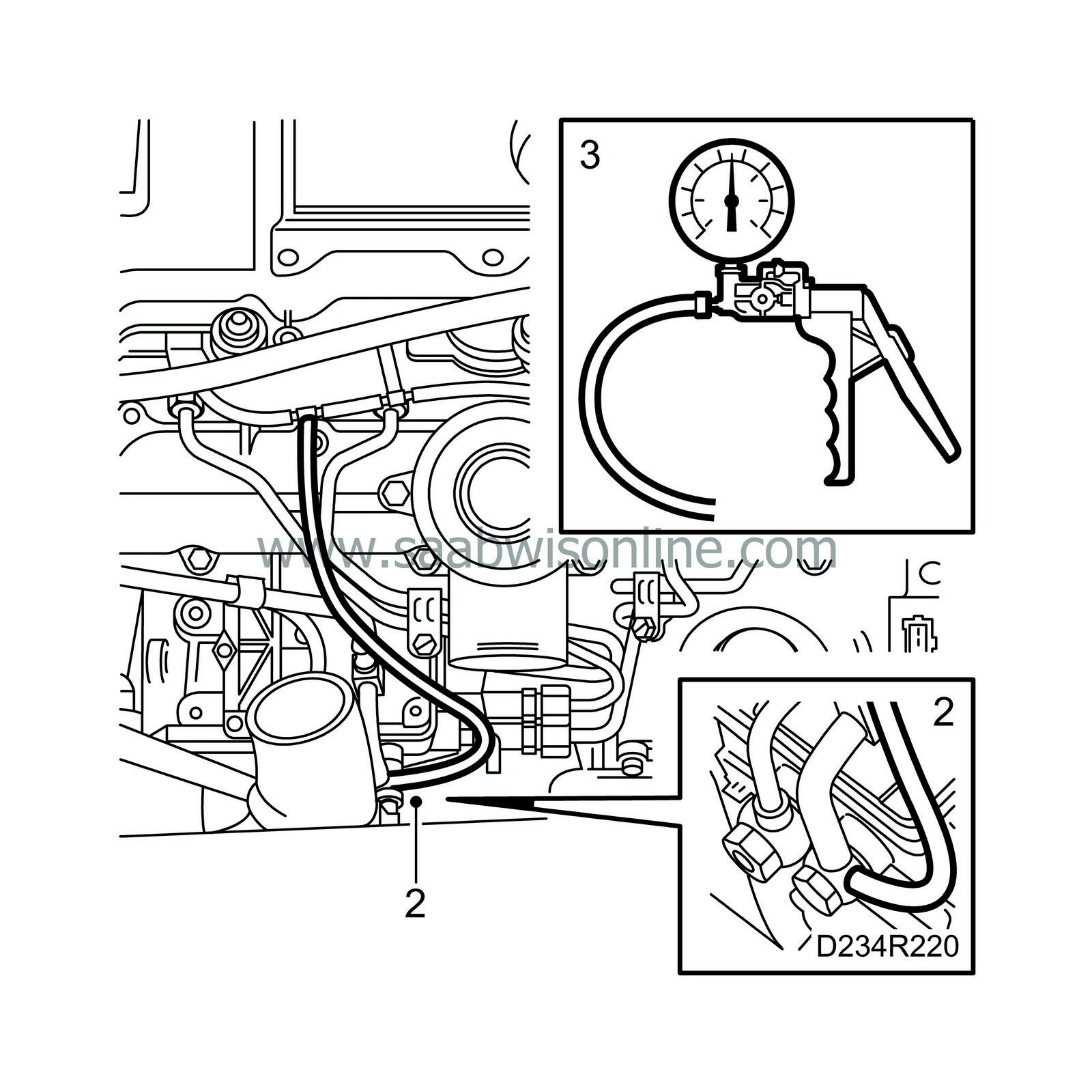
Remove the lower end (common) of the hose branch from the banjo nipple at the injection pump suction connection. Check the end of the hose for damage and cracks. Connect the hose to the
30 14 883 Pressure/vacuum pump
.
|
|
| 3. |
Create a negative pressure of -0.9 bar, wait approx. 10 minutes and check to see that the vacuum is maintained.
|
|
| 4. |
If leakage is found, each individual return hose should be checked from its respective fuel bridge as follows:
|
|
| 5. |
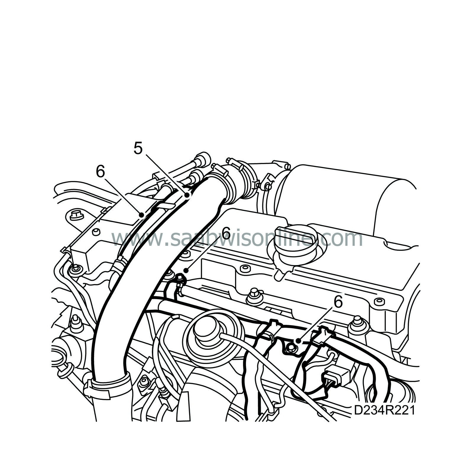
Remove the charge air pipe and plug the hoses.
|
|
| 6. |
Remove the cable duct and hose branching from the injector connection bridges.
|
|||||||||||||
| 7. |
Connect
30 14 883 Pressure/vacuum pump
in turn to the four nipples on the fuel bridges. Create a negative pressure of -0.9 bar. The pressure should remain for approx. 10 min. If the pressure changes, all four O-rings and sealing sleeves between the injector and the fuel bridge should be changed. See Basic engine, diesel, Fuel system, Fuel bridges.

|
|
| 8. |
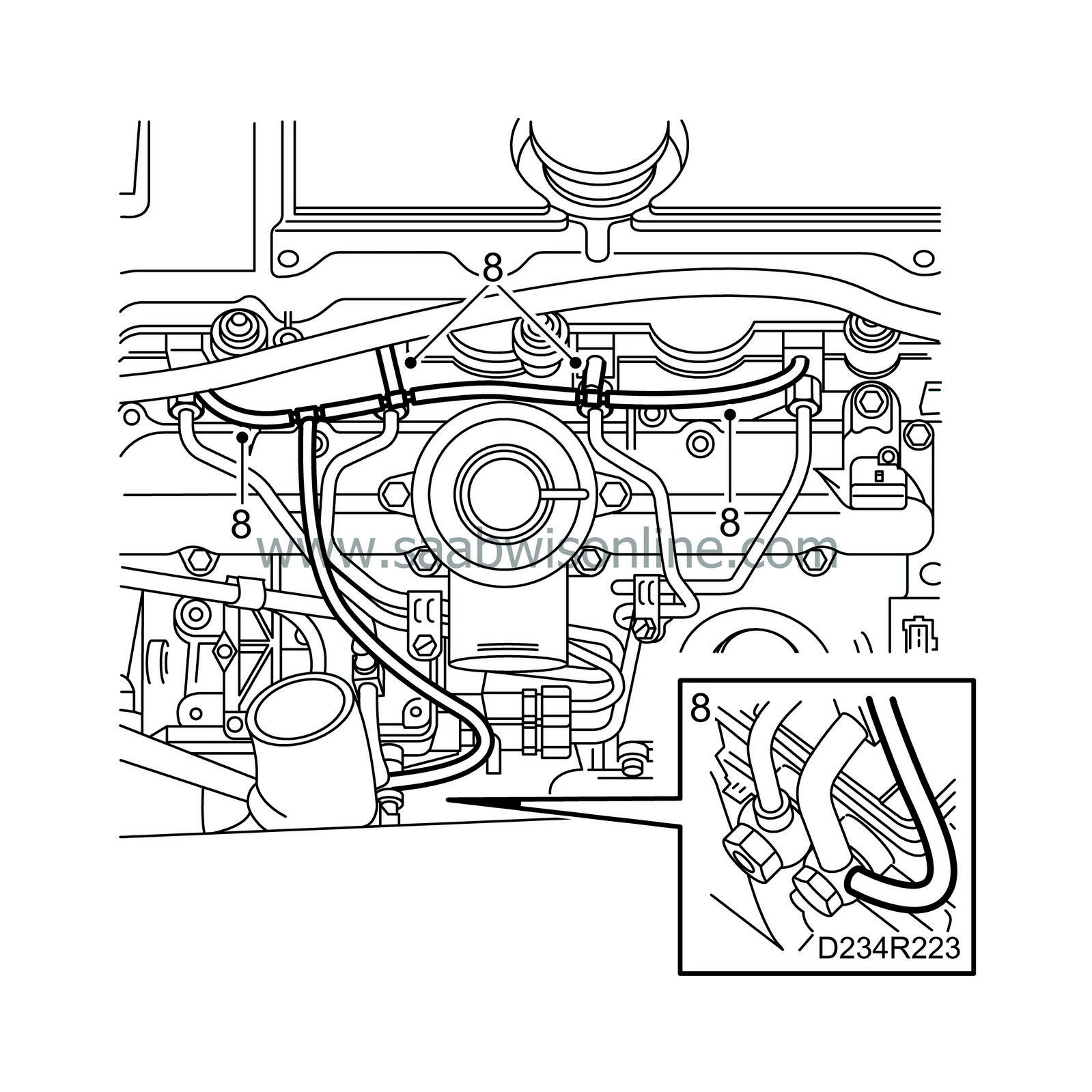
Fit the new fuel return hoses on the fuel bridges. Check the T-pieces that connect the fuel return hoses for damage, cracks, etc. Change if necessary.
|
|
| 9. |
Carry out a new leakage test by connecting the vacuum pump to the lower common hose to the inlet pipe on the fuel pump as described in point A
|
|
| 10. |
Fit the hose to the banjo nipple at the injection pump suction connection.
|
|
| 11. |
Fit the cable duct.
|
|
| 12. |
Remove the plugs and fit the charge air pipe.
|
|
B) Suction line to tank
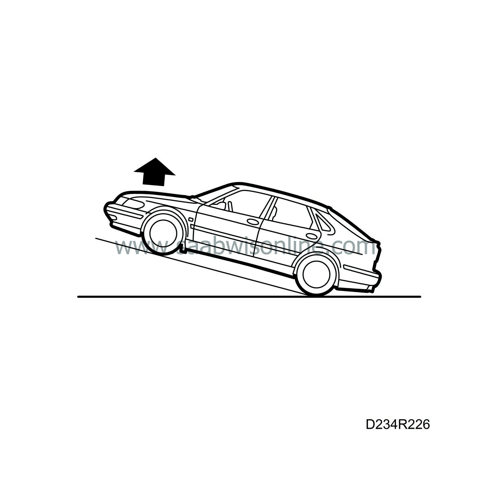
By lifting the front assembly of the car (alternatively parking on a slope) the fuel system sensitivity increases as regards to leakage. In connection with fault diagnosis we therefore recommend having the front assembly in a raised position.
Leakages in these situations are usually so small that the passage of fuel cannot be perceived. On the other hand air passage is obtained, which in this case supplies air to the fuel system.
| 1. |
Connect
83 93 514 Charge pressure gauge
and
83 95 584 Adapter kit, leakage test, fuel lines
with a hose to the service outlet on the suction line. (Suspend the pressure gauge, for example from the bonnet lock as illustrated).

|
|
| 2. |
To be able to discover leakages faster, lift the front of the car approx. 70 cm. Use axle stands.
|
|
| 3. |
Start the engine and let it run a few minutes. Stop the engine and read the pressure gauge, which due to the angle of the car and fuel quantity in the tank indicates between -0.04 - 0.08 bar. Too low a vacuum at idling speed (lower than -0.20 bar) can indicate a blocked filter or restricted suction lead. Leave the car stationary for approx. 2 hours. The pressure reading should remain the same.
|
|
| 4. |
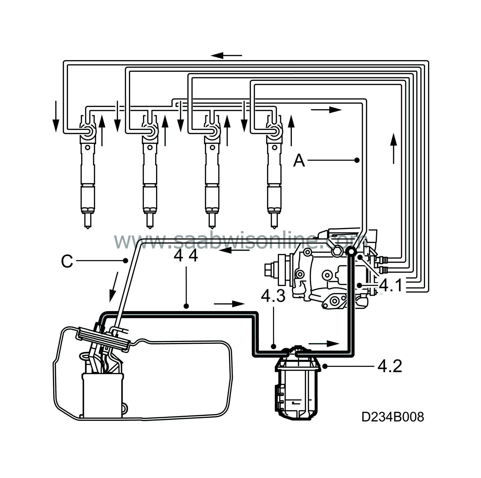
A loss of negative pressure indicates a leak in the suction line in one of the following locations: (investigate and rectify in the following order)
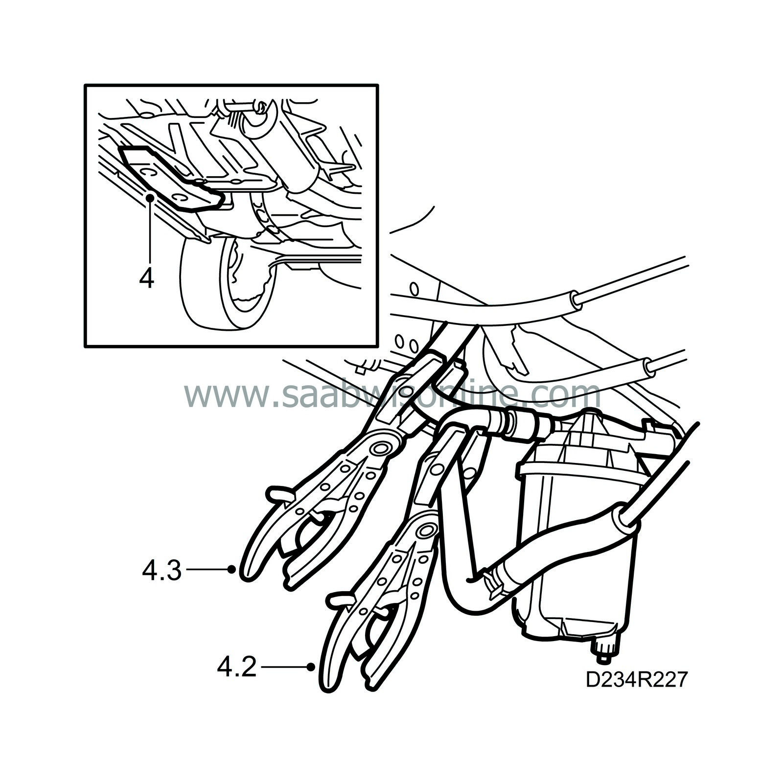
4.1) The suction line banjo connection to the injection pump. -Check the sealant surfaces against the copper gaskets (on pump, banjo nipple and hollow screw respectively). -Change copper gaskets on banjo connection. -High standards of cleanliness (dirt particles must not occur in connection with these surfaces). 4.2) Fuel filter connections, cap or housing. If the leakage still remains after pos. 4.1 has been rectified, the corresponding test with a pressure gauge can be carried out. The rubber hose in front of the fuel filter must be pinched at the same after the engine has been turned off (see pos 4.2). The hose is thereby blocked during the set up. To be able to check possible leakages in the fuel filter, repeat the test with the pressure gauge but this time move the pinch-off pliers to the feed line as illustrated. (pos 4.3) 4.3) Connection to the fuel tank and damaged fuel line from tank to filter. If there is still a leak after the tests and procedures have been carried out, the leak is between the tank connection and connection to the fuel filter. Check the connection to the tank and the feed line to the fuel filter. See To remove under Fuel tank |
|
| 5. |
On completion we recommend checking the fault diagnosis and repair as follows: Warm up the car and park it with the front raised, on a hill or on axle stands, for 12 hours. Start the engine, which should now start without any delay.
|
|
C) Return lines

| 1. |
Split the quick-release coupling on the return hose using
83 95 261 Fuel line tool
and fit
83 95 584 Adapter kit, leakage test, fuel lines
.
|
|
| 2. |
Connect
83 93 514 Charge pressure gauge
with coupling 83 95 592 to the T-nipple's service outlet. Start the engine and read the pressure gauge. The pressure must not exceed 1.0 bar. Too high a pressure indicates a blockage on the return side. Switch off the engine.

|
|
| 3. |
Check the return line for kinks. Check the ejector in the fuel level sensor for impurities. See To remove under
Fuel level sensor
.

|
|
| 4. |
Put the ignition in the OFF position, undo the pressure gauge connection, remove the T-nipple and connect the return line. Have a cloth nearby in case of fuel spillage.
|
|
Bleeding of fuel lines
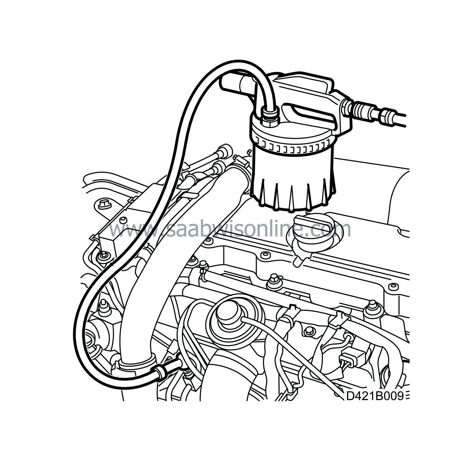
To speed up bleeding the fuel system when air gets in, for example while changing a filter or when the fuel lines on the inlet side have been removed, use the method below.
| 1. |
Connect
30 31 069 Nipple, bleeding equipment
to
88 19 096 Bleeding equipment
or equivalent and start the suction equipment.
|
|
| 2. |
Remove the end cap and connect the nipple to the service outlet on the fuel pump feed line.
|
|
| 3. |
Suck until a constant flow of fuel is seen in the suction line to the brake-bleeding tool.
|
|
| 4. |
Remove the bleed nipple from the service outlet while it is still sucking (to avoid fuel spillage and air entering the system.)
|
|
| 5. |
Put on the end cap for the service outlet.
|
|
| Warranty/Time information |
Failed object: 24151, 24224, 23443, 23457, 23447
Fault/Reason code: 61
Repair/Action code: 08
Time: Standard warranty terms apply


 Warning

