Timing cover
| Timing cover |
| 1. |
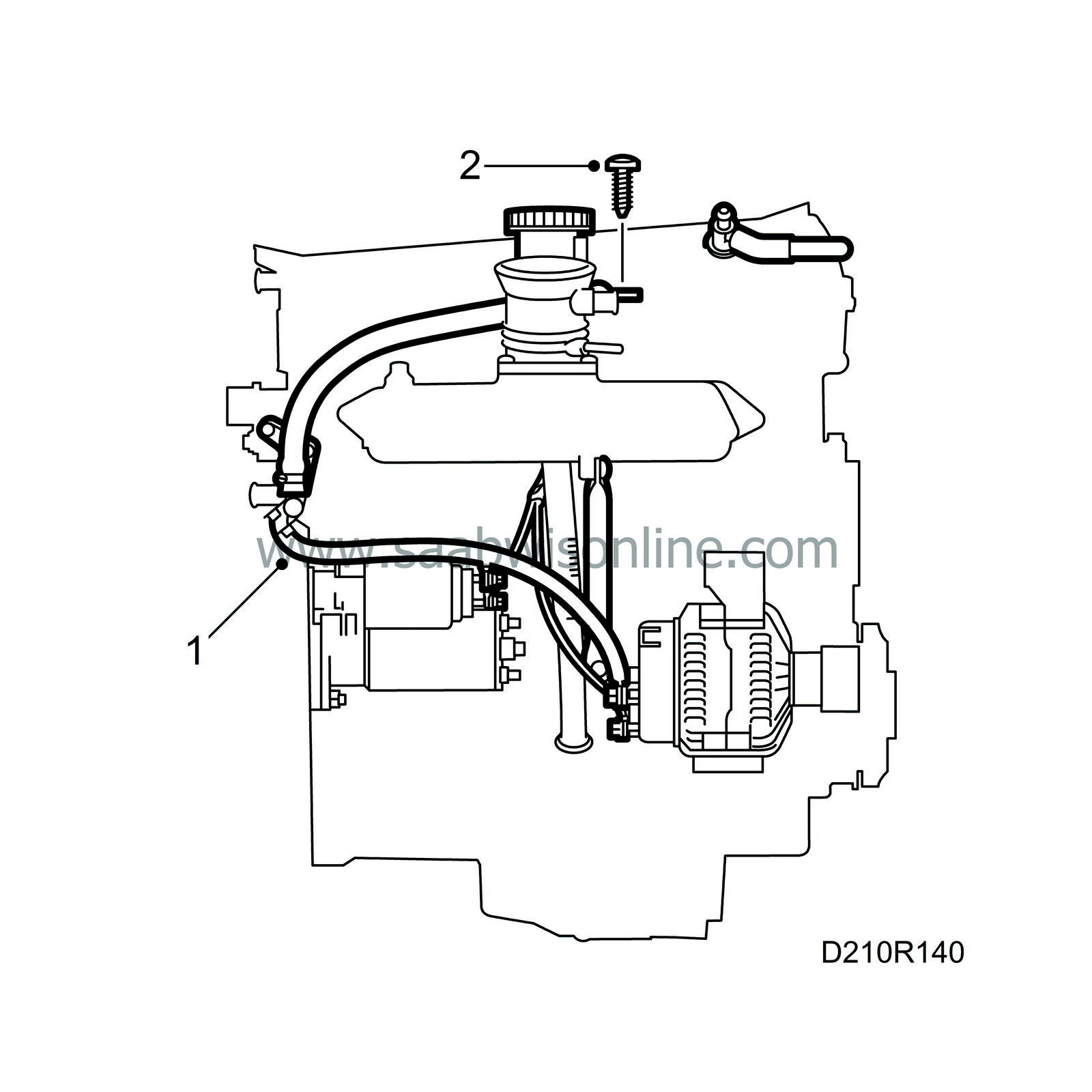
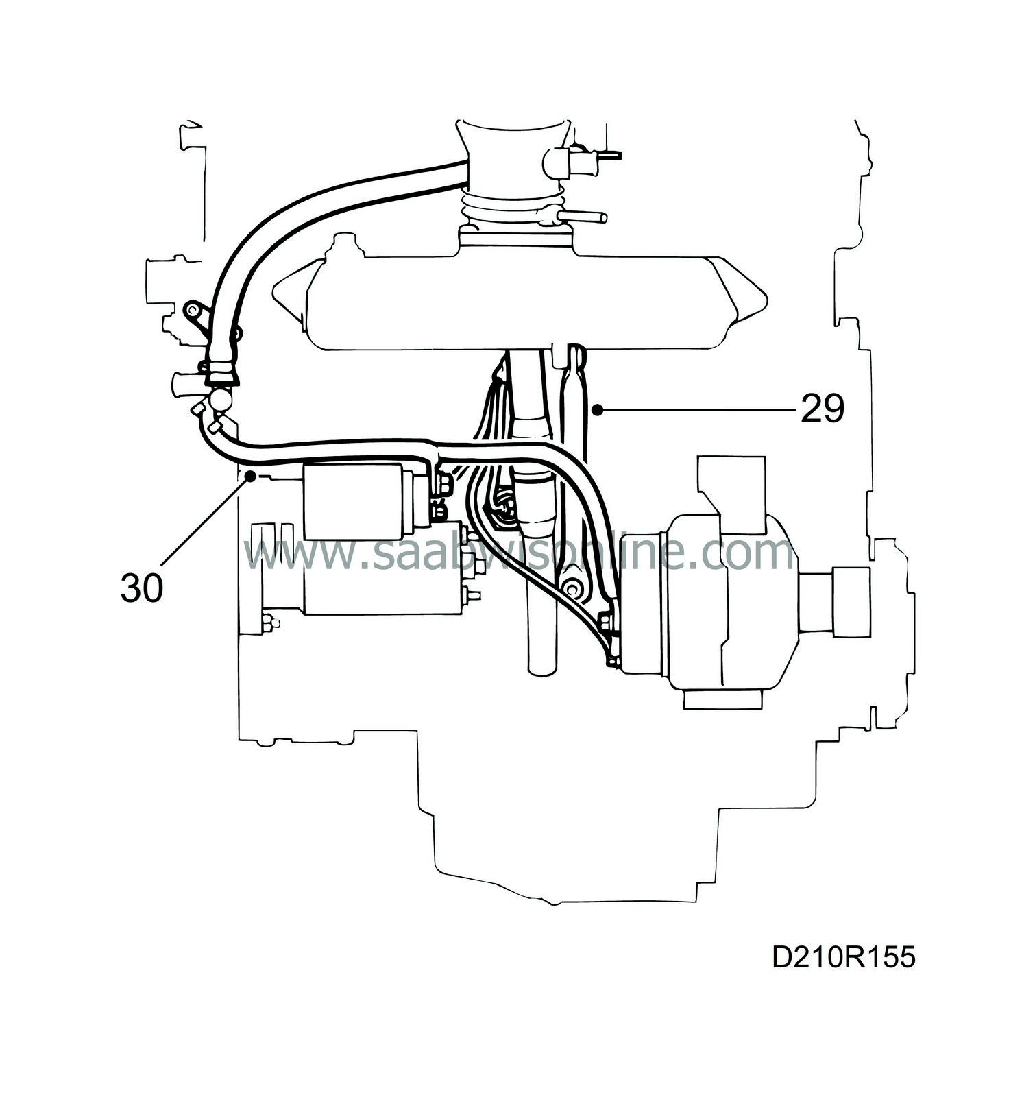
Drain the engine oil, disconnect the cables to the starter motor, generator and engine oil pressure sensor.
|
|
| 2. |
Remove the oil filler pipe and undo the intake manifold stay.
|
|
| 3. |
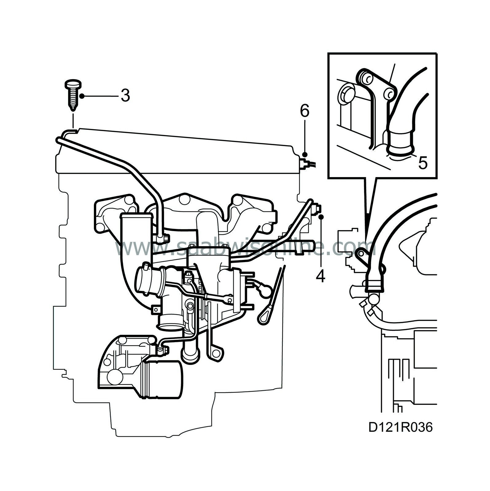
Remove the crankcase ventilation pipe with intake manifold and the nuts on the turbocharger (turbo).
|
|
| 4. |
Loosen the bolts on the turbocharger stay slightly and remove the water pipe for the turbocharger from the thermostat housing (turbo).
|
|
| 5. |
Detach the hose for the throttle body preheating and unscrew the thermostat housing cover.
|
|
| 6. |
Disconnect the ignition discharge module electrical connection (turbo) and detach the crankcase ventilation and vacuum hose from the camshaft cover.
|
|
| 7. |
Remove the cover and ignition cables (B204i/B234i) or the ignition discharge module (turbo) and place the ignition discharge module out of the way. Remove the spark plugs.
|
|
| 8. |
Remove the camshaft cover. Zero the engine and make sure the camshafts are aligned with their setting markings.
|
|
| 9. |
Remove the chain tensioner.
|
|
| 10. |
Remove the camshaft sprockets and place the chain so that the cylinder head can be removed without problem.
|
|
| 11. |
Remove the cylinder head. Start with the bolts in the timing cover and continue in reverse order to assembly. Use the protective sleeve, part no. 75 19 531, to retrieve the bolts.
|
|
| 12. |
Wipe up any oil that has run out. Make sure that the timing chain dies not obstruct removal and then lift off the cylinder head.
|
|
| 13. |
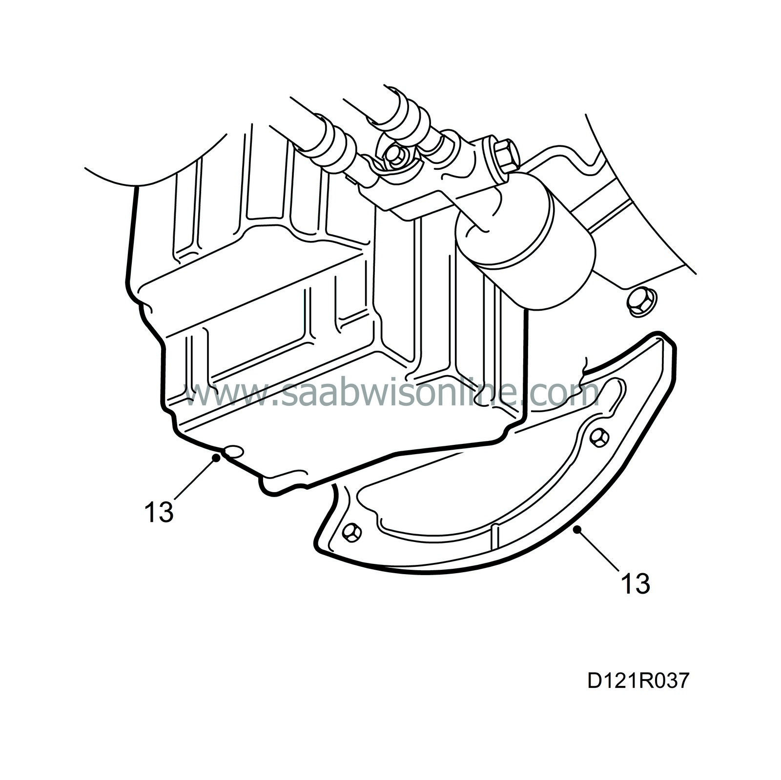
Remove the protective plate and oil sump. Leave the guide sleeve in the cylinder block. Wipe up any oil that has dripped out.
|
|
| 14. |
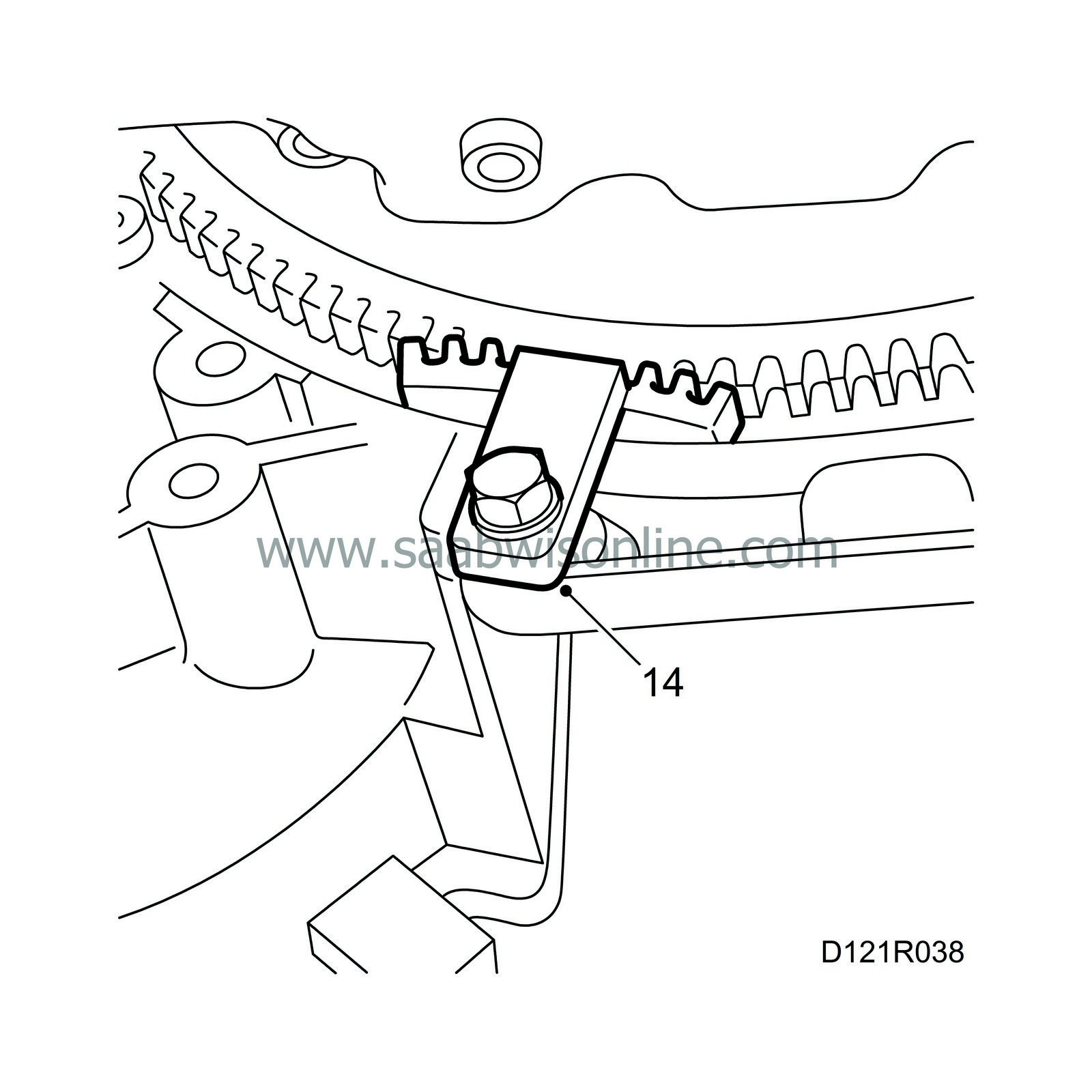
Remove the crankshaft pulley. Use the flywheel locking segment, part no. 83 94 868.
|
|
| 15. |
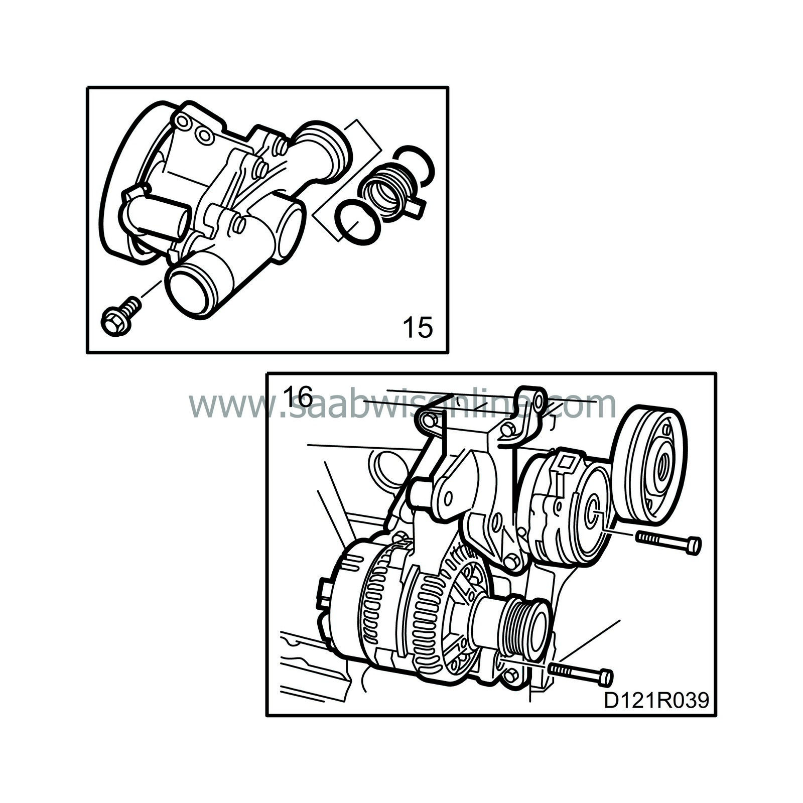
Remove the water pump and the sleeve with O-rings.
|
|
| 16. |
Remove the belt tensioner, generator and the bolt for the support bearing bracket in the timing cover.
|
|
| 17. |
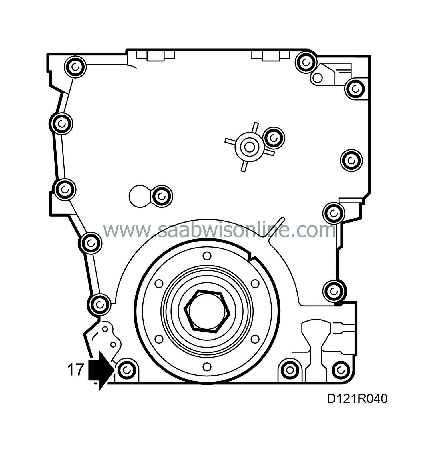
Remove all the bolts on the timing cover, carefully tap the cover off and remove it.
|
|
| To fit |
(Power train removed)
| 1. |
Thoroughly clean off any remnants of sealing compound still adhering to the surfaces concerned. Wash the areas with benzine.
|
|
| 2. |
Apply Loctite 518 in a bead approx. 1 mm wide in the centre of the sealing surfaces.
|
|
| 3. |
Fit the timing cover.
Tightening torque: 22 Nm (16.2 lbf ft). |
|
| 4. |
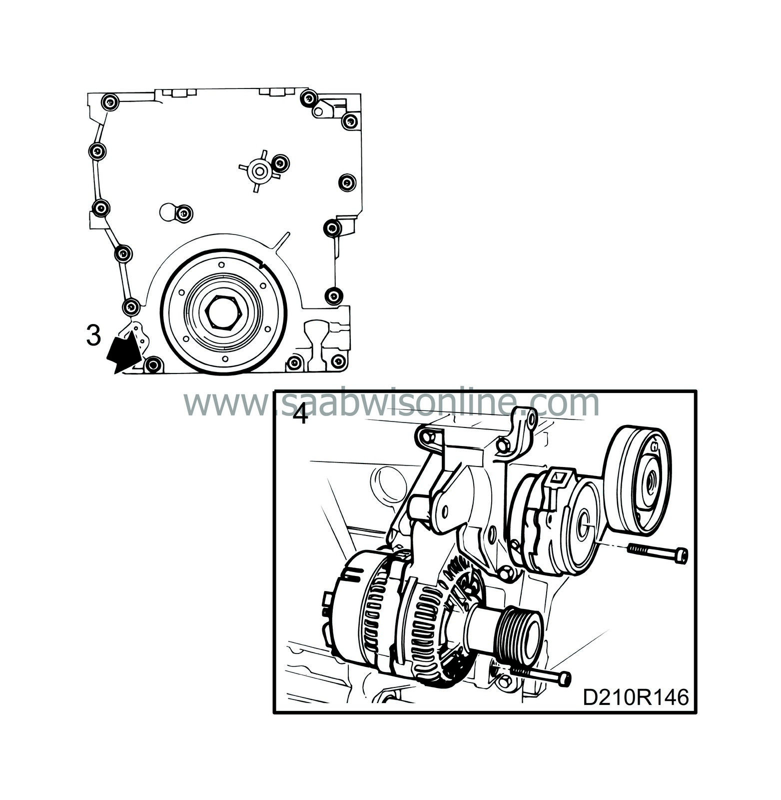
Fit the bolt for the support bearing bracket in the timing cover and fit the generator and belt tensioner.
|
|
| 5. |
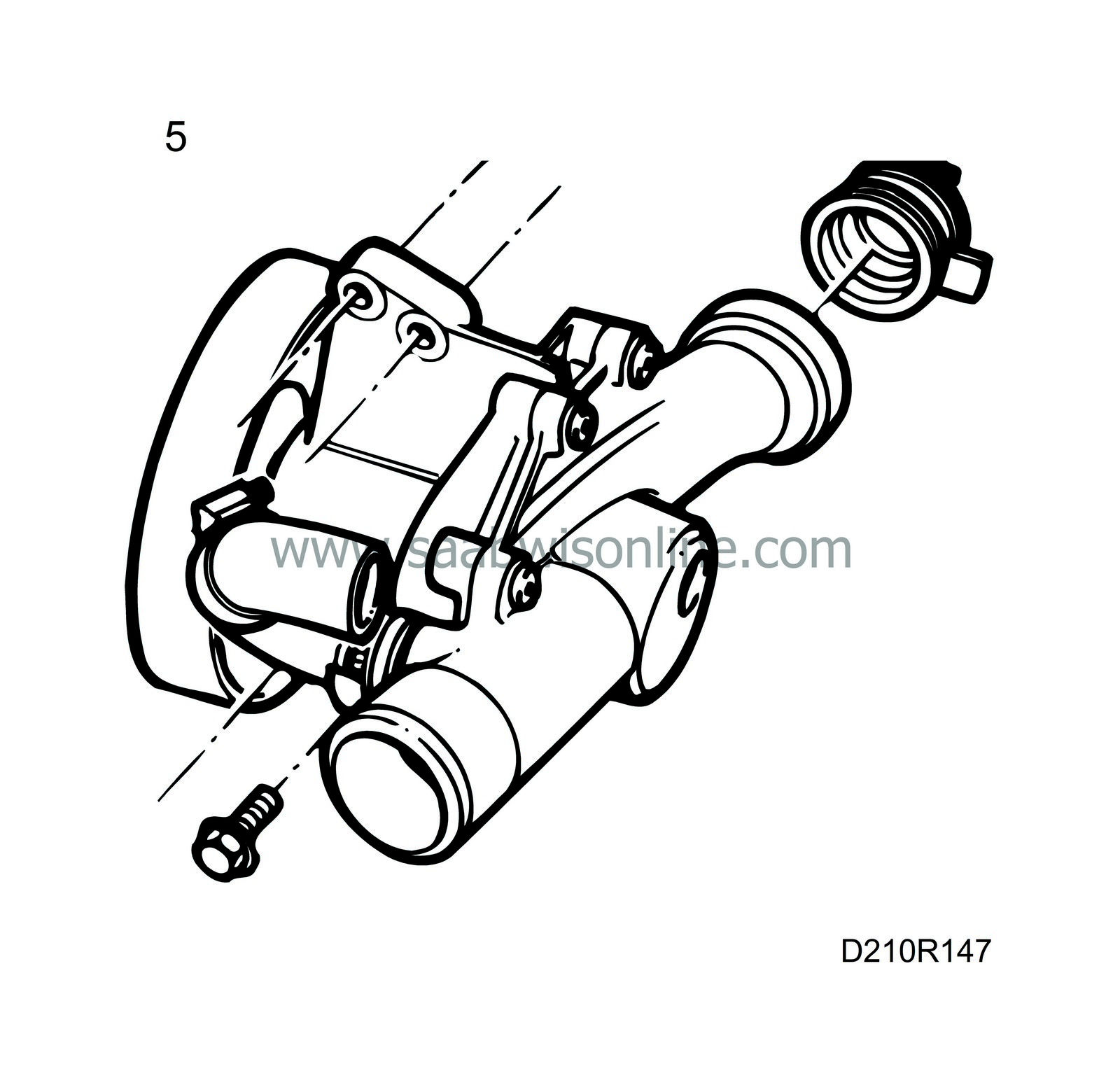
Check the condition of the water pump O-rings and replace them if necessary. Lubricate the O-rings with acid-free petroleum and fit the water pump.
|
|
| 6. |
Fit the crankshaft belt pulley. Use the flywheel locking segment, part no. 83 94 868.
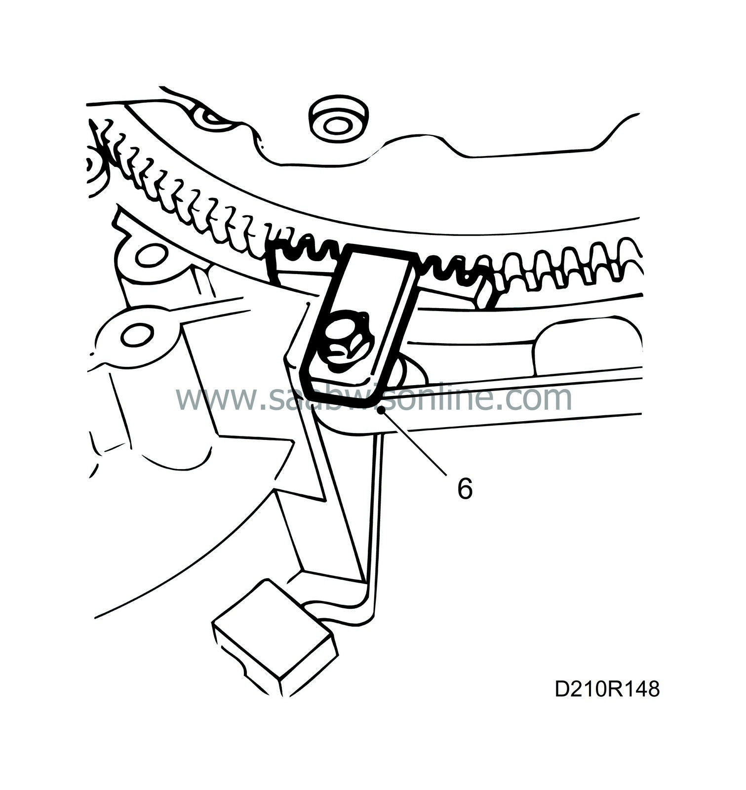
Tightening torque: 175 Nm (129.5 lbf ft). |
|
| 7. |
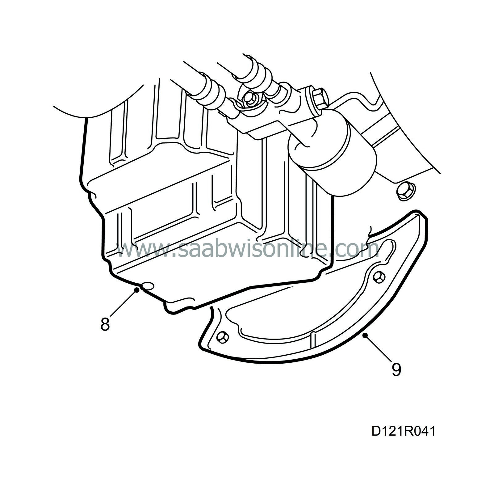
Make sure that there are no impurities or other foreign matter in the oil sump and clean its sealing surface.
|
|
| 8. |
Apply an even bead of Loctite 518 on the sealing surface of the oil sump and fit the oil sump.
Tightening torque: 22 Nm (16.2 lbf ft). |
|
| 9. |
Fit the protective plate.
|
|
| 10. |
Rotate the crankshaft 45° and fit the cylinder head with a new gasket. Make sure it is correctly seated on the guide sleeves and that the chain runs freely.
|
|
| 11. |
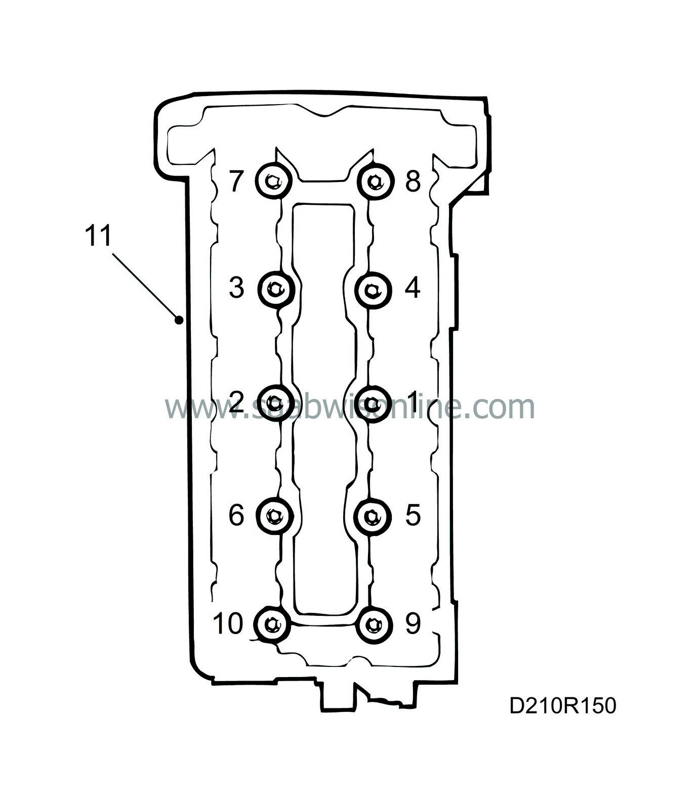
Fit and tighten the cylinder head bolts.
The tightening sequence is shown in the illustration. Tighten in three stages:Stage I: 40 Nm (29.5 lbf ft) Stage II: 60 Nm (44.3 lbf ft) Stage III: A further 90° |
|
| 12. |
Fit the two bolts between the timing cover and cylinder head.
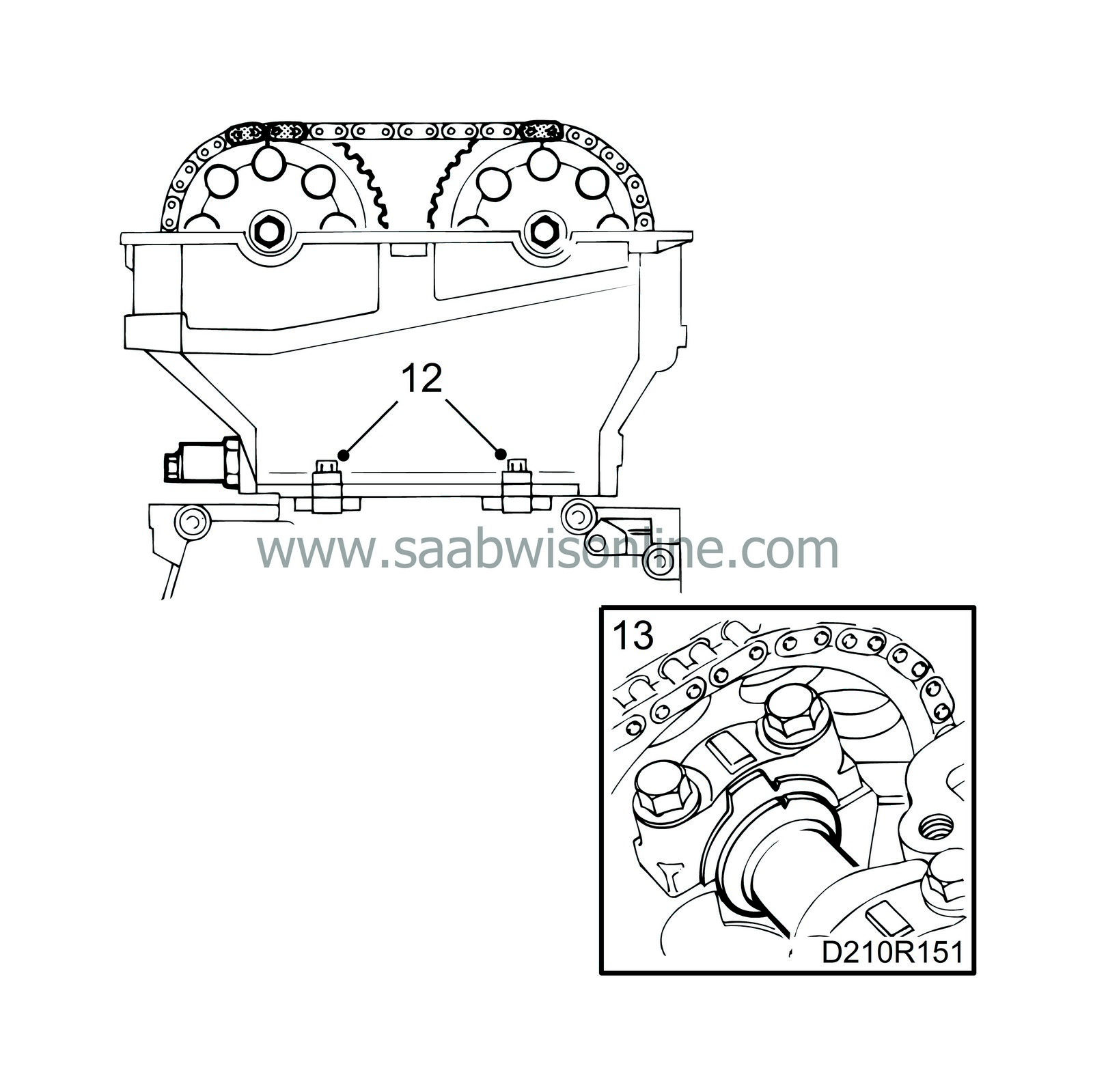
Tightening torque: 24 Nm (17.7 lbf ft) |
|
| 13. |
Make sure the camshafts are aligned with their setting markings and rotate the crankshaft back to its 0-marking.
|
|
| 14. |
Fit the camshaft sprockets and chain. Start with the intake camshaft.
|
|||||||
| 15. |
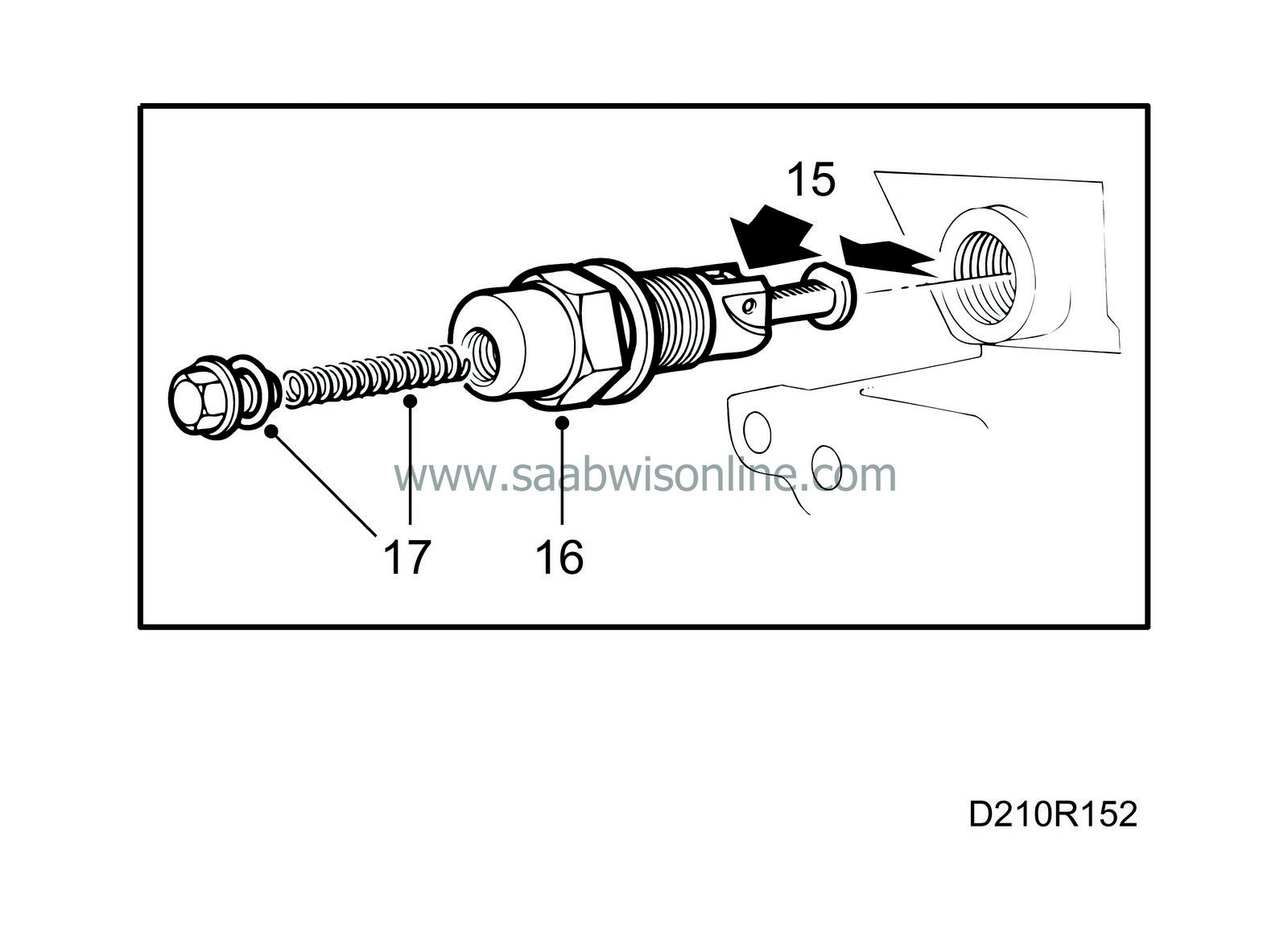
Prepare the chain tensioner for mounting by pressing down the catch and pressing in the chain tensioner.
|
|
| 16. |
Fit the chain tensioner with a 27 mm socket.
Tightening torque: 63 Nm (47 lbf ft). |
|
| 17. |
Fit the chain tensioner plug with push rod and spring.
Tightening torque: 22.5 Nm (16.6 lbf ft). |
|
| 18. |
Make sure the chain is positioned correctly on the chain guards. Rotate the crankshaft two revolutions and check the setting of the flywheel and camshafts.
|
|
| 19. |
Tighten the camshaft sprocket bolts.
Tightening torque: 63 Nm (47 lbf ft). |
|
| 20. |
Clean the sealing surface of the camshaft cover with benzine.
|
|
| 21. |
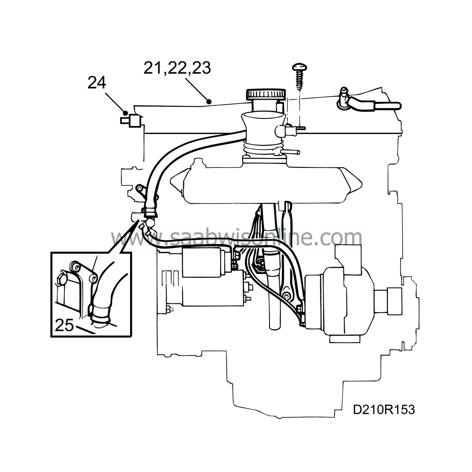
Apply soap to the opening in the camshaft cover and fit the cover, starting at the opening. Then tighten the bolt located furthest to the front at the timing chain end. Continue all the way round the outside and inside.
Tightening torque: 15 Nm (11 lbf ft) |
|
| 22. |
Fit the spark plugs.
Tightening torque: 28 Nm (20.7 lbf ft). |
|
| 23. |
Fit the ignition discharge module (turbo) or ignition leads and cover (B204i/B234i).
Tightening torques: Ignition discharge module: 11 Nm (8 lbf ft) Cover: 4 Nm (3 lbf ft) |
|
| 24. |
Connect the ignition discharge module electrical connection (turbo) and the crankcase ventilation and vacuum hoses.
|
|
| 25. |
Screw on the bolts on the thermostat housing cover and connect the hose for the throttle body preheating.
|
|
| 26. |
Fit and tighten the lock nuts on the turbocharger.
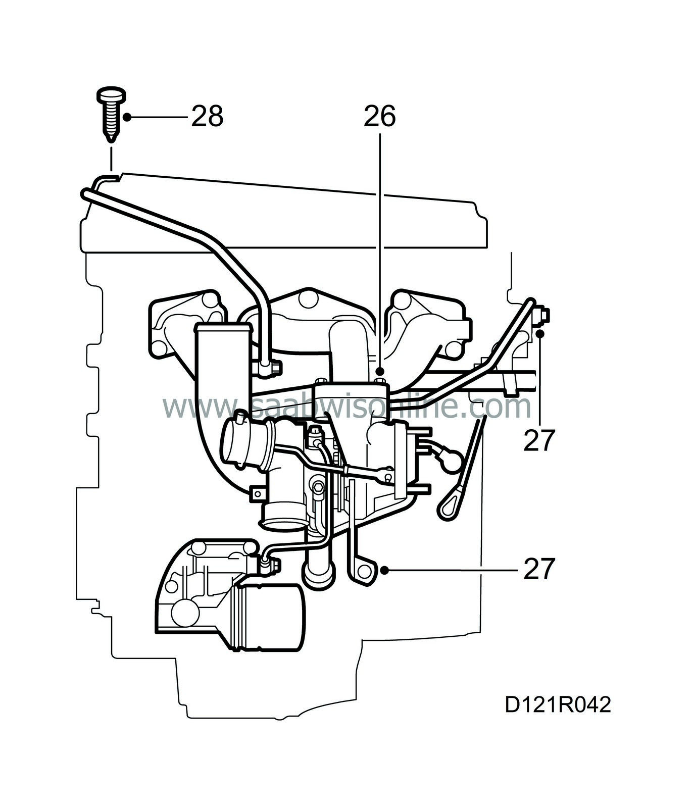
Tightening torque: 25 Nm (18.5 lbf ft) |
|
| 27. |
Tighten the bolts on the turbocharger stay. Start with the one in the cylinder block. Fit the water pipe to the thermostat housing (turbo).
Tightening torques: Turbo, stay to block: 22 Nm (16.2 lbf ft) Water pipe: 25 Nm (18.5 lbf ft) |
|
| 28. |
Fit the crankcase ventilation pipe together with the intake manifold (turbo).
Tightening torques: Turbo/intake manifold: 8 Nm (5.9 lbf ft) Crankcase ventilation pipe: 24 Nm (17.7 lbf ft) Pipe clamp: 9,5 Nm (7 lbf ft) |
|
| 30. |
Make sure the oil plug is tight and connect the cables to the engine oil pressure sensor, generator and starter motor.
|
|

