Valve stem seals
| Valve stem seals |
| To remove (in fixture) |
(Cylinder head, camshafts and valve gear removed)
| 1. |
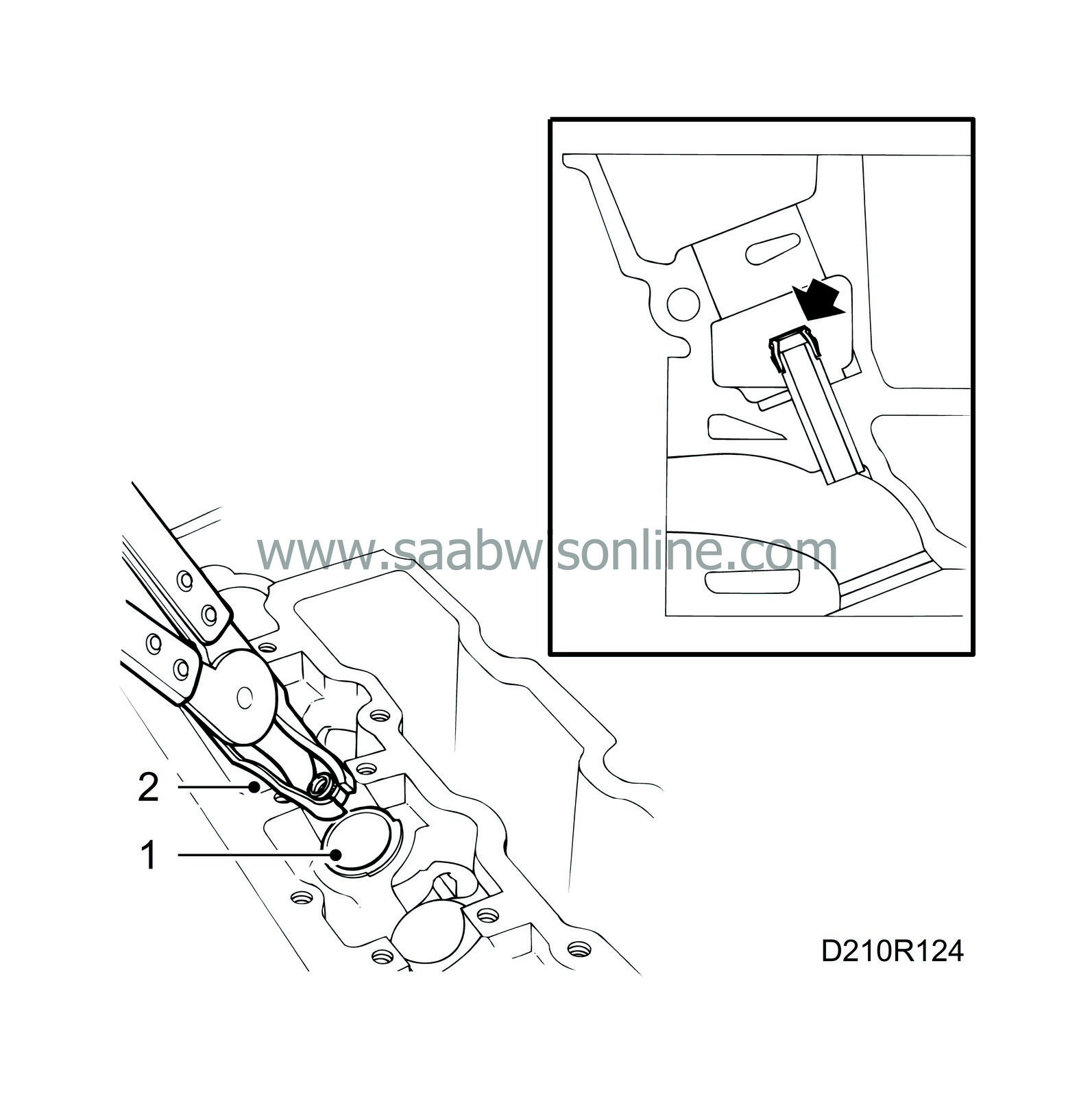
Fit protective collar, part no. 83 93 746, to protect the tappet cylinders.
|
|
| 2. |
Remove the seals from the valve guides with the pliers, part no. 83 94 157. If the guides are to be changed, remove them together with the seals.
|
|
| To fit (in fixture) |
(Cylinder head, camshafts and valve gear removed)
| 1. |
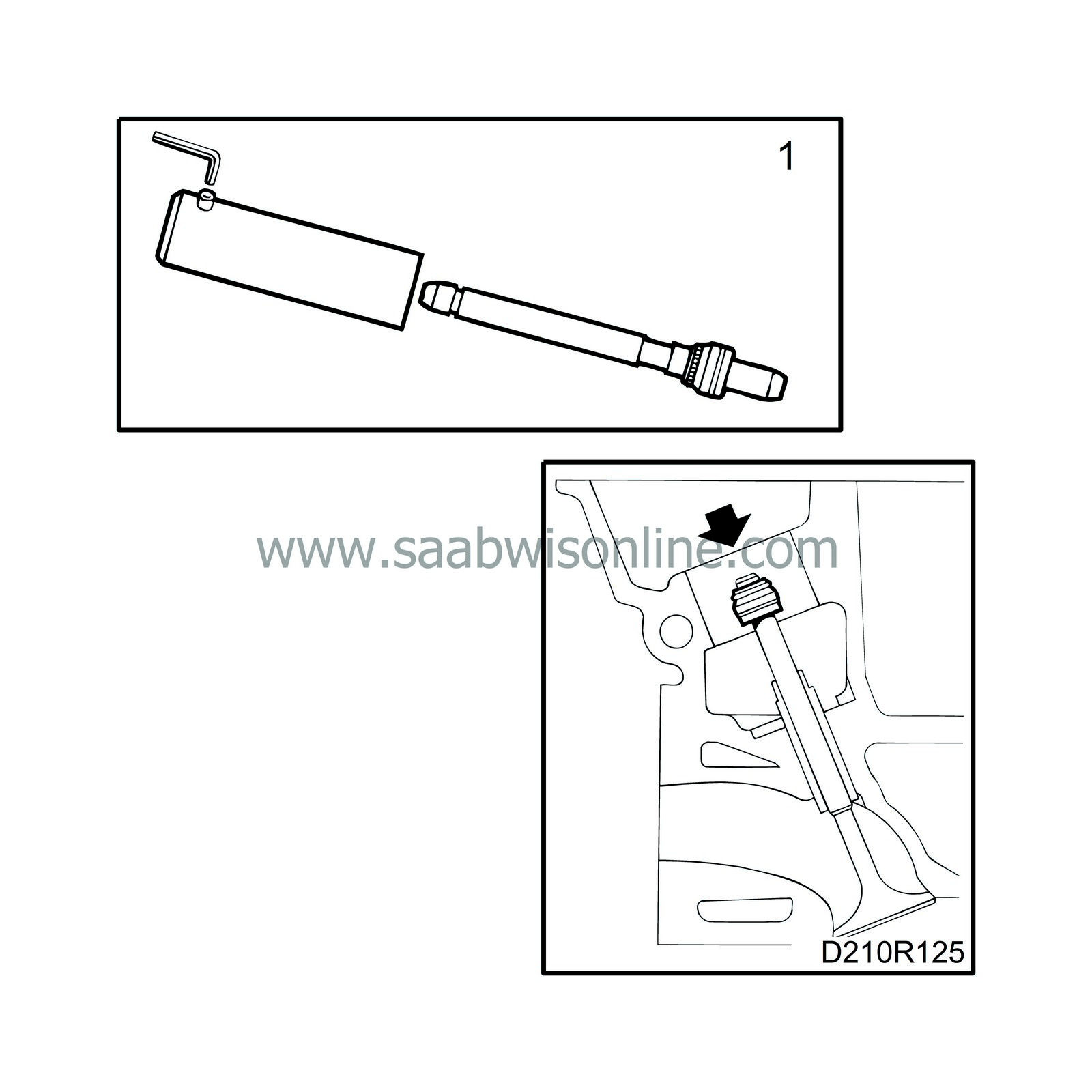
Fit the seals with the fitting tool, part no. 83 95 071. Place the seal in the tool and guide the tool into the valve guide. If the valve is fitted, use the valve stem as a guide.
|
|
| 2. |
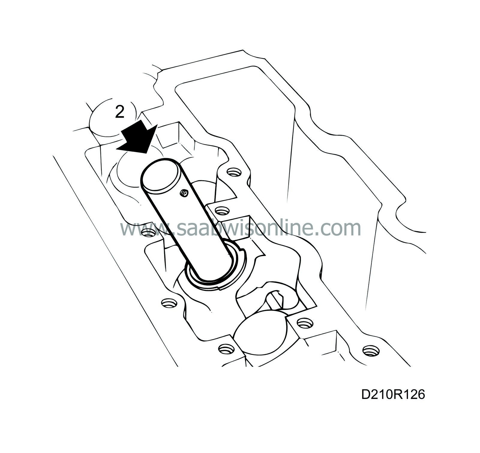
Tap the seal in place with a plastic mallet.
|
|
| To remove (in car) |
| Important | ||
|
Place all removed valve parts in the valve stand, part no. 83 93 787. |
||
| 1. |
Unplug the ignition discharge module (turbo) and remove the ignition discharge module (turbo), or alternatively the cover and the ignition leads. Undo the screw for the crankcase ventilation pipe on the camshaft cover (turbo) and remove the positive crankcase ventilation nipple and vacuum from the camshaft cover. Remove the camshaft cover.
|
|
| 2. |
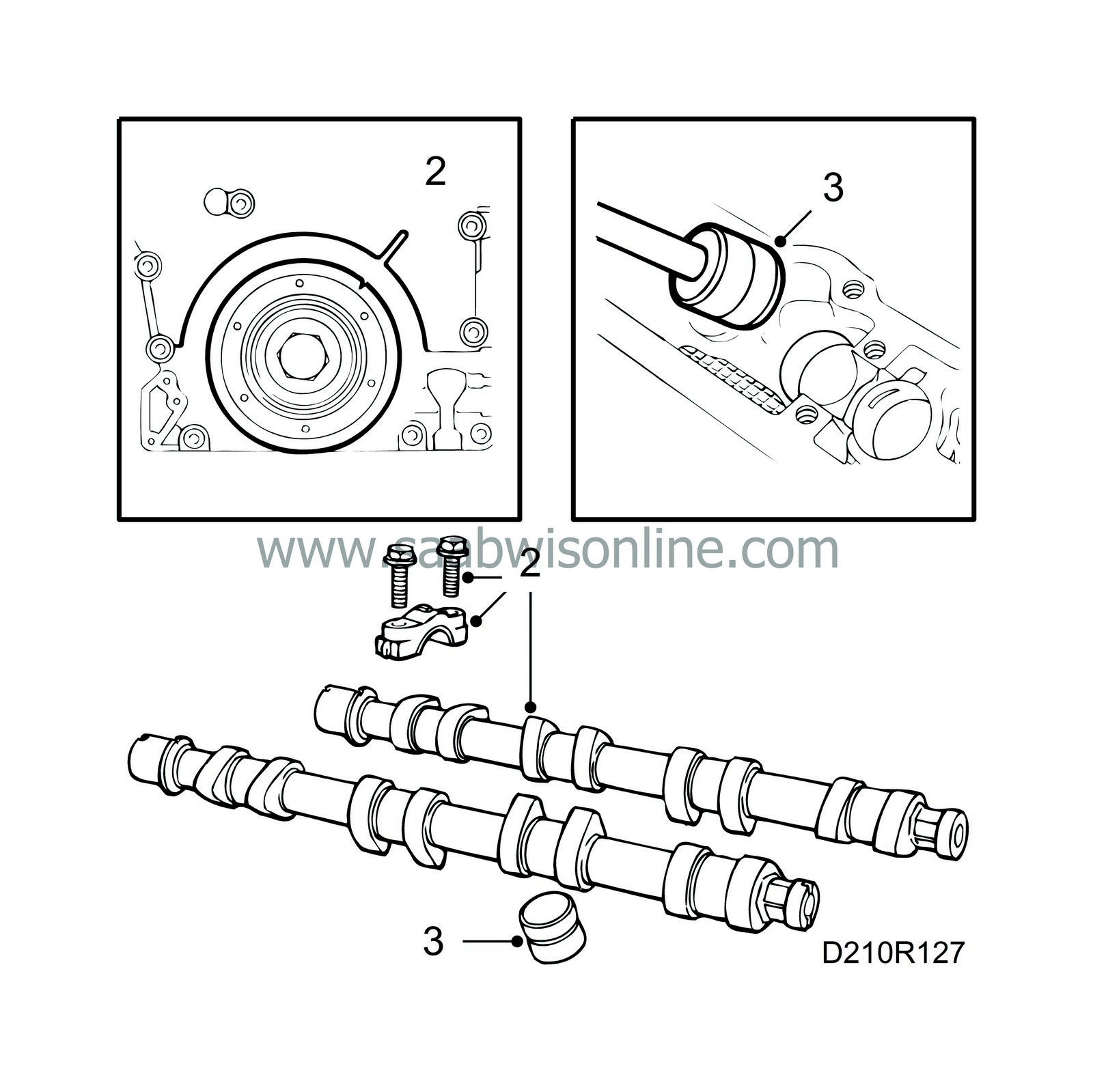
Rotate the crankshaft to the 0 mark, remove the chain tensioner and dismantle the camshafts. Cover the space for the sprockets and timing chain to prevent collets and seals from dropping down inside.
|
|
| 3. |
Lift out the tappets with the tool, part no. 83 91 401.
|
|
| 4. |
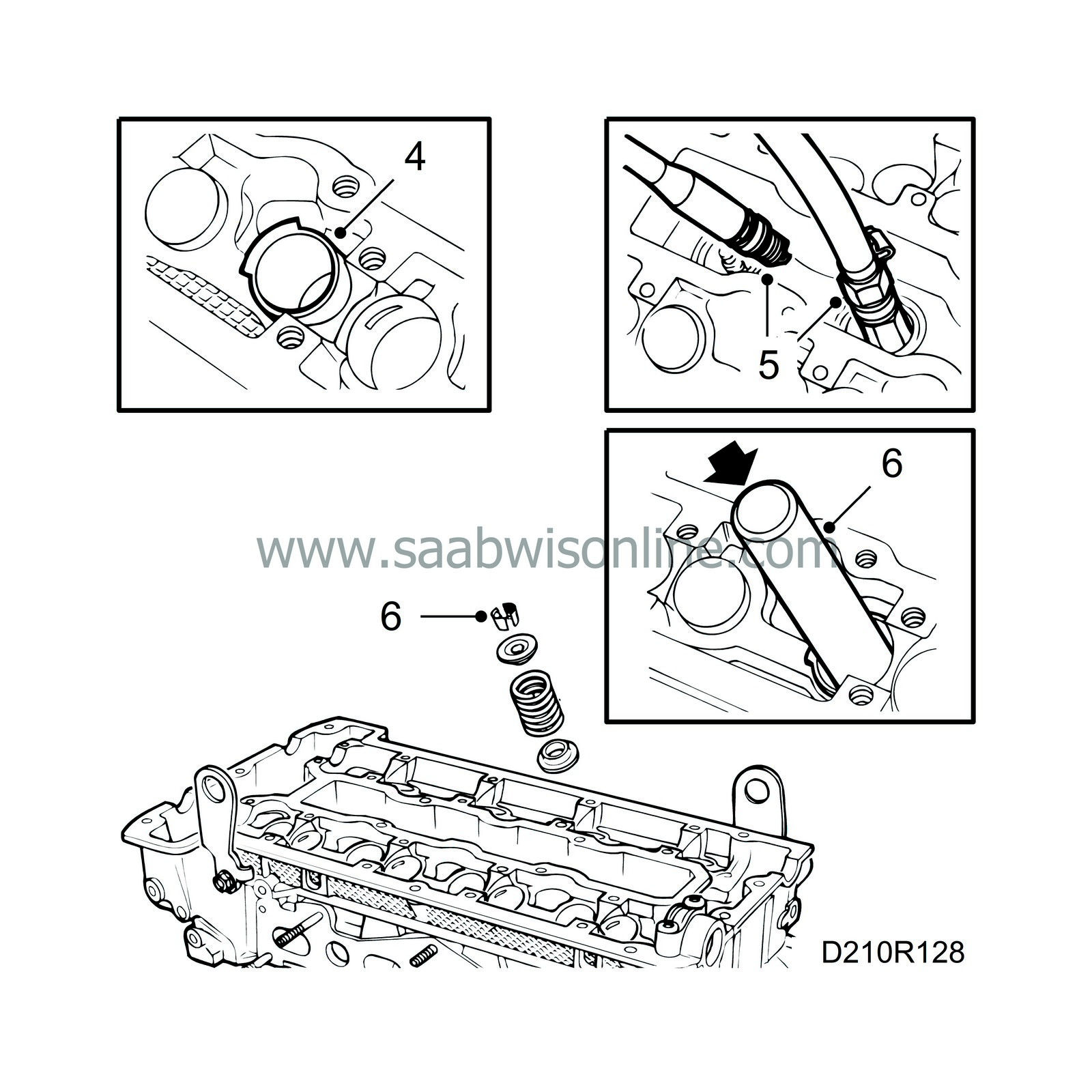
Fit the protective collars, part no. 83 93 746, around the valve springs to protect the sealing surfaces on the tappets. Observe the position of the collars.
|
|
| 5. |
Rotate the crankshaft until the piston in the cylinder concerned is at top dead centre. Lock the engine using the flywheel locking attachment, part no. 83 94 868, unscrew the spark plug in the cylinder concerned and fit the air nipple, part no. 83 94 173. Connect compressed air and pressurize the piston and valves.
|
|
| 6. |
Hold the tool, part no. 83 94 181, against the valve disc and in line with the valve stem. Give the tool a powerful blow with a hammer. The collets should then come loose from the valve and follow up with the tool.
|
|
| 7. |
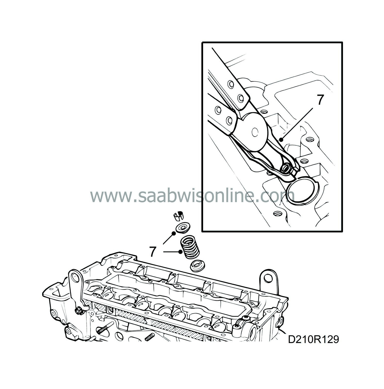
Lift out the spring disc and valve spring and remove the valve guide seal with the pliers, part no. 83 94 157.
|
|
| To fit (in car) |
| 1. |
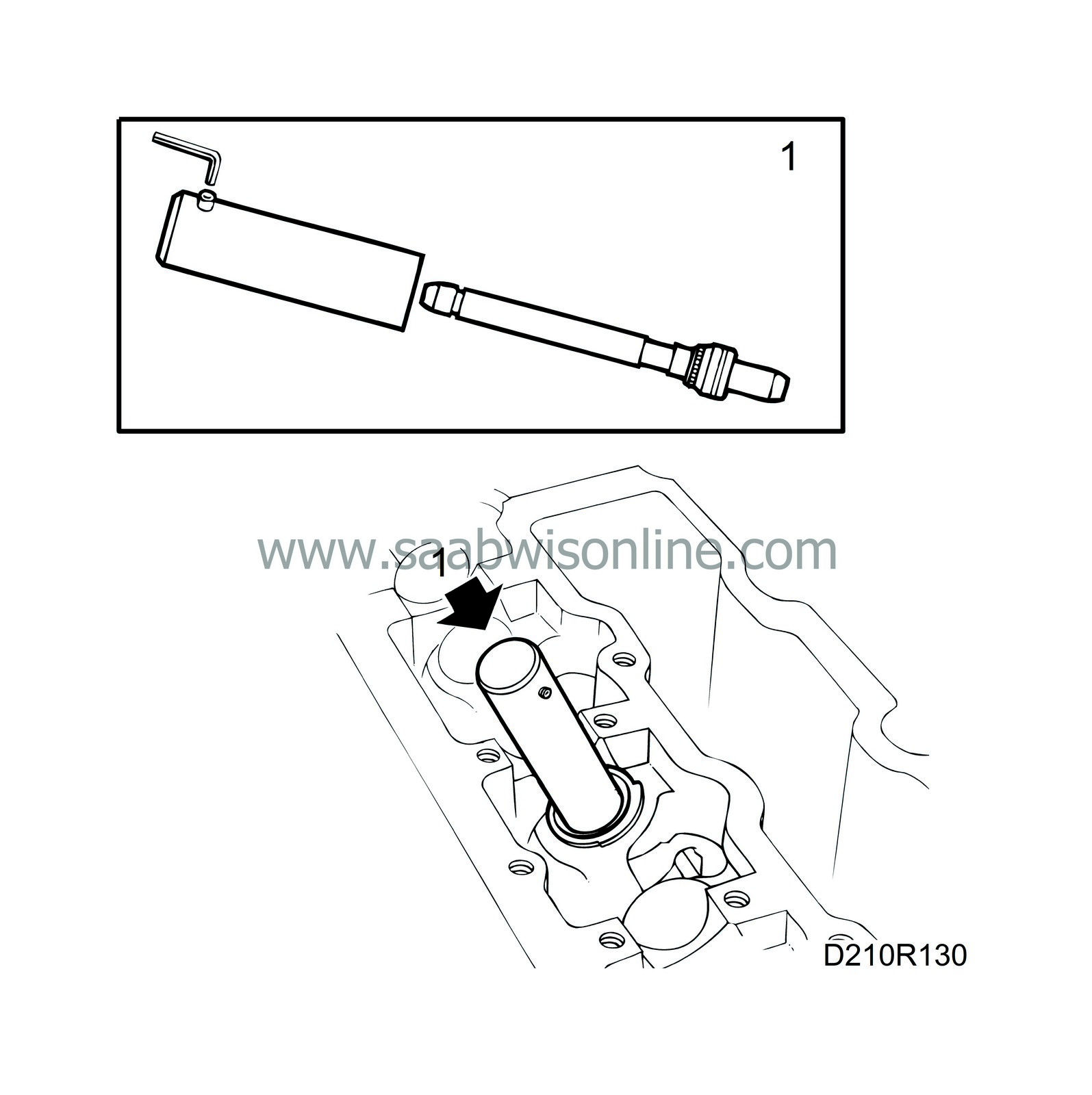
Remove the stem from
83 95 071 Fitting tool, valve stem seal
and place the valve guide seal in the tool with the rubber flange facing inward (upward on the valve stem). Fit the seal to the valve. Using a plastic mallet, gently tap the seal into position.
|
|
| 2. |
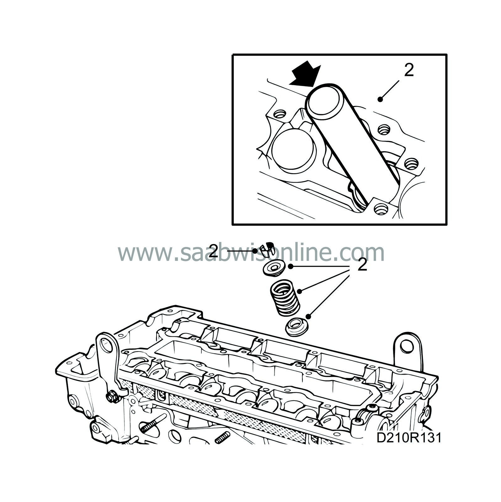
Fit the spring and spring discs, and place the valve cones in the groove on the spring discs. Using a hammer,
83 94 181 Removal tool
and
83 94 207 Fitting tool
tap the valve cones back into position.
|
|
| 3. |
Disconnect the compressed air, remove the air nipple and the flywheel locking attachment.
|
|
| 4. |
Turn the crankshaft to the 0 marking and then 45°.
|
|
| 5. |
Fit the spark plugs.
Tightening torque: 28 Nm (20.7 lbf ft) |
|
| 6. |
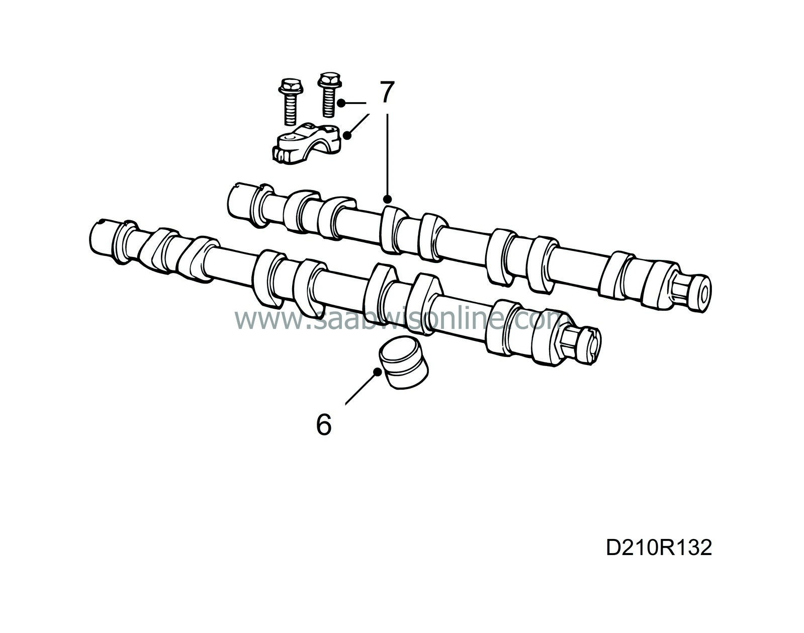
Remove the protective sleeves and fit the valve tappets.
|
|
| 7. |
Fit the camshafts and bearing caps, start where cams are pointing down and acting on the tappets. The bearing caps are marked 1-5 for the intake side and 6-10 for the exhaust side.
Tightening torque: 15 Nm (11 lbf ft)
|
||||||||||
| 8. |
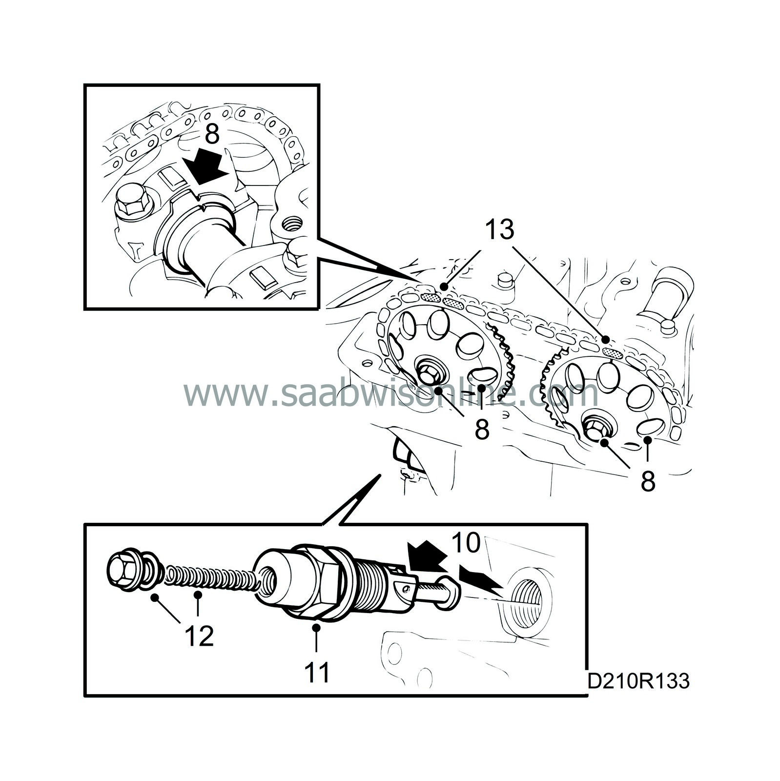
Line up the marks on the camshafts with their timing marks and fit the camshaft sprockets and timing chain. Start with the intake camshaft.
|
|||||||
| 9. |
Rotate the crankshaft back to its 0-marking.
|
|
| 10. |
Prepare the chain tensioner for mounting by pressing down the catch and pressing in the chain tensioner.
|
|
| 11. |
Fit the chain tensioner with a 27 mm socket.
Tightening torque: 63 Nm (47 lbf ft) |
|
| 12. |
Fit the chain tensioner plug with push rod and spring.
Tightening torque: 22.5 Nm (16.6 lbf ft) |
|
| 13. |
Check that the chain runs correctly on the chain guides. Rotate the crankshaft two turns and check the settings of the flywheel and camshafts. Tighten the camshaft sprocket bolts.
Tightening torque: 63 Nm (47 lbf ft) |
|
| 14. |
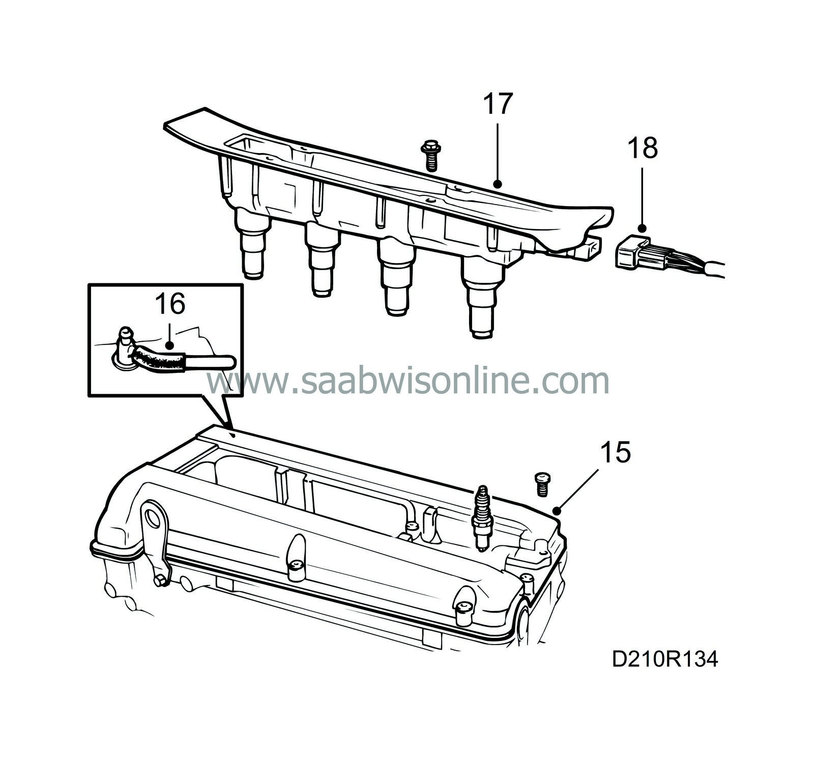
Clean the sealing surface of the camshaft cover with benzine.
|
|
| 15. |
Apply soap to the opening in the camshaft cover and fit the cover, starting at the opening. Then tighten the bolt located furthest to the front at the timing chain end. Continue all the way round the outside and inside.
Tightening torque: 15 Nm (11 lbf ft) |
|
| 16. |
Fit the positive crankcase ventilation nipple and vacuum to the camshaft cover. Tighten the bolt for the crankcase ventilation pipe on the camshaft cover (turbo).
|
|
| 17. |
Fit the ignition discharge module (turbo), or alternatively the ignition leads and cover.
Tightening torques: Ignition discharge module: 11 Nm (8 lbf ft) Cover: 4 Nm (3 lbf ft) |
|
| 18. |
Plug in the ignition discharge module (turbo).
|
|

