Diesel pump
| Diesel pump |
| Overview |
The main task of the diesel pump is to supply the fuel quantity requested by the engine control module at the correct moment. The diesel pump comprises the following main components
| 1. |
Pump control module
|
|
| 2. |
Drive shaft
|
|
| 3. |
Feed pump
|
|
| 4. |
High-pressure pump
|
|
| 5. |
Distributor
|
|
| 6. |
Control valve with needle
|
|
| 7. |
Angle sensor
|
|
| 8. |
Injection start adjuster piston
|
|
| 9. |
Injection start control valve
|
|
Pump communication
The diesel pump control module communicates with the other systems in the car via the P-bus.| Mechanical drive |

The diesel pump is driven by a double strand chain from the crankshaft at half the crankshaft speed. On the input shaft of the pump, there is a coupling attached to the pump shaft with a taper sleeve.
The coupling must under no circumstances be detached from the pump shaft as they are adjusted to each other at manufacture. This is to obtain an exact sychronization of the coupling's sprocket outlet and the high-pressure pump cam ring inside the pump. There is no guide in the form of splines or a key between the pump shaft and the coupling so special equipment and a diesel pump test bench is needed to adapt them to each other.
Feed pump
The task of the feed pump is to suck fuel from the fuel tank via the fuel filter to the diesel pump and there maintain a positive pressure on the fuel. The fuel fills the inside of the pump and lubricates the moving parts. It is also made available to the inlet passage for the high-pressure pump.The feed pump is a vane pump with four pump vanes on a hub placed eccentrically to the pump housing. The capacity of the pump is proportional to the engine speed.
To protect the pump from excessive internal pressure, there is a pressure limiting valve fitted in the pump housing. When the engine speed rises, the capacity of the pump increases and so does the pressure. At a certain pressure, the pressure limiting valve opens and releases the excess fuel to the feed pump return line.
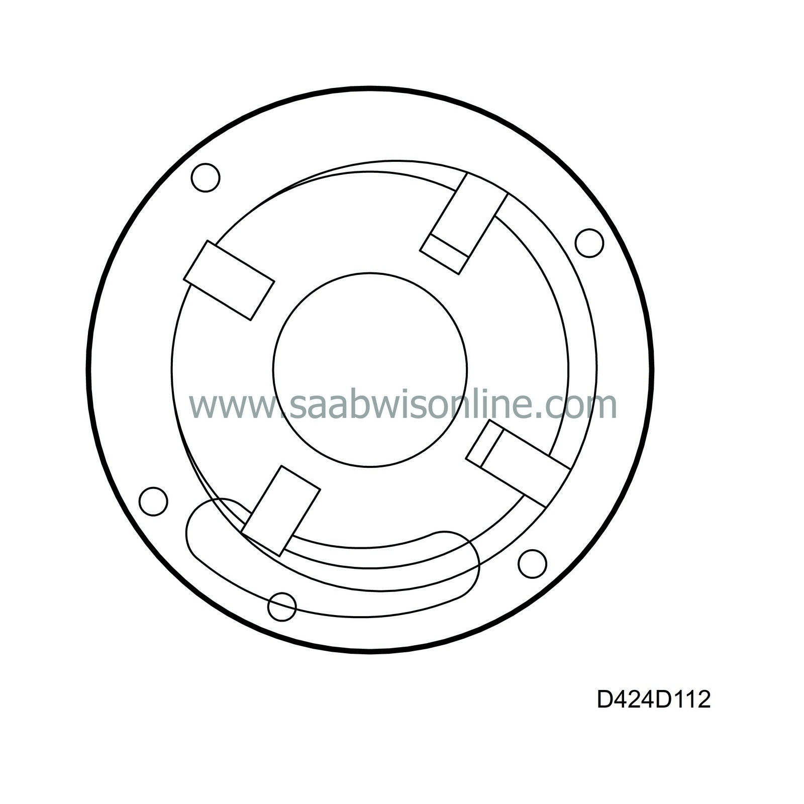
High-pressure pump
The high-pressure pump is a two-cylinder radial piston pump. Its concept is that a cam ring, which is normally stationary, can be moved to adjust the start of pressure build-up. The distributor shaft with cylinders and pistons revolves inside the cam ring.A coupling is fitted in a recess in the diesel pump drive shaft that engages in the high-pressure pump distributor shaft. When the pump shaft rotates, the coupling drives the distributor shaft.
There is a hole going radially through the distributor shaft in which two pistons act like pump pistons. They are connected to roller holders that control the rollers running over the cam ring ridges.
When the distributor shaft rotates, the cylinders and pistons are turned relative to the cam ring. As the rollers pass the cam ridges, the roller holders and pistons are forced towards the centre of the distributor shaft. When this happens, the volume between the pistons is reduced and a powerful increase in pressure is obtained, provided the control valve needle remains closed.
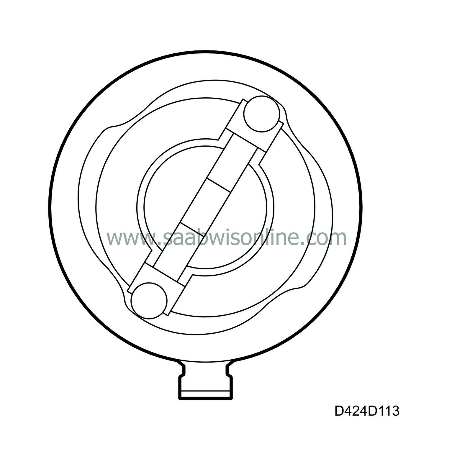
| Fuel quantity control |
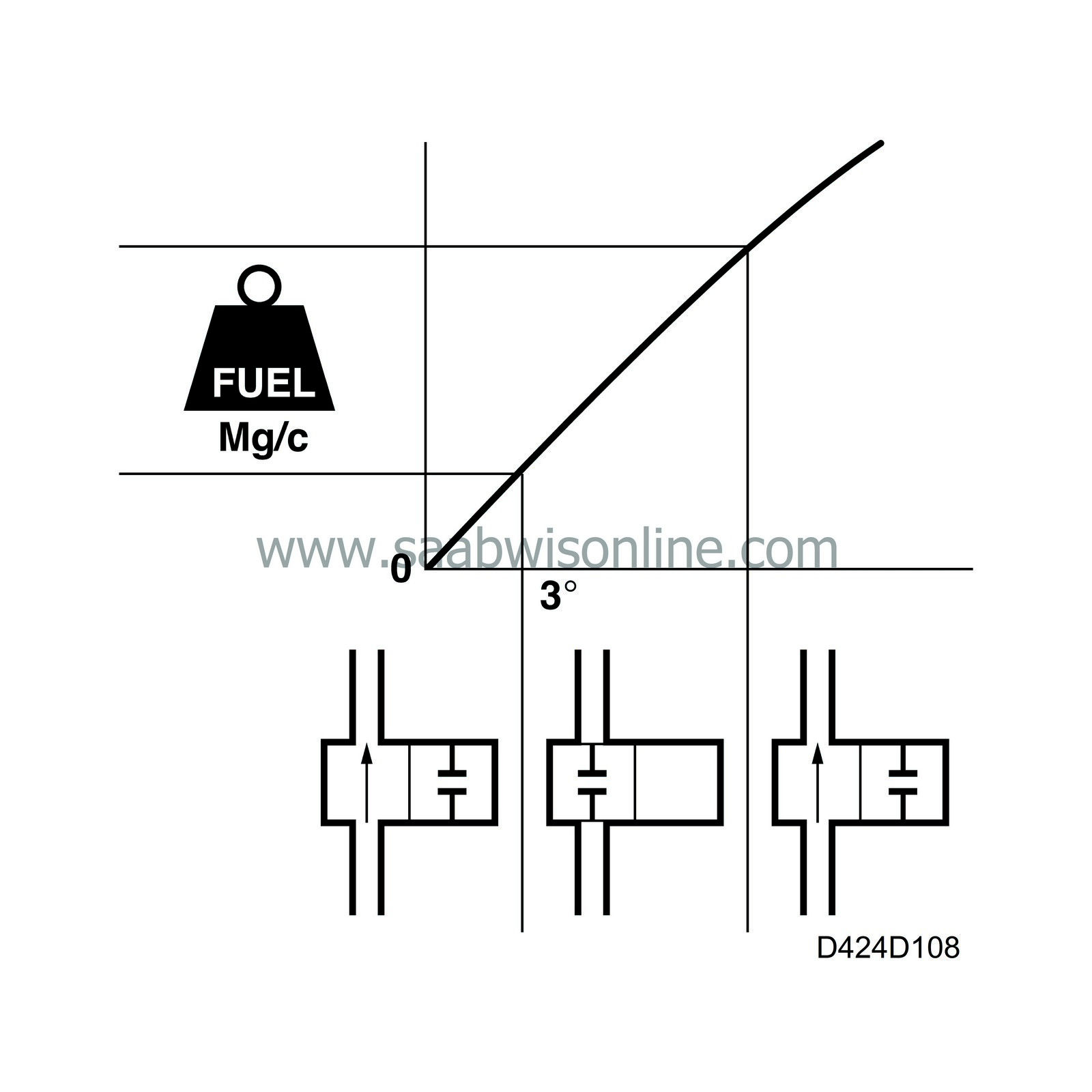
To enable the pump control module to determine the injected fuel quantity for each combustion, it reads "Requested fuel quantity in mg/combustion” on the P-bus. The bus message is converted in the pump control module from mg/combustion to a time period during which the control valve needle is to be closed. This time period is proportional to the stroke used by the cam ring and consequently also to the injected fuel quantity.
The pump control module compensates the value for "Requested fuel quantity in mg/combustion" depending on the fuel temperature, amongst other things. The pump control module compensation means that the value for "Requested fuel quantity in mg/combustion” is not necessarily the actual injected fuel quantity.
In order for the other systems in the car, besides the pump control module, to know how much fuel is being used, the pump control module sends bus message "Control valve closing time at previous injection" expressed in degrees for the pump cam. The engine control module reads this message and converts the value into a fuel consumption signal.
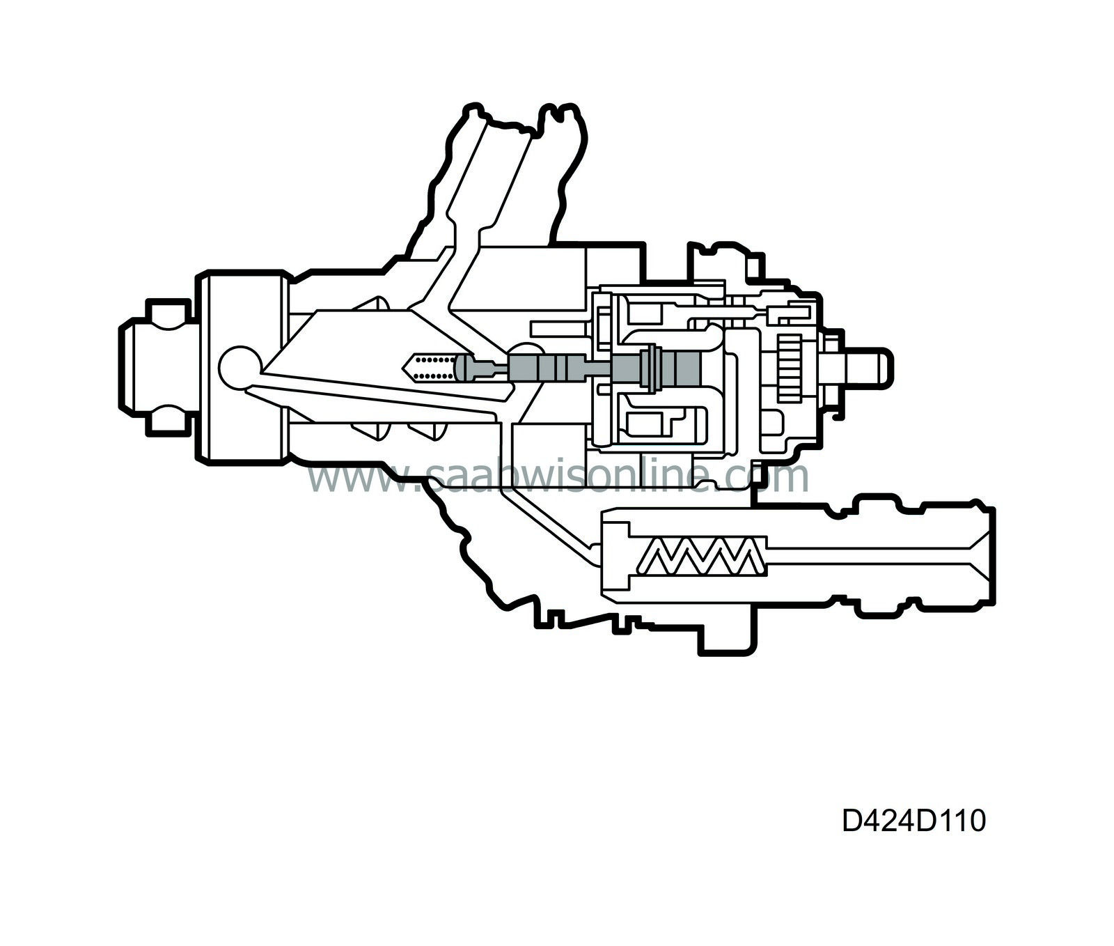
The task of the fuel quantity control is to make sure that the requested fuel quantity from the pump control module is supplied to the nozzles. The injected quantity is controlled in the high-pressure pump in the following way:
The control valve needle is fitted to the back of the distributor shaft and the high-pressure control valve in the pump housing.
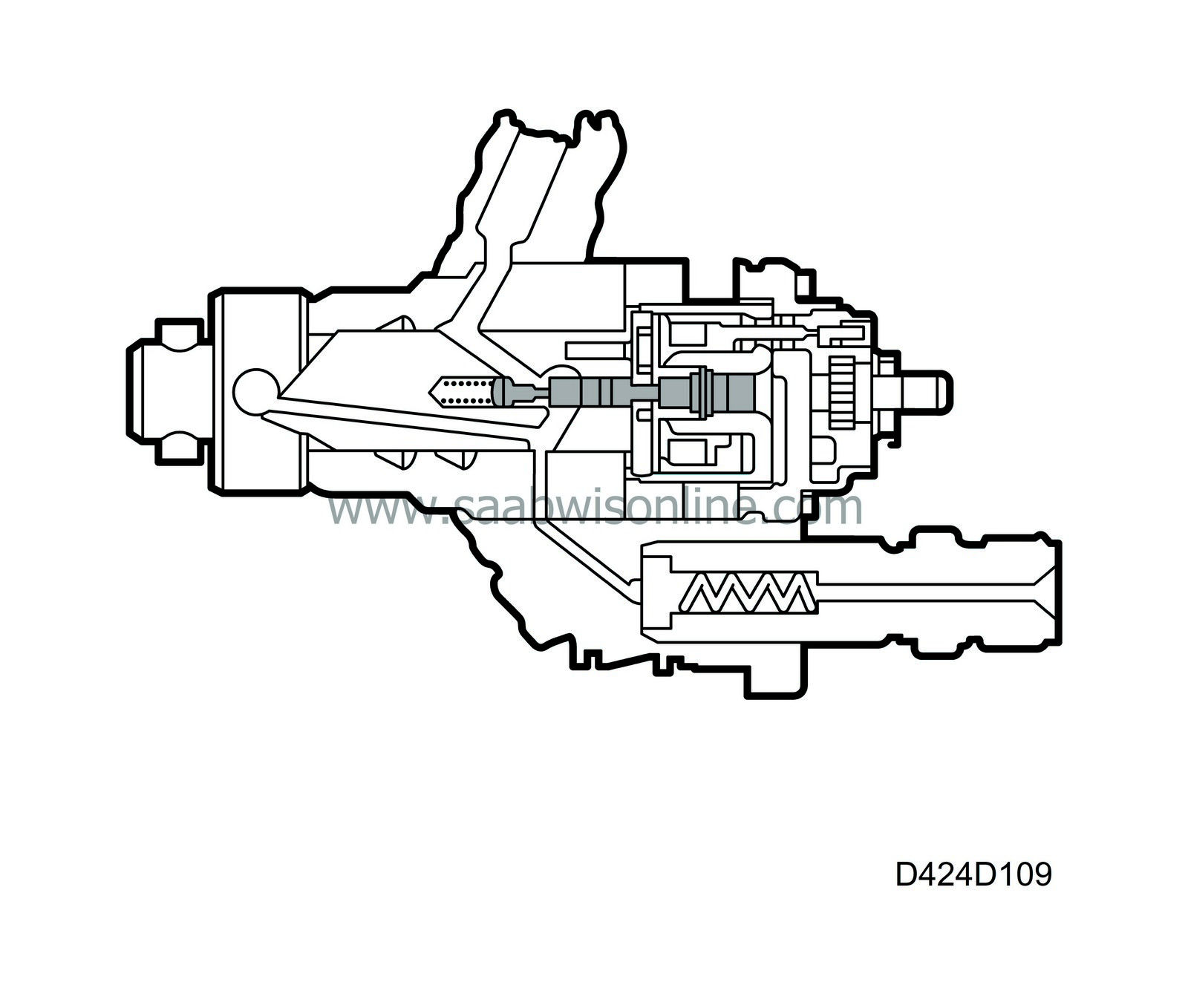
| 1. |
Pressure build-up starts with the high-pressure control valve pressing the control valve needle into its closed position so that the inlet passage from the pump housing to the high-pressure pump inlet closes. This takes place exactly when the rollers have started to ascend onto the ridges of the cam ring.
|
|
| 2. |
When this takes place, the distributor shaft is in a position where its outlet from the high-pressure pump is right in front of the passage leading to the injector pipe for the cylinder that is next in turn to receive fuel.
|
|
| 3. |
As the distributor shaft continues to rotate, the pump pistons will be pressed towards the centre of the distributor shaft. The resulting increase in pressure will, after a certain delay, be sufficient to exceed the opening pressure of the nozzle. When this happens, the injection into the combustion chamber starts (injection start).
|
|
| 4. |
When the time period corresponding to the desired injection quantity has expired, the control valve and control valve needle move back approx. 0.1 mm, releasing the pressure in the pump chamber.
|
|
| 5. |
When the rollers have passed top dead centre of the cam ridges, they move out again and the pump chamber is filled with new fuel ready for another pump cycle.
|
|
This process is repeated for each cylinder whose turn it is to fire.
| Adjusting the start of the pressure build-up |
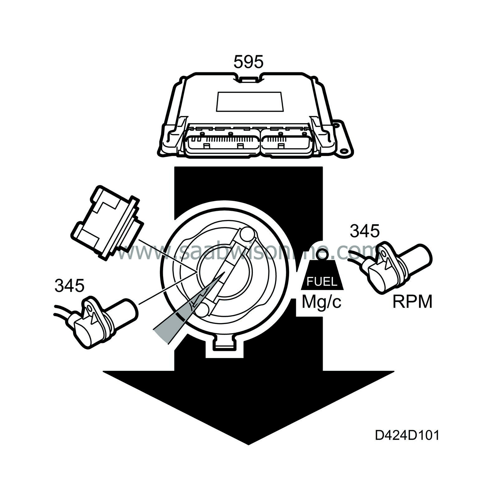
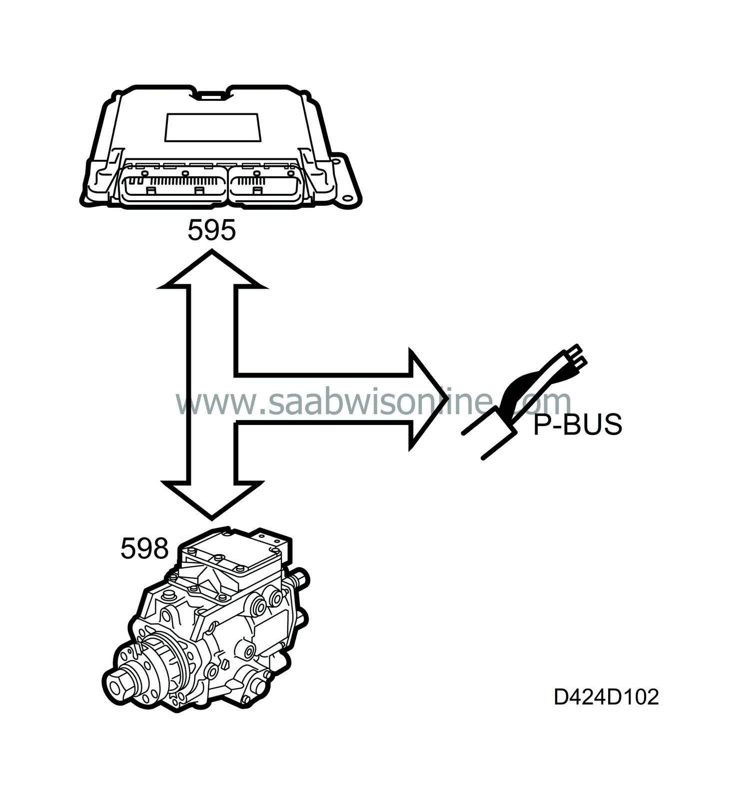
There is always a certain tolerance in the pump installation compared with the top dead centre of the engine. Likewise, the drive chain will stretch after a time in operation and further increase the internal tolerance. The EDC 15 injection system with VP44 diesel pump can compensate for this, ensuring that pressure build-up always takes place at the correct crankshaft angle before top dead centre.
The engine control module sends the following bus messages to the pump control module:
| • |
"Requested start of pressure build-up" in crankshaft degrees
|
|
| • |
"Requested start of pressure build-up” in camshaft degrees
|
|
| • |
"Requested fuel quantity” in mg/combustion
|
|
| • |
"Crankshaft speed" in rpm
|
|
| Setting the start of pressure build-up |
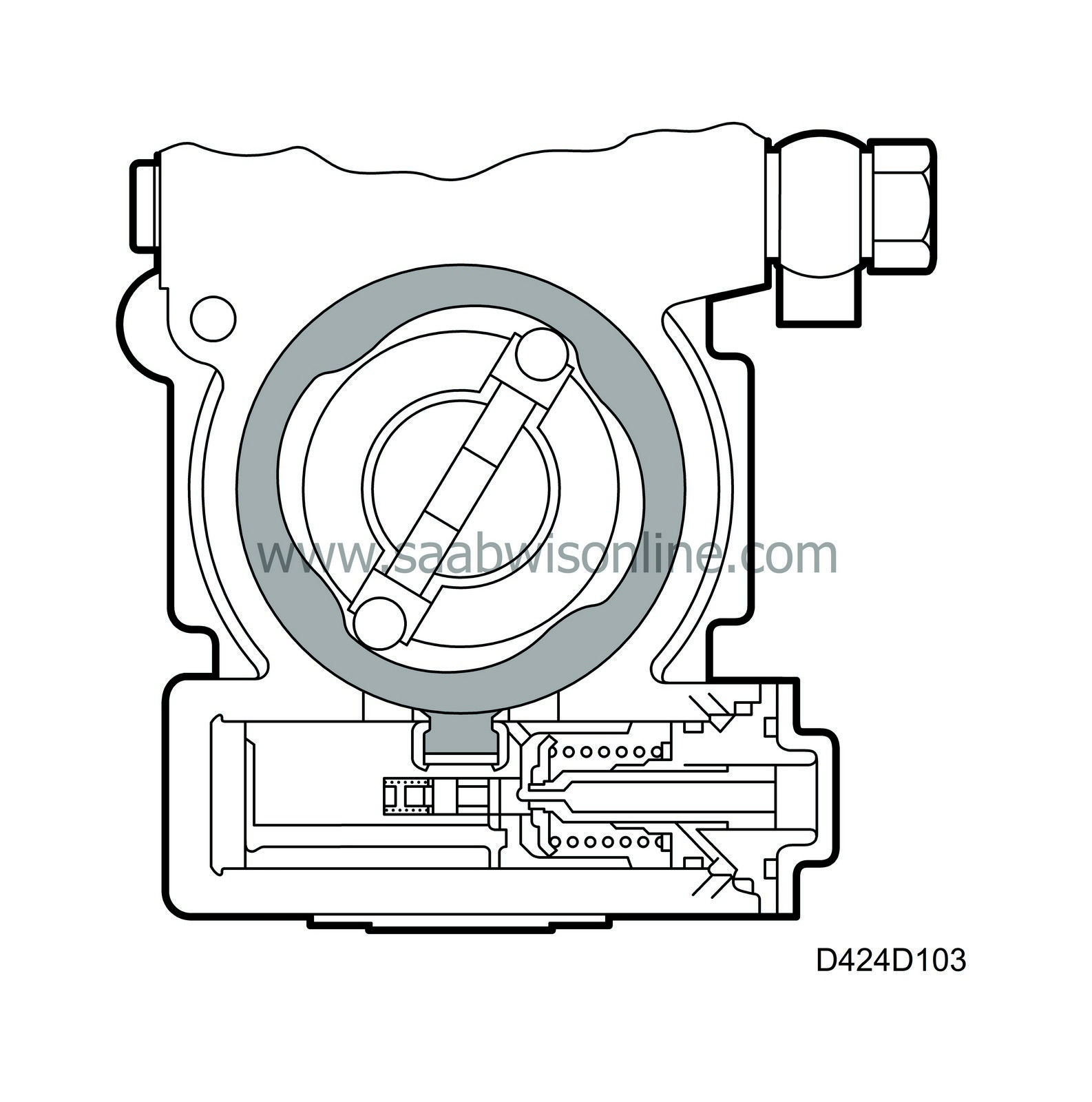

If the engine is to operate optimally, it is very important that the fuel is supplied to the combustion chamber at exactly the right moment. The moment for the injection start is measured in crankshaft degrees before top dead centre.
From the moment the accumulation of pressure starts in the pump until the start of the injection into the combustion chamber, there is a delay that affects when the start of the pressure build-up should take place. This is so that the correct moment for the start of the injection can be obtained. The delay is measured in crankshaft degrees and is the difference between start of pressure build-up start and injection start.
The fuel pressure wave from the pump moves at the speed of sound (1480 m/s) in the fluid column in the injection pipe and causes a delay. When the pressure wave finally arrives and the fuel leaves the nozzle, meeting the air in the combustion chamber, another delay occurs before the fuel ignites. This is called the ignition lag. The length of the delays depends on the engine load, engine speed and temperature. To compensate for the delays, the engine control module must continuously adjust the starting moment for pressure build-up together with the pump control module.
The adjustment of the start of pressure build-up is performed by moving the cam ring relative to the pump housing in the same way as the vacuum adjustment of the breaker plate is performed in an old ignition distributor of an Otto cycle engine.
There is a lug on the cam ring that engages in a piston. This piston can move at right-angles to the length of the pump, moving the cam ring. Inside the piston, there is a control valve that cooperates with the timing valve to move the piston in the desired direction. So that the pump control module will know where the cam ring is in relation to the top dead centre of the crankshaft, there is a Hall sensor fitted to measure the angle. This is in mechanical contact with the moveable cam ring.
There is a toothed wheel on the pump shaft with a 3° angle between teeth. However, there is a gap of three teeth for each cylinder, making 27 teeth between cylinders. By comparing the information from the crankshaft position sensor with that from the angle sensor in the pump, the pump control module can calculate where the cam ring is in relation to top dead centre.
The adjuster piston for the pressure build-up start position is spring-loaded on one side with diesel oil pressure acting on the other. The pressurized diesel oil is controlled by the timing valve for the pressure build-up starting position. By changing the timing ratio, the pump control module can adjust the cam ring to the desired position.
The feed pump pressurizes the whole inside of the pump and it is from that pump that oil is passed to the timing valve. The oil that is not needed behind the piston is released to the suction side of the feed pump.
| Start of pressure build-up relative to the pump camshaft |

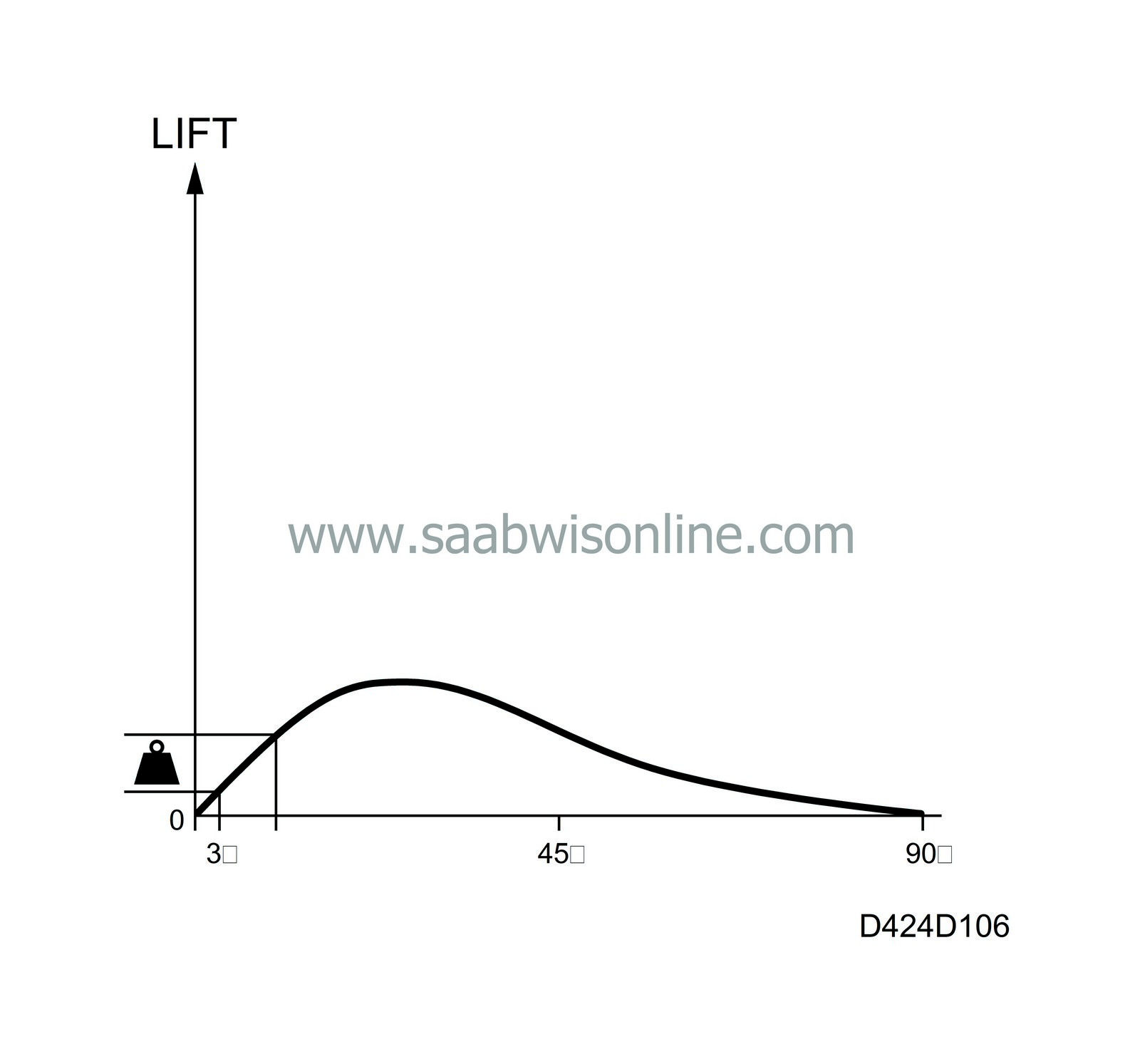
The value of the bus message "Requested start of pressure build-up in camshaft degrees" specifies where the control valve should close and the start of pressure build-up should take place in relation to the bottom dead centre of the pump cam ring. The "pump cam ring bottom dead centre" is called "cam ring zero" below.
Example: 3° means that the solenoid valve closes 3 degrees after cam ring zero.
The position of the pump cam ring is made available to the pump control module by the pump control module registering when the tooth gap passes the angle sensor. The angle sensor is mounted in a precise position in relation to the bottom dead centre of the cam ring and therefore the pump control module can detect the position of the cam ring.
| Start of pressure build-up relative to the crankshaft |

The value of the bus message "Requested start of pressure build-up in crankshaft degrees" specifies where start of pressure build-up should take place in relation to the top dead centre of the engine.
Since the gaps that the crankshaft position sensor detects on the crankshaft are displaced relative to top dead centre, the difference in crankshaft degrees is programmed in the pump control module.
The pump control module is informed of the position of bottom dead centre for the pump cam ring relative to top dead centre for the engine from the bus message "Crankshaft speed in rpm" being sent in a precise relationship to top dead centre for the engine. The bus message “Camshaft speed” is sent when the gap on the crankshaft passes the crankshaft position sensor. The gap is displaced by 13° relative to top dead centre for the engine. The control module is programmed for this displacement and therefore knows exactly when top dead centre is reached.
Example: Start of pressure build-up relative to the crankshaft is 23°, which means that the pump control module, aided by the control valve for injection start, moves the cam ring relative to the crankshaft to a position corresponding to 23° between start of pressure build-up and top dead centre for the crankshaft.
Consequently, in this example, the difference between cam ring zero and engine top dead centre is: Start of pressure build-up relative to the pump cam ring 3° (which is the same as 6° relative to the crankshaft) + start of pressure build-up relative to the crankshaft 23°. So the pump control module in this example must adjust the cam ring so that cam zero falls 29° (6°+23°) before engine top dead centre.


