SAAB WIS ONLINE

Boost pressure control

Boost pressure control


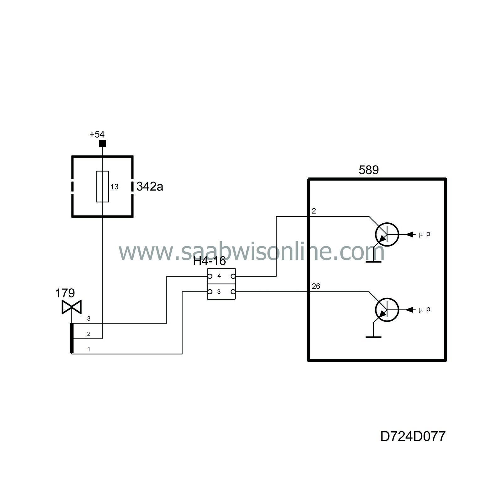
Boost pressure control takes place using a 2-coil, 3-way solenoid valve connected with hoses to the turbo wastegate, compressor outlet and compressor inlet.

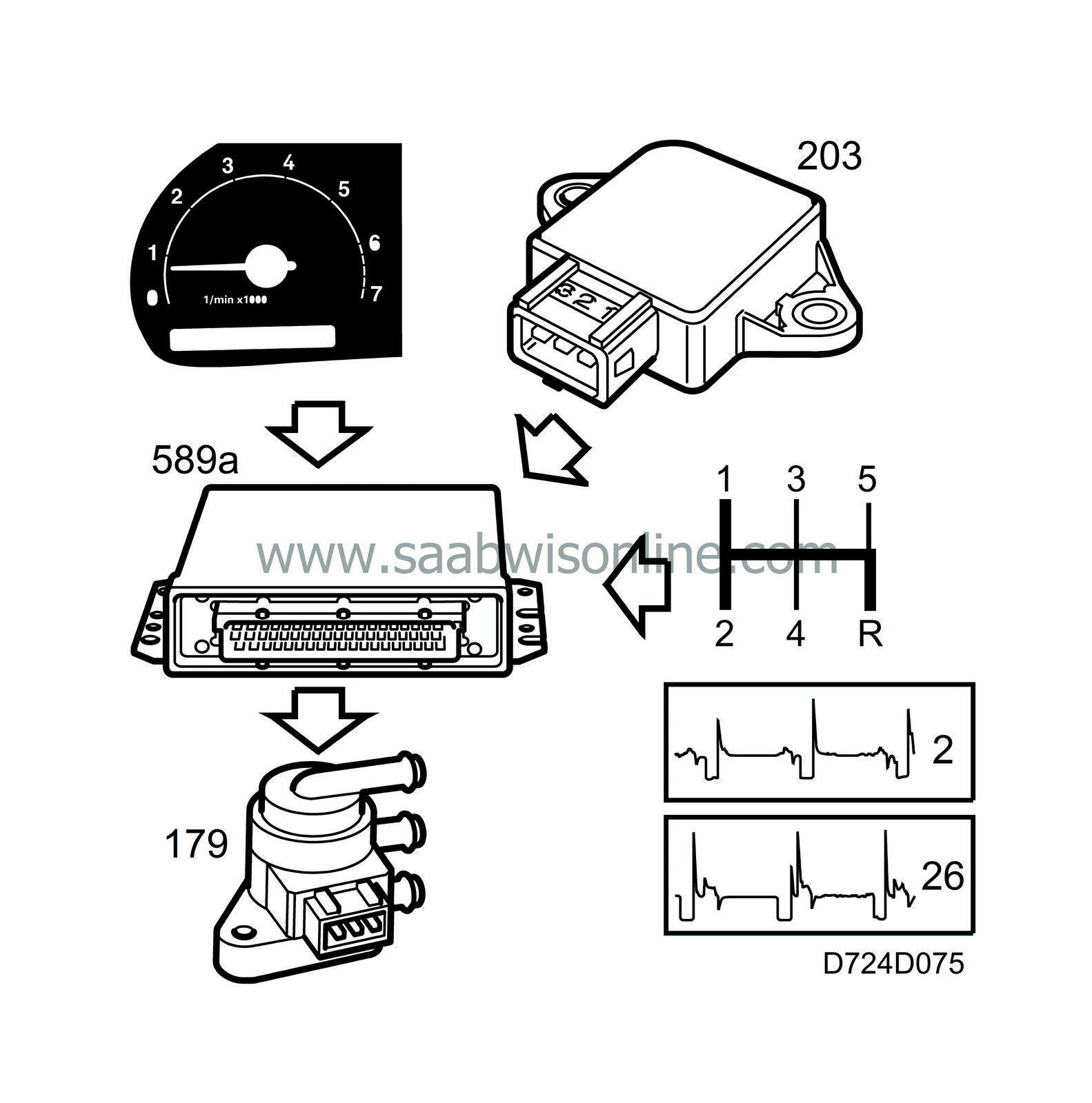
The solenoid valve is powered from +54 via fuse 13 and is controlled from control module pin 26 and pin 2. The control current is a PWM at 90 Hz below 2500 rpm and 70 Hz above 2500 rpm. The change in frequency at 2500 rpm is to avoid resonance in the air hoses.

By grounding pin 2 for longer than pin 26, the boost pressure will drop and vice versa, by grounding pin 26 for longer than pin 2, the boost pressure will rise.

To be able to regulate the boost pressure, the control module must first calculate a requested pressure, i.e. a value the system should try to attain. This is done as follows:

A requested boost pressure for every engine speed and throttle position is programmed in the control module memory. The pressure for each engine speed is chosen so that the desired torque curve is applied to the engine at wide open throttle.

The requested pressure will be limited in the following cases:


There is a maximum value for 1st, 2nd and reverse gear that is engine speed dependent. The control module calculates the gear position by comparing vehicle speed with engine speed.

A maximum value is set when knocking occurs that is dependent on the average ignition retardation on all cylinders.

When vehicle speed reaches 230 km/h (235 km/h for B204R).


In the following cases, there will be no boost pressure request at all (basic charging pressure):


When the brake pedal is depressed and the control module receives B+ on pin 15.

When certain diagnostic trouble codes have been generated (throttle position sensor, pressure sensors, knock signal or boost pressure control) or if battery voltage is low.

The following function is not implemented in the software at present: When cruise control is active and control module pin 36 is grounded.


Once the requested boost pressure is finally calculated, it is converted to a PWM to govern the boost pressure control valve.

The control module then makes sure the current pressure reading from the pressure sensor corresponds with the requested. If necessary, the PWM ratio will be adjusted by multiplying it with a correction factor.

The correction factor (adaptation) is stored in the control module memory and is always included in the calculation of the PWM ratio.

This is done so that the current pressure will equal the requested as soon as possible after a change in load.

Diagnosis


There is no diagnosis for a break or short in the circuit to the boost pressure control valve.

If the intake pressure is higher than requested, diagnostic trouble code P1549 will be generated.


System reaction to a fault


Basic charging pressure

Note

There is no diagnosis for faults where the requested boost pressure cannot be attained. If a boost pressure control malfunction is suspected, Tech 2 should be used to see if a boost pressure limiting function is active first. Note that Tech 2 will not indicate the presence of a limitation for low gear. If Tech 2 indicates U for the gear in question then the vehicle speed signal is probably absent.

If there are no active functions limiting the requested pressure and the correct gear is indicated then the pressure specified in technical data should be attainable during a road test.

The following faults will result in the boost pressure control being absent (basic charging pressure):

Break in the lead from control module pin 26 or +54 supply to the valve.

Defective charge air control valve.

The following faults will cause the boost pressure to be higher than the requested. The control module will then stop fuel injection as a safety precaution.

Break in the lead from control module pin 2.

Defective charge air control valve.

Break in any of the hoses marked W or C.

Defective wastegate or diaphragm box.

Control module outputs on pins 2 and 26 are not short-circuit protected. Therefore, a short-circuited valve can burn out a new control module. A burned control module can then burn out and short-circuit a new valve.

It is therefore advisable to first check that the control module is in working order before connecting a new valve.

The control module can be checked easily by connecting test lamp 86 11 857 between pins 2 and 1 on the control module and pins 2 and 3 in the valve's female connector respectively and then racing the engine. The control module is in working order if the test lamp flickers.

Before performing a road test after completed repairs, it is advisable to zero boost pressure adaptation, either with Tech 2 activation or by terminating the current to the control module. If a fault causing low boost pressure has been rectified, the boost pressure adaptation is probably at maximum. This may activate the pressure switch during the road test before the adaptation has returned to normal values unless it has been zeroed first.