Fuel injection
| Fuel injection |
Injectors
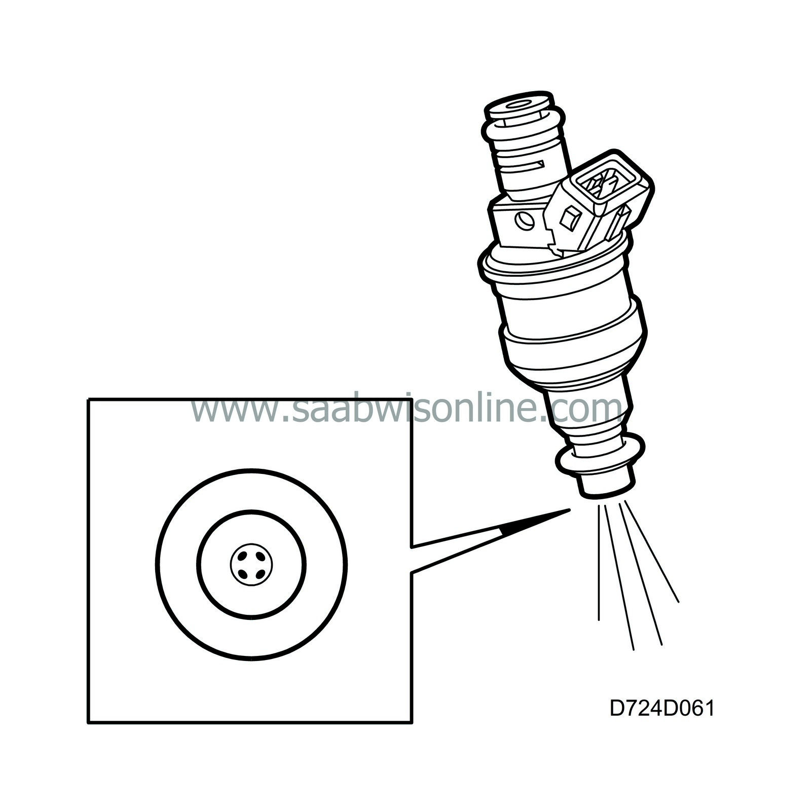
The injectors are solenoid type with needle and seat. They open when current passes through the coil and are closed by a powerful spring when the current is stopped.To obtain optimum combustion and cleaner emissions, the injectors have 4 holes to give a good distribution of the fuel.
The jets of fuel are very precisely set (two jets on each inlet valve). This puts great demands on how the injectors are positioned. To ensure their correct positioning, they are fixed in pairs on special mounting brackets between cyl. 1-2 and cyl. 3-4.
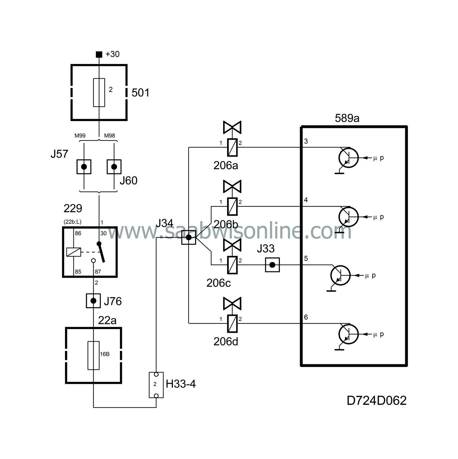
The injectors are supplied with current from the main relay, while the control module grounds them as follows:
| • |
injector 1 is grounded on pin 3
|
|
| • |
injector 2 is grounded on pin 4
|
|
| • |
injector 3 is grounded on pin 5
|
|
| • |
injector 4 is grounded on pin 6
|
|
| Diagnosis |
| • |
If there is a break in the circuit to an injector, the cylinder in question will not fire and a misfire trouble code will be generated.
|
|
Pre-injection
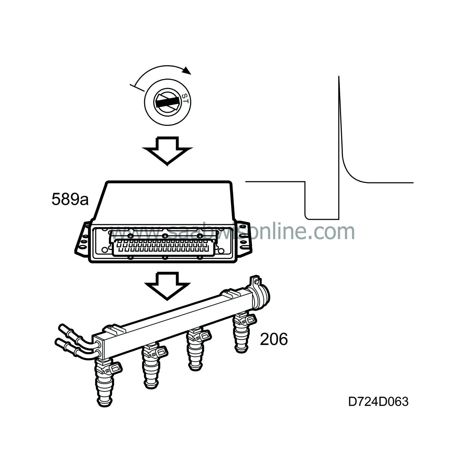
When the ignition is turned on, the main relay and fuel pump relay will be activated for a few seconds. As soon as the control module detects the crankshaft rotating, an injection that is dependent on coolant temperature takes place on all 4 injectors simultaneously. This is to obtain short starting times.If the engine is started and then turned off shortly afterwards, a new pre-injection will be obtained after waiting 45 seconds with the ignition off.
Calculation of injection duration
To determine the amount of fuel to be injected into each manifold pipe, the control module calculates the air mass drawn into each cylinder.The calculation is performed as follows (each cylinder in the B204L holds 0.5 l): 0.5 l air with a certain density has a determined weight. The density is calculated using the pressure and temperature in the intake manifold. When the current air mass has been calculated it is divided by 14.7 to convert it to fuel mass per combustion to be injected.
As the flow capacity of the injector and the density of the fuel are known (pre-programmed values), the control module is able to calculate the injection duration.
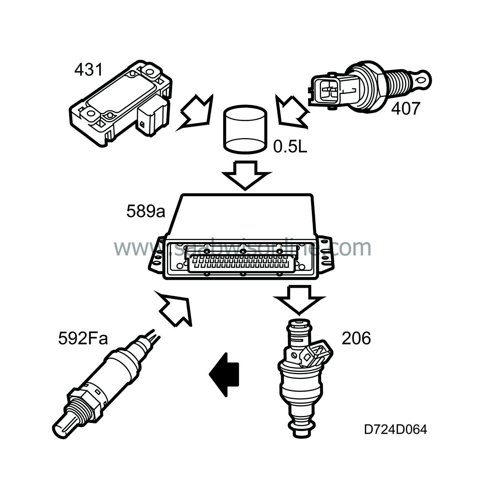

The injection duration is corrected with oxygen sensor 1 so that Lambda=1.0 is attained. Closed loop is disengaged and full load enrichment takes place during fast acceleration to provide maximum performance. As the accelerator is depressed, acceleration enrichment will take place and when the accelerator is released, deceleration "lean-out". Fuel enrichment dependent on the coolant temperature takes place during cold starting and warm-up before closed loop is engaged.
Injection duration with warm engine and normal battery voltage can vary between approx. 2.5 ms at idling speed to approx. 18-20 ms at full engine torque.
Closed loop
In order for the catalytic converter to function correctly, the fuel/air mixture must be stoichiometric.This means that the mixture must not be too rich or too lean but exactly 14.7 kg air to 1 kg fuel (Lambda=1).
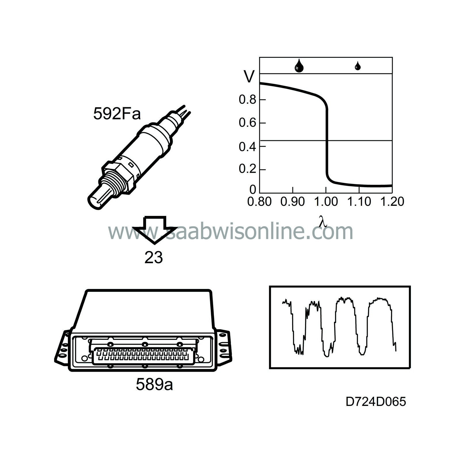
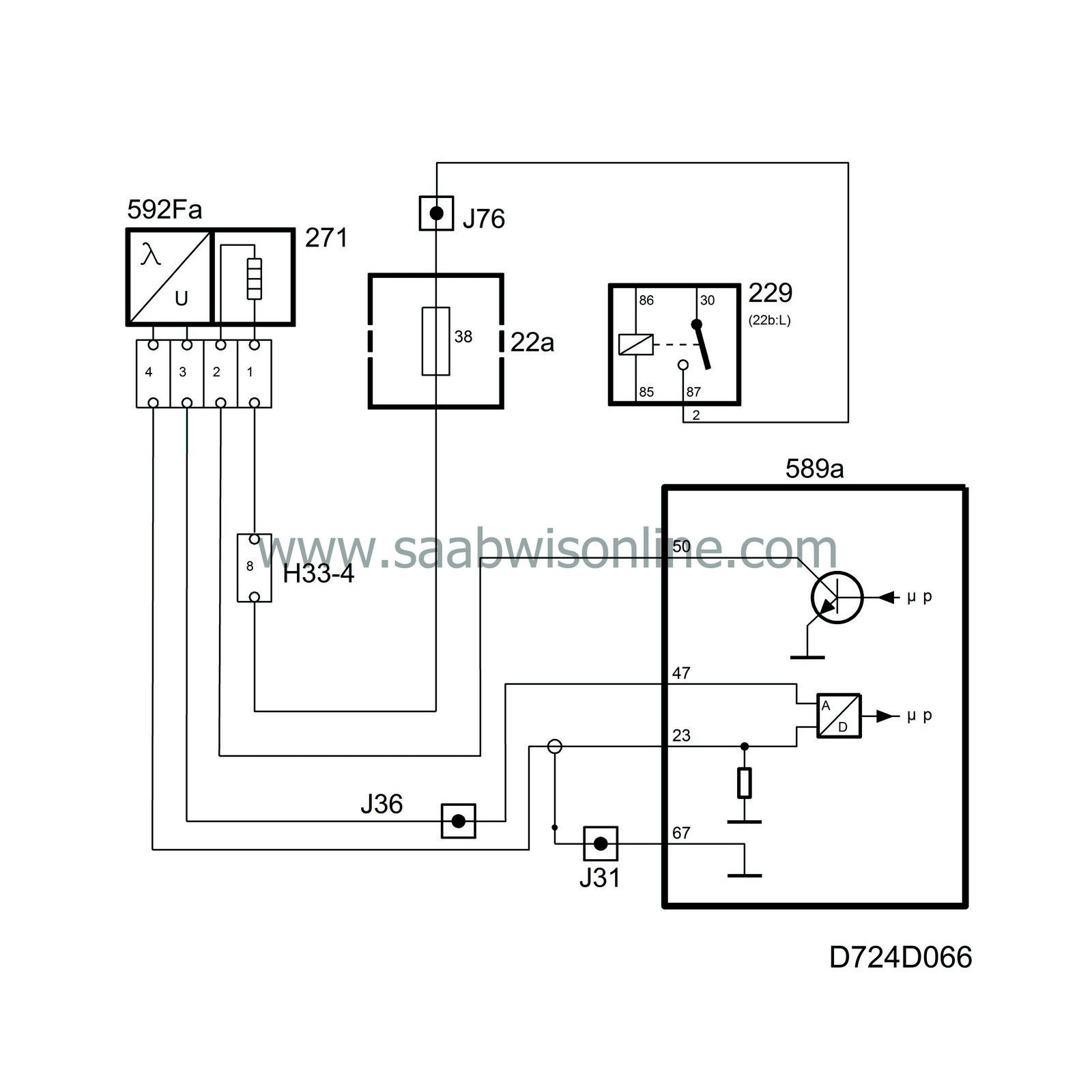
Because of this, the system is equipped with an oxygen sensor mounted in the front section of the exhaust pipe. The sensor is connected to control module pin 23 and is grounded from control module pin 47.
The exhaust gases from the engine flow past the oxygen sensor. The oxygen content in the exhaust gases is measured by a chemical reaction. The output voltage of the oxygen sensor is proportional to the current oxygen content.
| Important | ||
|
The oxygen sensors receive reference oxygen from the surrounding air via the connecting cables. Because of this, contact spray or grease must not be used on the oxygen sensor connectors. |
||
If the engine is running too rich (Lambda below 1), the sensor output voltage will be approx. 0.9 V.
If the engine is running too lean (Lambda above 1), the sensor output voltage will be 0.1 V. The sensor voltage changes very rapidly once Lambda passes 1.
The control module continuously corrects the injection duration so that Lambda=1 is always obtained.
In order to supply voltage quickly after start, the oxygen sensor must be pre-heated. Pre-heating is supplied with B+ from the main relay via fuse 38 and is grounded via control module pin 50. The control module estimates the exhaust temperature based on the load and engine speed. Pre-heating is disengaged if the exhaust temperature is high.
Closed loop is engaged 640 engine revolutions after start if the coolant temperature exceeds 18 C (64 F) under partial load or 32 C (90 F) at idling speed.
| Diagnostics, oxygen sensor 1 |
| • |
If the current in the oxygen sensor pre-heating circuit is too low, diagnostic trouble code P0135 will be generated.
|
|
| • |
If the current in the oxygen sensor pre-heating circuit is too high, diagnostic trouble code P0135 will be generated.
|
|
| • |
If the sensor lead is short-circuited to ground or if there is a break, diagnostic trouble code P0131 will be generated.
|
|
| • |
If the sensor lead is short-circuited to B+, diagnostic trouble code P0132 will be generated.
|
|
| • |
If the sensor reacts too slowly to changes in the fuel-air mixture or if its voltage transition is too far from lambda 1, diagnostic trouble code P0133 will be generated.
|
|
System reaction to a fault
| • |
Closed loop blocked.
|
|||||||
| Diagnostics, closed loop |
| • |
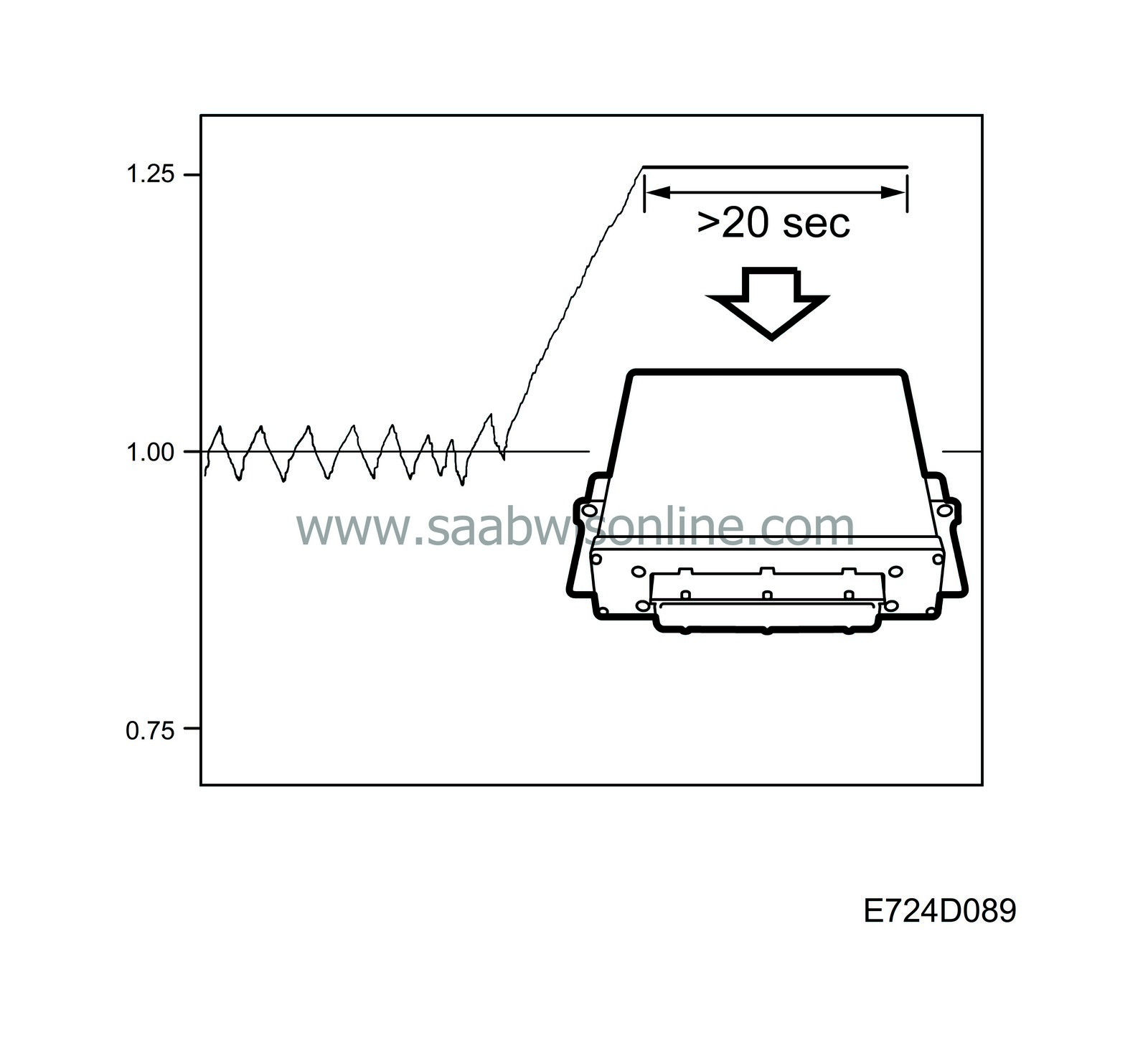
With a correction factor of 1.25, the oxygen sensor will still read a lean air/fuel mixture despite the amount of fuel being increased as much as possible. If this condition persists for longer than 20 seconds, diagnostic trouble code P1171 will be generated. The fault may be caused by:
|
|
| - |
Defective pressure sensor.
|
| - |
Low fuel pressure.
|
| - |
Incorrect injectors or control module fitted.
|
| - |
Blocked injectors.
|
| • |
Correspondingly, with a correction factor of 0.75, the oxygen sensor will still read a rich air/fuel mixture despite the amount of fuel being reduced as much as possible. If this condition persists for longer than 20 seconds, diagnostic trouble code P1172 will be generated. The fault may be caused by:
|
|
| - |
Defective pressure sensor.
|
| - |
Purge valve stuck open.
|
| - |
Incorrect injectors or control module fitted.
|
| - |
Fuel pressure too high.
|
Adaptation
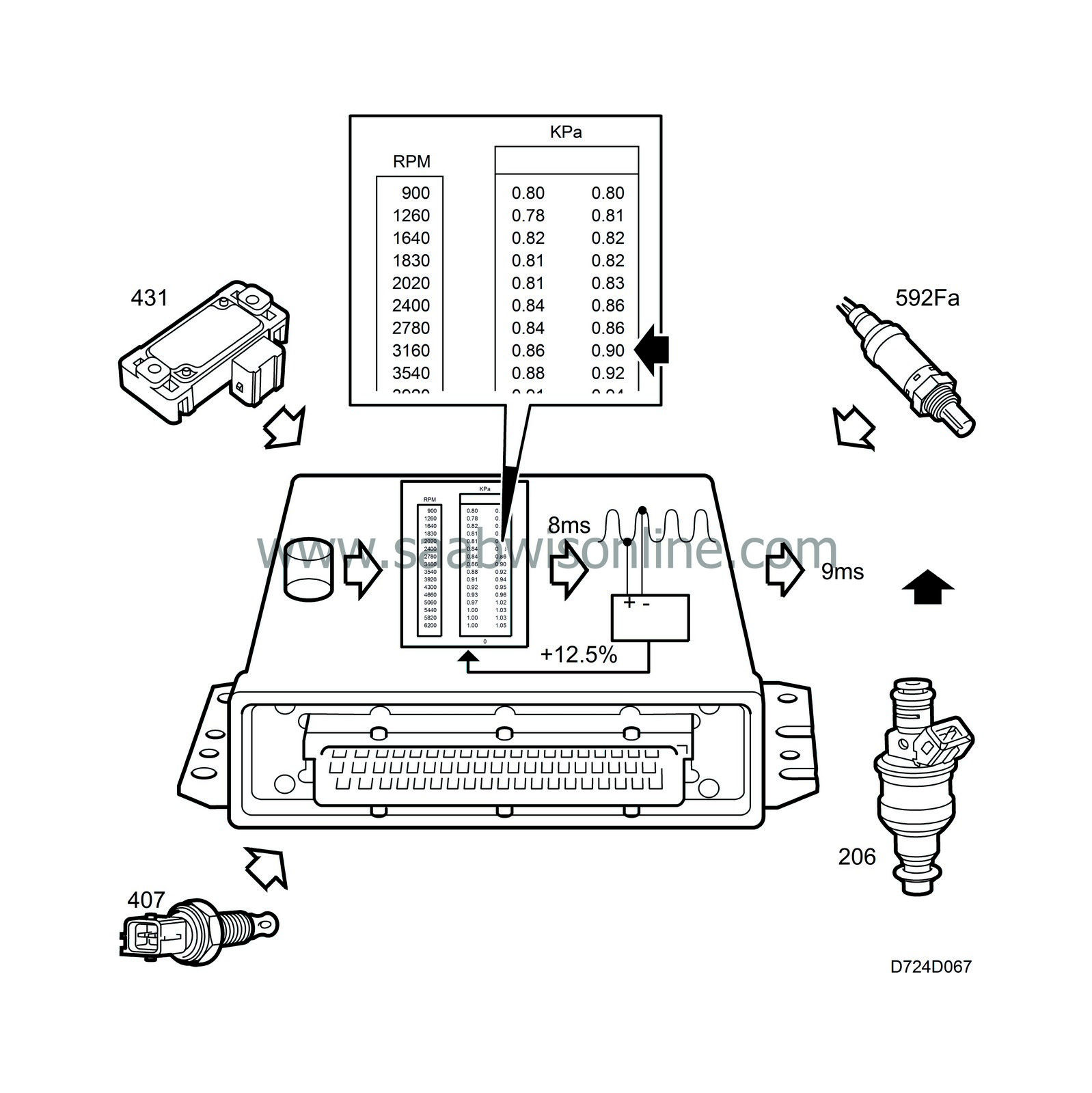
For reasons of space, the figure above shows only two columns of pressure values.The control module first calculates the injection duration based on the pressure and temperature in the intake manifold.
The injection duration is then corrected by multiplying it with a correction factor taken from the main fuel matrix, which is dependent on pressure and engine speed. Injection duration must be corrected as the engine's fill factor changes with engine speed.
A final correction is performed using closed loop so that Lambda=1 is obtained.
Closed loop can adjust the calculated injection duration with ±25 %.
Using closed loop, the control module can change the correction factor in the main fuel matrix to achieve good driveability, fuel consumption and emissions even when closed loop is not engaged. This is called adaptation.
Point adaptation
If the control module calculates injection duration to 8 ms but closed loop adjusts it to 9 ms because the fuel pressure in the car is somewhat low, the control module will "learn" the new injection duration. This is achieved by changing the correction factor for the current engine speed and load point in the main fuel matrix so that the resulting injection duration becomes 9 ms. The correction factor in this example will be increased by 9/8 (+12.5%).Point adaptation can change the points in the main fuel matrix with ±25 %. Adaptation takes place for 30 seconds every 5 minutes provided closed loop is active and the coolant temperature is above 64c (147F). The EVAP canister purge valve is de-activated during adaptation.
| Diagnosis |
| • |
Point adaptation has no diagnostics and the values at the various load and engine speed points cannot be read with Tech 2.
|
|
Global adaptation
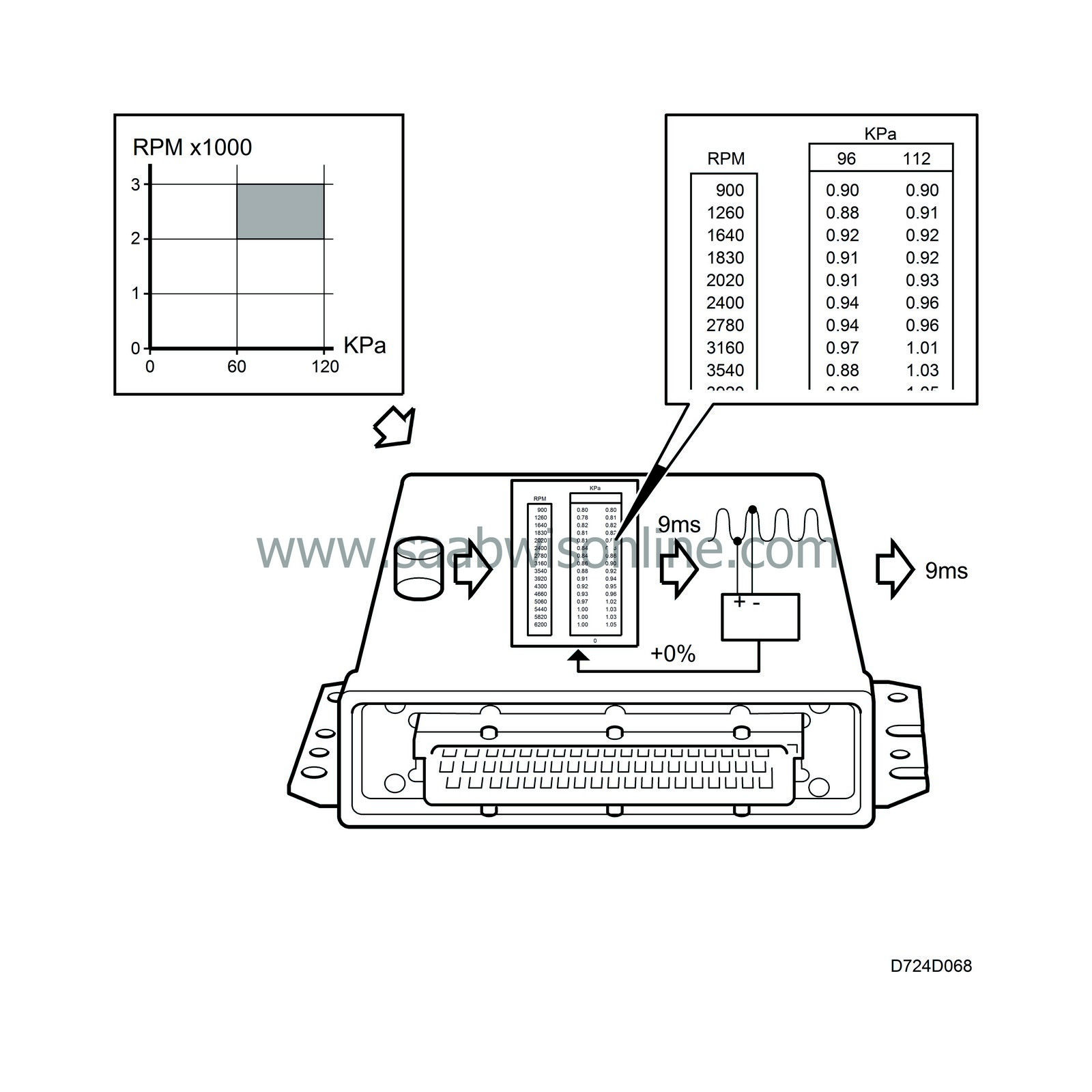
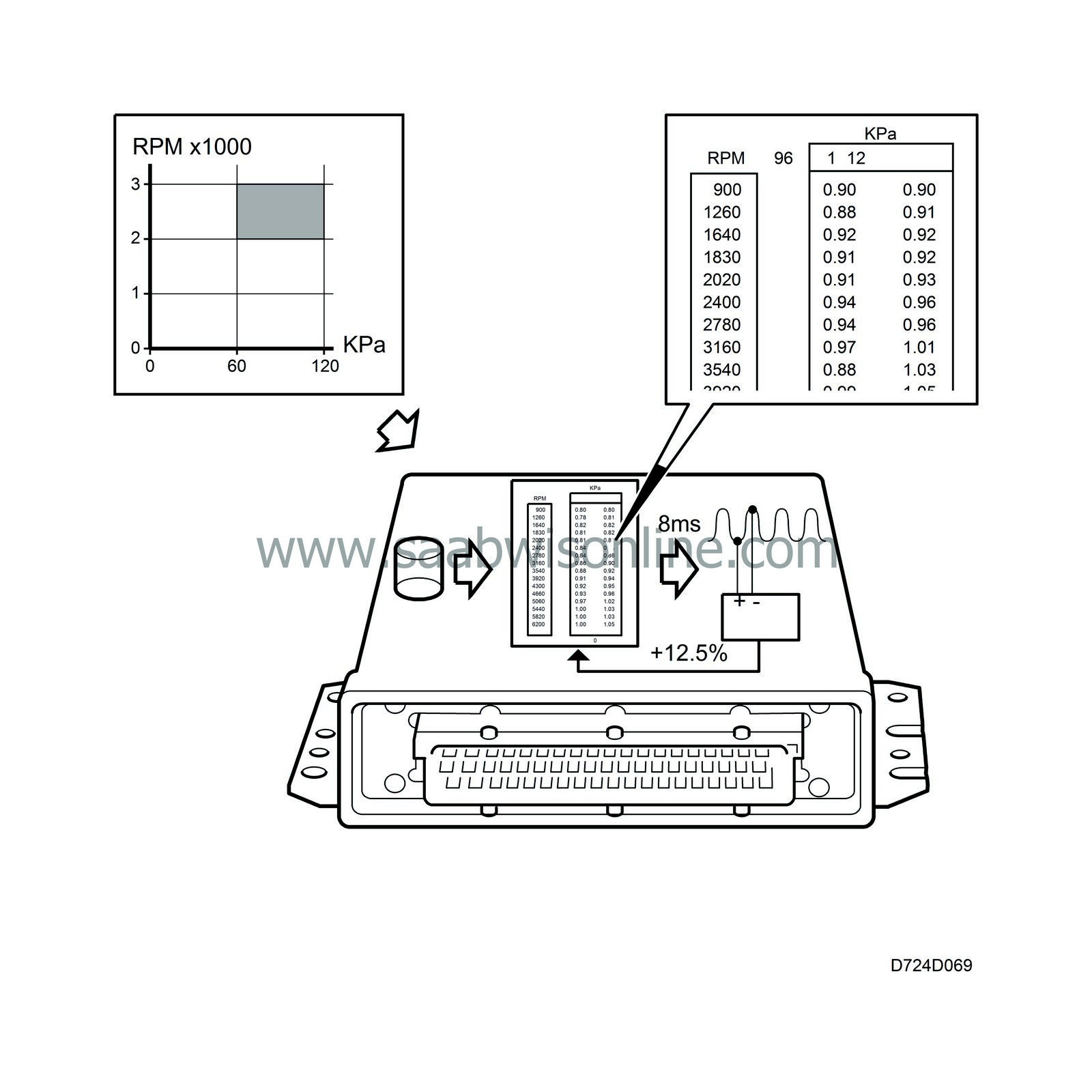
Global adaptation takes place during driving.While the engine is within a determined load and engine speed range (60-120 kPa and 2000-3000 rpm) there will not be any point adaptation, all the points in the fuel matrix will be corrected by introducing a multiplicative factor instead. Global adaptation is limited to ±25 % (Tech2 shows ±100%). Adaptation takes place for 30 seconds every 5 minutes provided closed loop is active and the coolant temperature is above 64C (147F). The EVAP canister purge valve is de-activated during adaptation.
| Diagnosis |
| • |
If the correction factor reaches 1.25, diagnostic trouble code P0171 will be generated. Tech 2 shows 100% in this case.
The fault can be caused by: |
|
| - |
Defective pressure sensor.
|
| - |
Low fuel pressure.
|
| - |
Incorrect injectors or control module fitted.
|
| - |
Blocked injectors.
|
| • |
If the correction factor reaches 0.75, diagnostic trouble code P0172 will be generated. Tech 2 shows -100% in this case.
The fault can be caused by: |
|
| - |
Defective pressure sensor.
|
| - |
Purge valve stuck open.
|
| - |
Incorrect injectors or control module fitted.
|
| - |
Fuel pressure too high.
|
Oxygen sensor 2 (after catalytic converter)
In order to diagnose the catalytic converter, an oxygen sensor is mounted after it in the exhaust system.The oxygen sensor is connected to control module pin 70 and is grounded from control module pin 47.
Sensor preheating is supplied with B+ from the main relay via fuse 38 and is grounded via control module pin 51. The control module engages preheating when the coolant temperature exceeds 50C (122F). Preheating is disengaged when the estimated exhaust temperature is high (high load and high engine speed).
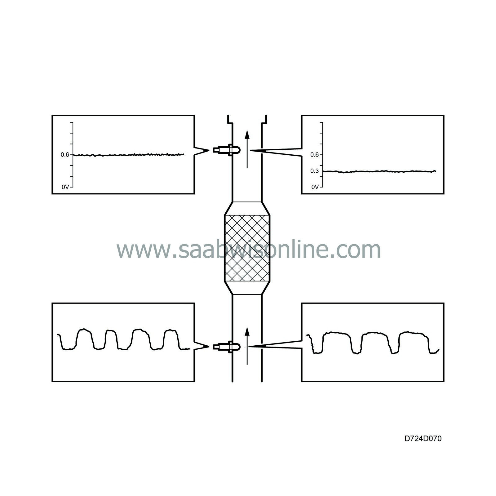
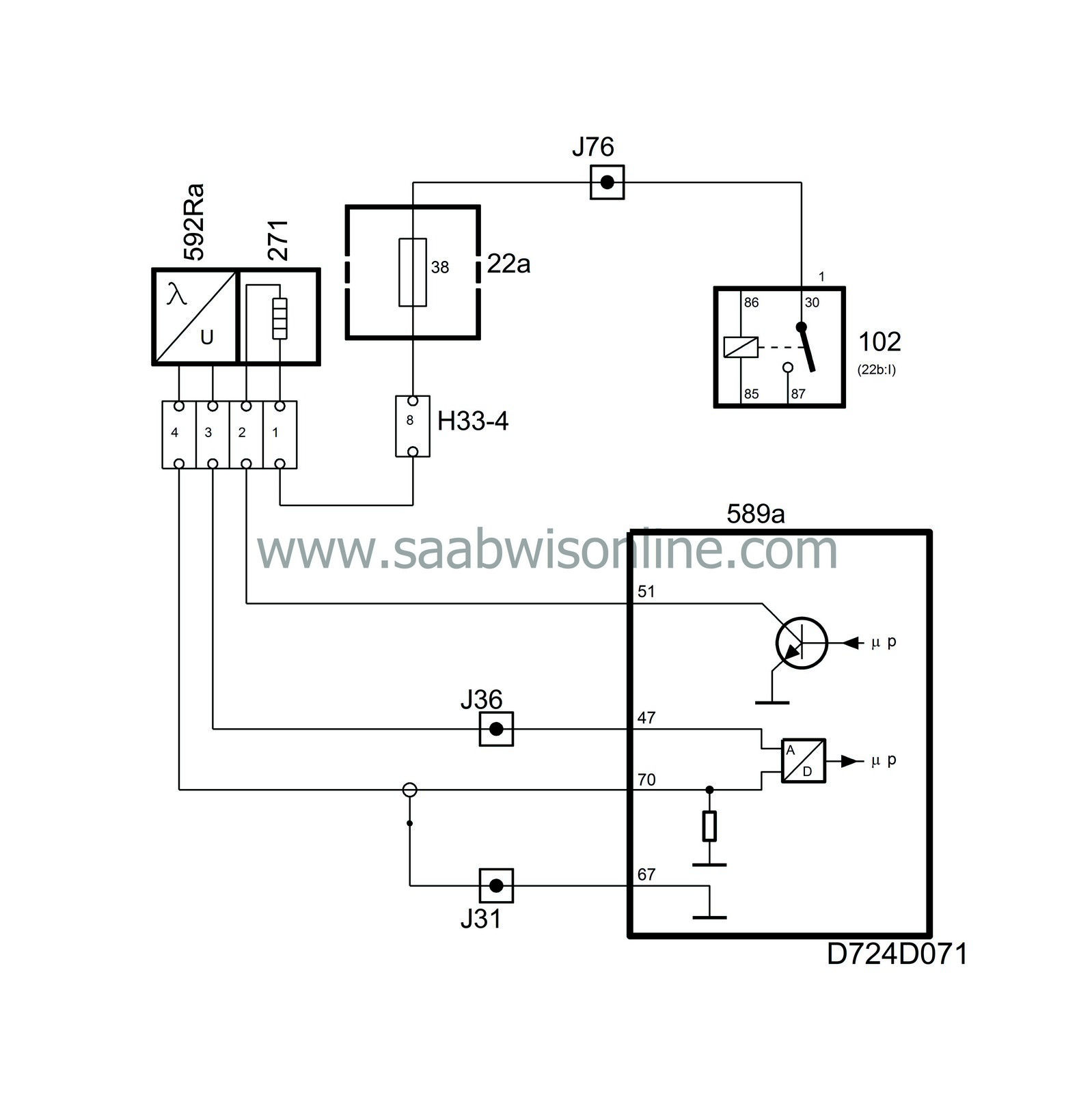
To further improve exhaust emissions, the value form the sensor is used to correct closed loop. Optimum emission values are attained when the oxygen sensor voltage is 0.6 V.
If the voltage is 0.3 V, for example, the engine will be running somewhat lean and closed loop will then be corrected so that the fuel/air mixture is kept rich for longer than it is kept lean, whereby the sensor voltage is increased.
| Important | ||
|
The oxygen sensor receives reference oxygen from the surrounding air via the connecting cables. Because of this, contact spray or grease must not be used on the oxygen sensor connector. |
||
| Diagnosis |
Oxygen sensor 2
| • |
If the current in the oxygen sensor preheating circuit is too low, diagnostic trouble code P0141 will be generated.
|
|
| • |
If the current in the oxygen sensor preheating circuit is too high, diagnostic trouble code P0141 will be generated.
|
|
| • |
If the sensor lead is short circuited to B+, diagnostic trouble code P0138 will be generated.
|
|
| • |
If there is an open circuit on any of the leads for the sensor ground or sensor voltage, or if the sensor voltage is short circuited to ground, diagnostic trouble code P0140 will be generated.
|
|
System reaction to a fault
| • |
Transition adaptation of closed loop is blocked.
|
|
Three way catalytic converter
| • |
If the catalytic converter is damaged, diagnostic trouble code P0420 will be generated.
|
|
| Note | ||
|
When oxygen sensor preheating is activated, a diagnostic trouble code indicating low preheating current will be generated as the main relay has not been activated. Diagnostic trouble codes must be cleared after completing fault diagnosis. |
Fuel shut-off
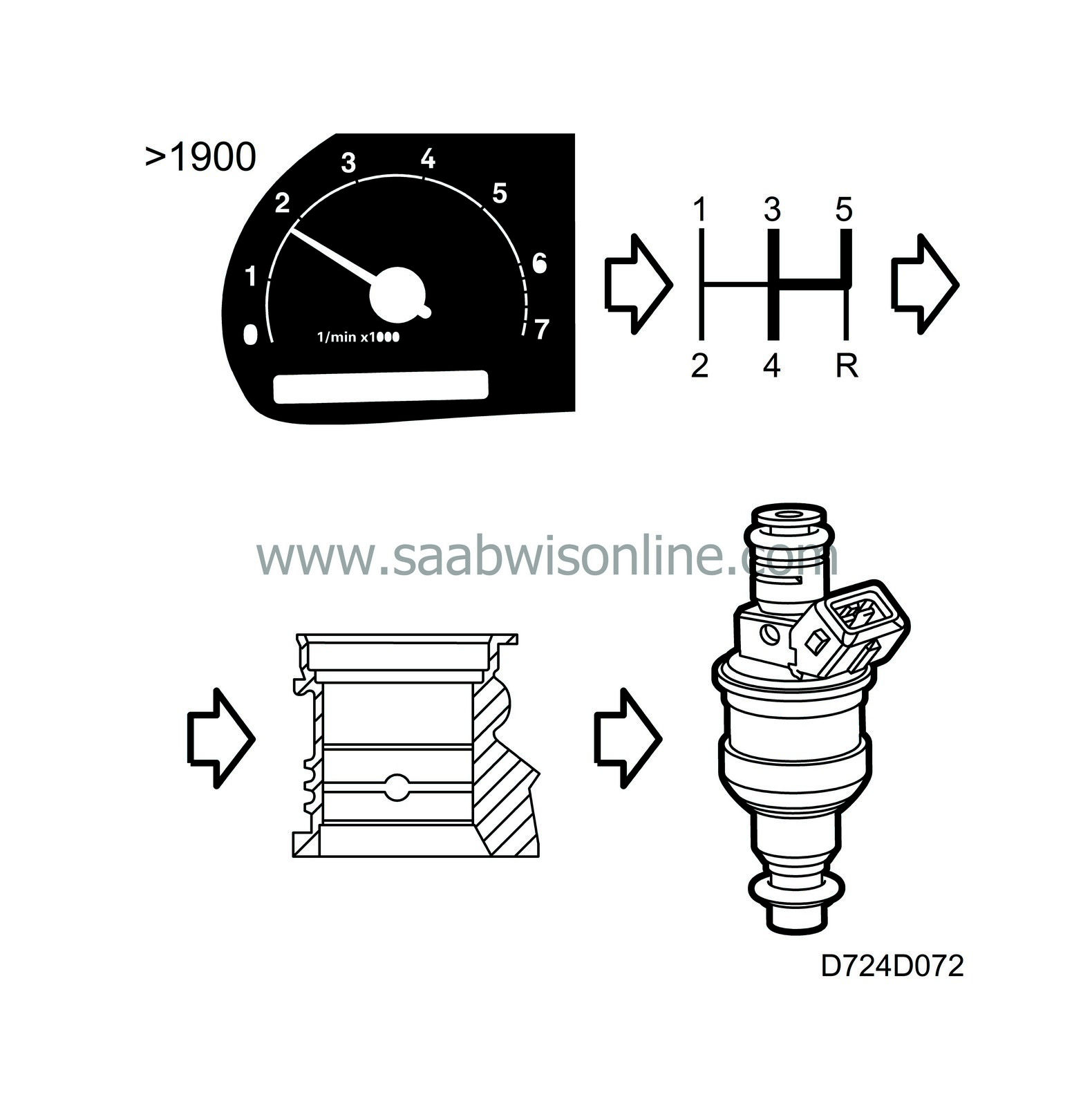
Fuel shut-off will take place after a certain delay (a few seconds) when the throttle is fully closed and engine speed is above 1900 rpm in gears 3, 4 and 5.Fuel shut-off will take place in all gears on cars with automatic transmission.
The injectors are reactivated when the engine speed drops below 1400 rpm.
Fuel consumption
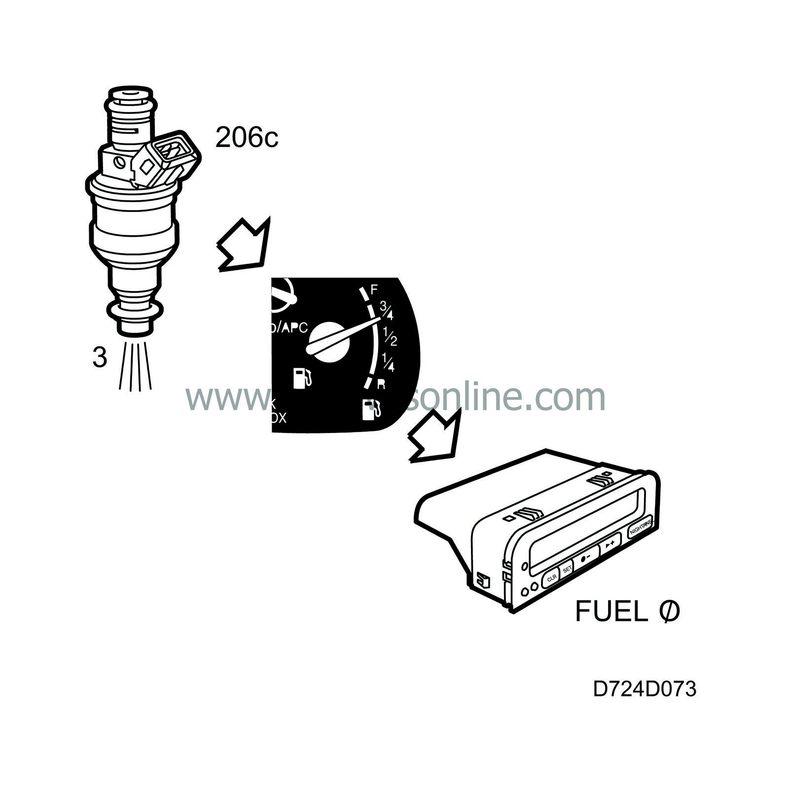
The lead from the control module to injector 3 is also connected to the main instrument unit. The main instrument unit calculates the fuel consumption based on the length of the injection pulses. Fuel consumption is used to provide accurate indication of the fuel level in the tank and to calculate the average fuel consumption in SID.