Instrument and display lighting
|
|
Instrument and display lighting
|
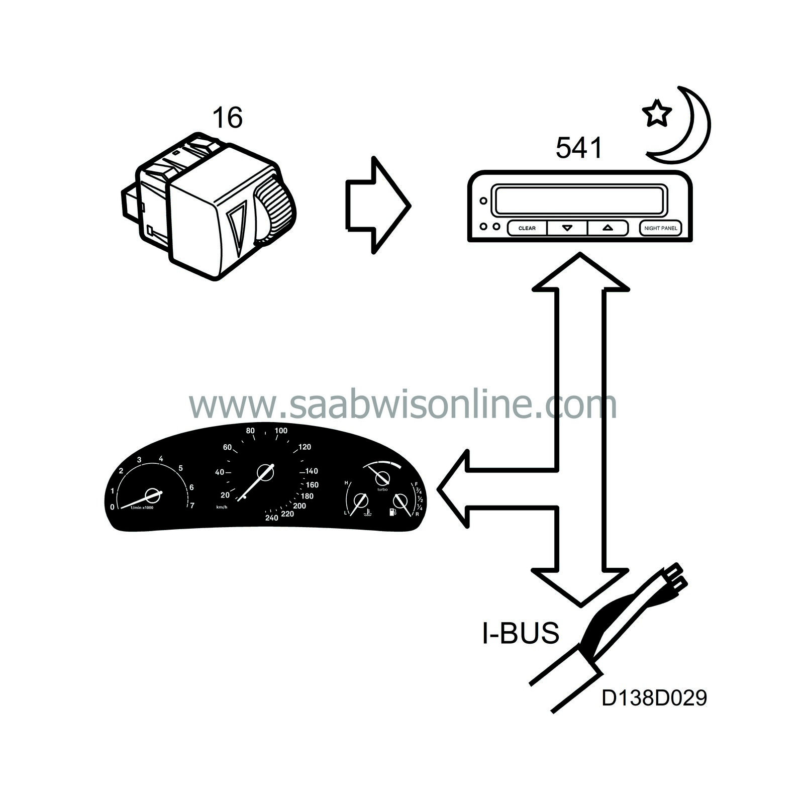
So that the main instrument unit gauges, lamps and displays will be easy to read in both daylight and at night, as well as to achieve optimum bulb life, the main instrument unit's control module regulates the lighting intensity of the display according to the light intensity in the cabin and the rheostat setting selected by the driver.
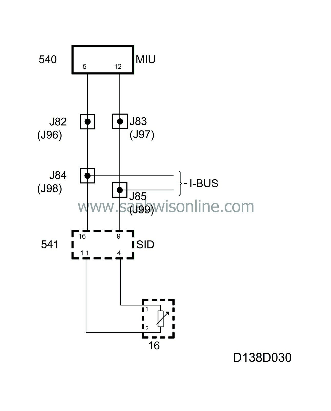
The rheostat is connected to the SID unit, on which the light sensor is also fitted.
The SID unit continuously sends out information on the bus about the following light values:
|
•
|
Rheostat value, unit %.
|
|
•
|
Rheostat value, Night panel (this value is not used by the main instrument unit).
|
|
•
|
Light intensity in the cabin, unit Lux.
|
|
•
|
Display lighting, unit %.
|
The main instrument unit uses the rheostat value to control the following instrument lighting:
|
•
|
Coolant temperature gauge
|
|
•
|
Selector lever indicator (automatic transmission)
|
With the main lighting turned off and fuse 15 for the daylight driving lights removed, the SID unit sends out Rheostat value 0% on the bus.
Diagnostics
The function has its own diagnostics in the sending system.
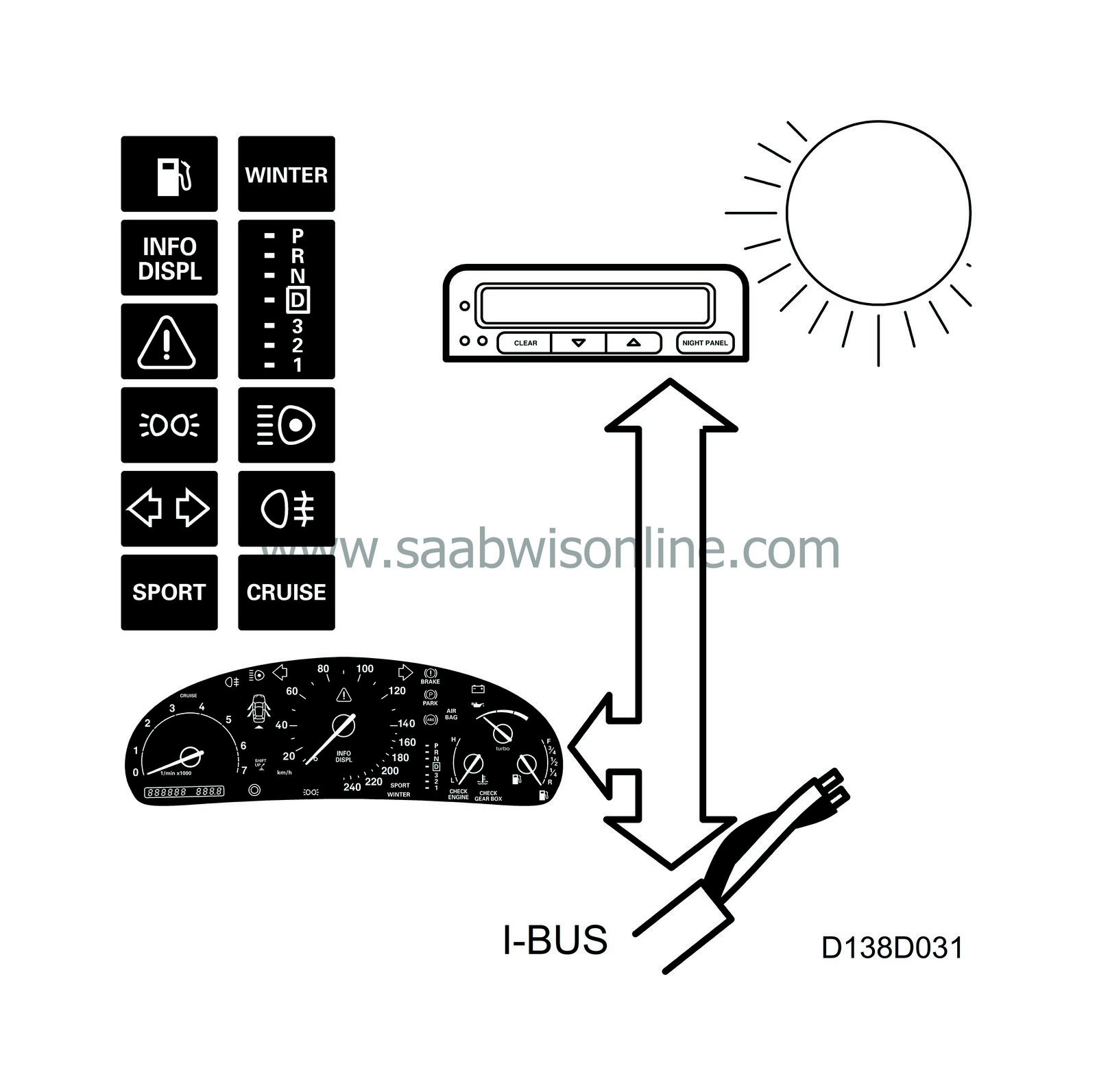
When the light intensity in the cabin exceeds a certain level, the SID unit sends out Rheostat value 0% on the bus.
To increase bulb life, the main instrument unit's control module then turns off the following instrument lighting:
|
•
|
Coolant temperature gauge
|
|
•
|
Selector lever indicator (automatic transmission)
|
For better visibility, the brightness of the indicator and warning lamps is set to two different levels. Low brightness at night and high brightness during the day.
The SID unit sends information on cabin light intensity, unit Lux, to the bus and at a predetermined level the main instrument unit's control module changes the brightness of the following lamps.
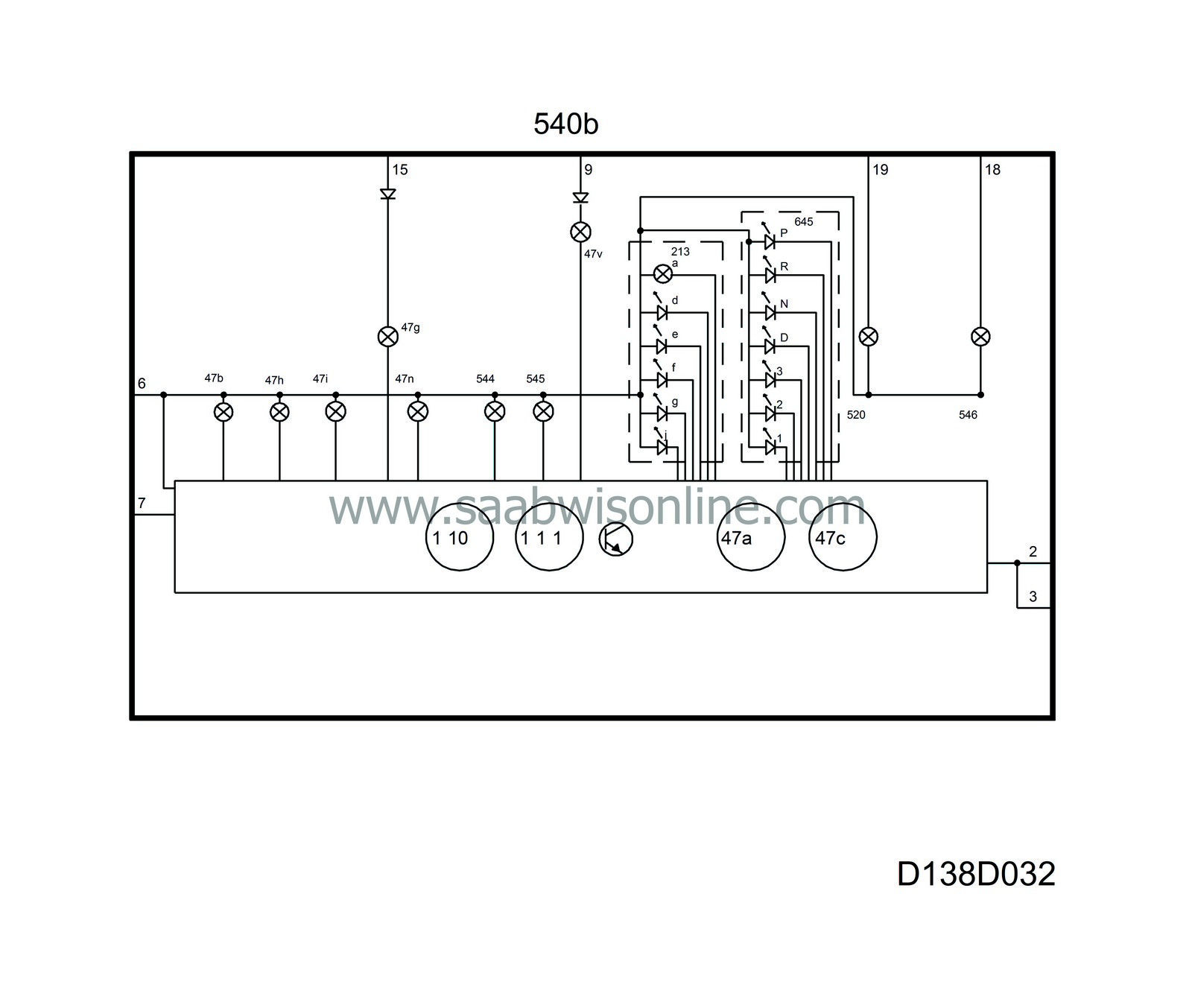
Common to all these lamps is that they are supplied with current (+15 circuit) from the main instrument unit and grounded through its control module.
|
•
|
Fuel reserve indicator lamp
|
|
•
|
LH direction indicators
|
|
•
|
RH direction indicators
|
|
•
|
Selector lever indicator (segment)
|
The following lamps are supplied with current from the component concerned and grounded via the main instrument unit. The brightness of the lamps changes in the same way as the other warning and indicator lamps.
The following lamps are supplied with PWM current and grounded in via the TCM control module. The brightness of the lamps changes in the same way as the other warning and indicator lamps.
Diagnostics
The function has no diagnostics.
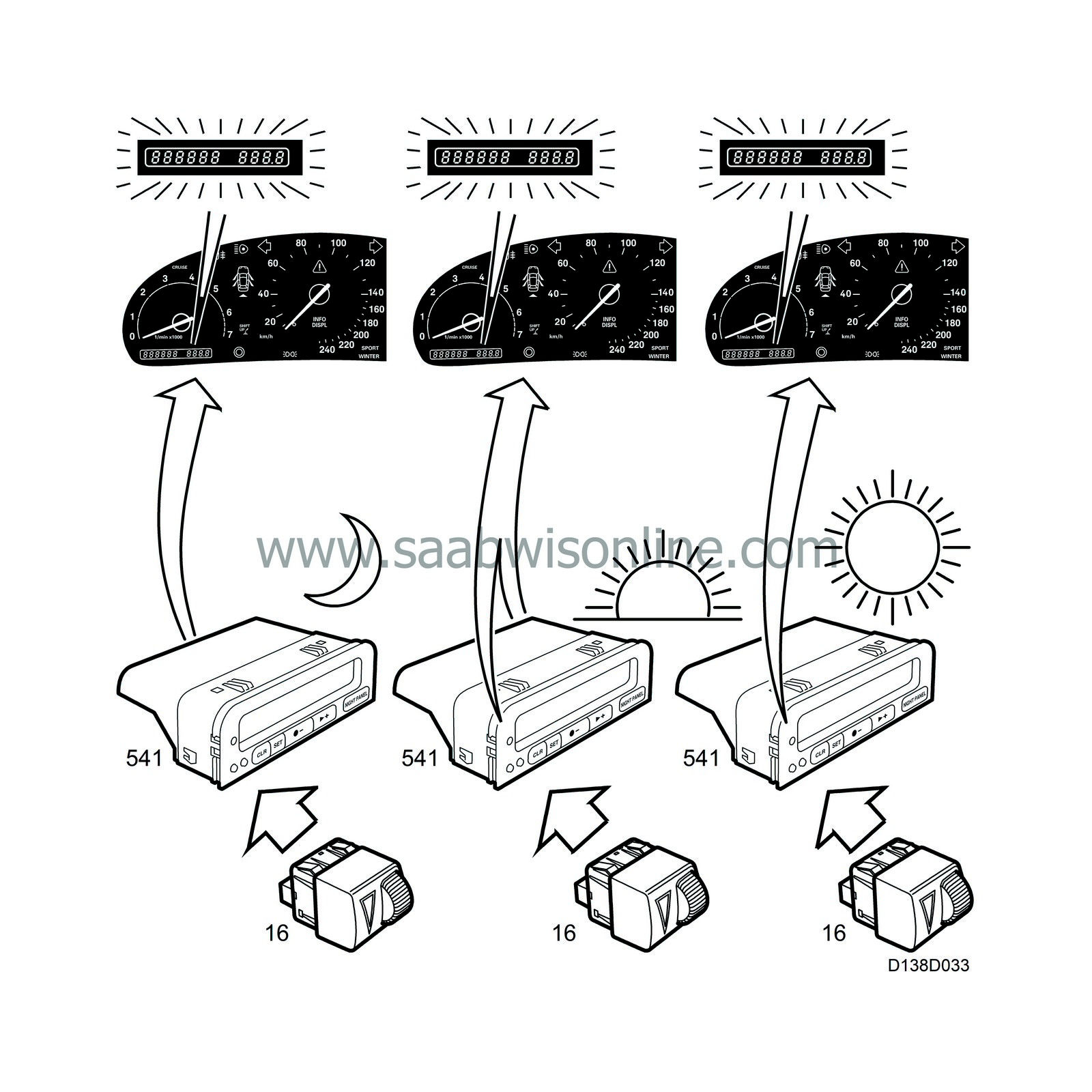
The SID unit calculates a suitable value for the odometer display lighting based on the rheostat value and the value of the light intensity in the cabin, which is obtained from the light sensor.
When it is dark, the lighting is controlled by the rheostat value and when the light in the cabin increases it is controlled by the value of the light intensity in the cabin. This ensures that the odometer display will be easy to read in all lighting conditions.
SID sends the calculated value to the bus as a Display lighting value, unit %.
The main instrument unit control module uses the value to control the odometer display lighting.
Diagnostics
The function has its own diagnostics in the sending system.


