Warning and indicator lamps
| Warning and indicator lamps |
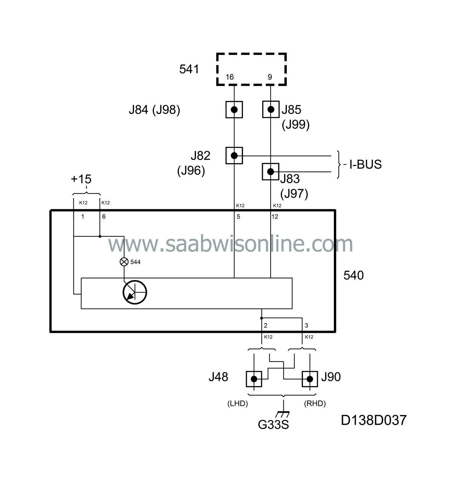
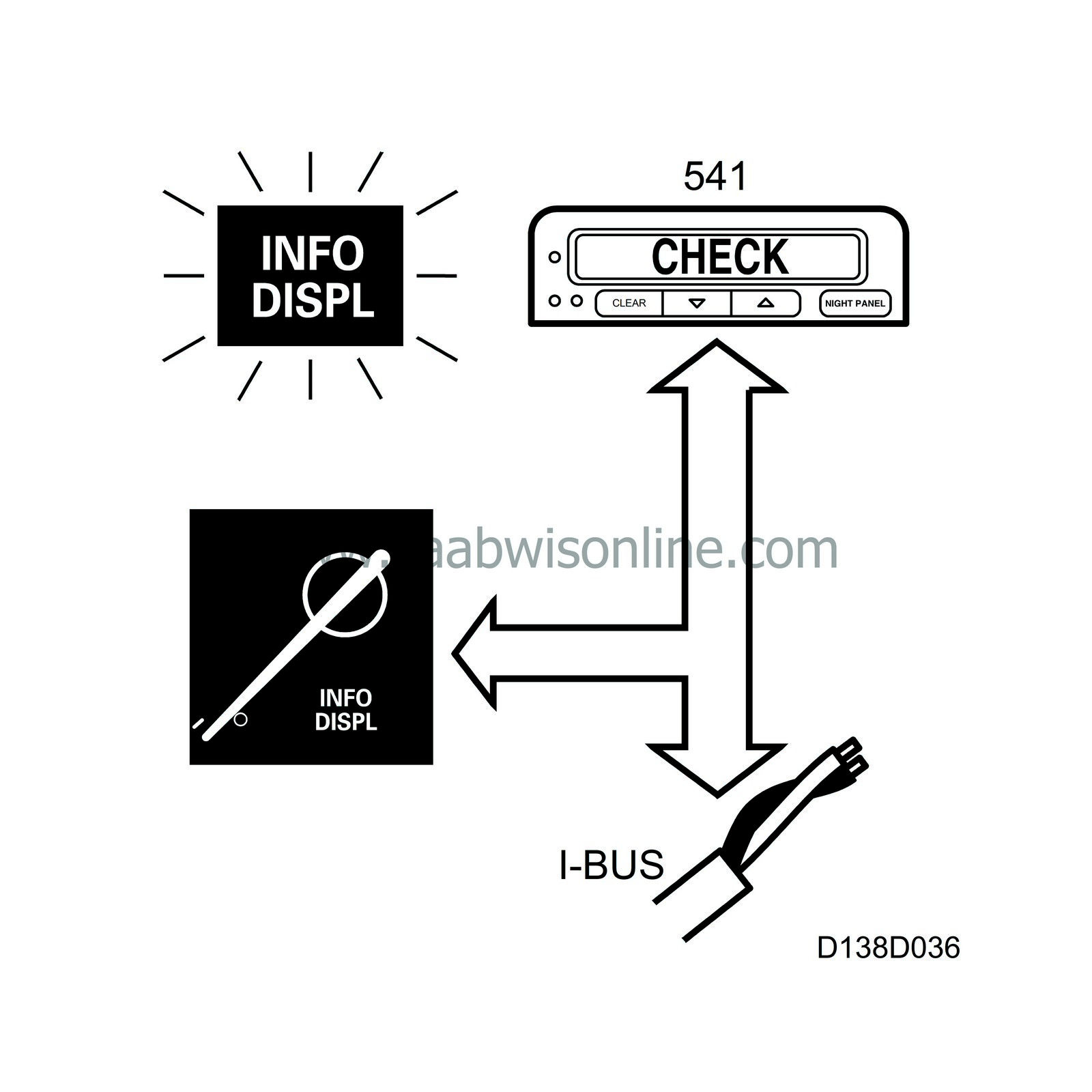
The INFO DISPL lamp lights up when a message is displayed on the SID unit. The lamp is supplied with current (+15 circuit) from the main instrument unit and grounded by the MIU's control module. The SID unit continuously sends bus information INFO DISPL, unit ON/OFF.
On receiving INFO DISPL ON, the control module grounds the output for the lamp which then lights up.
The main instrument unit lights this lamp for 3 seconds when the ignition is switched on.
Diagnostics
The function has no diagnostics.| Central warning lamp |
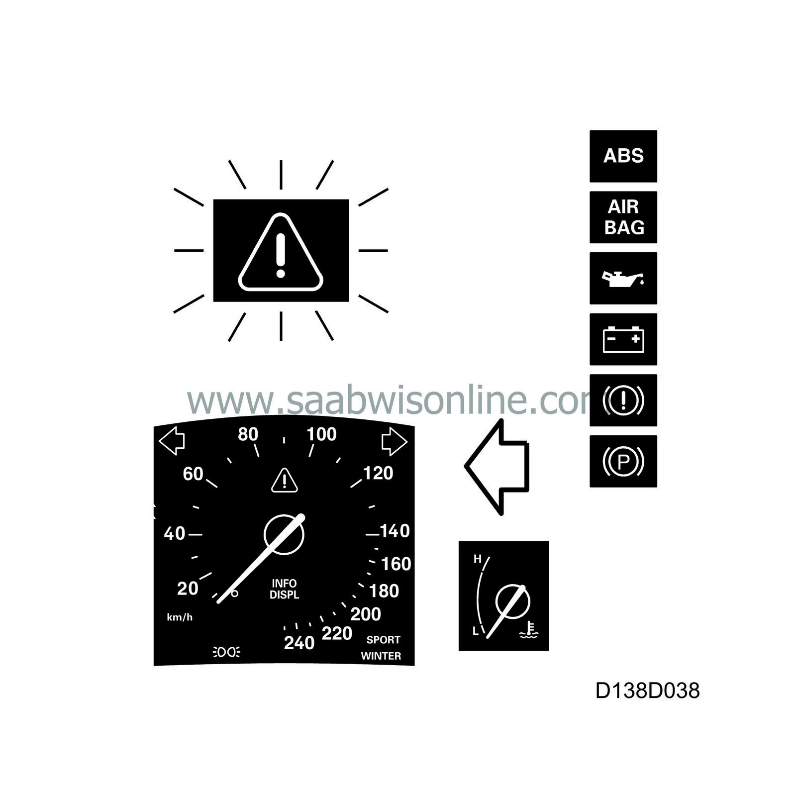
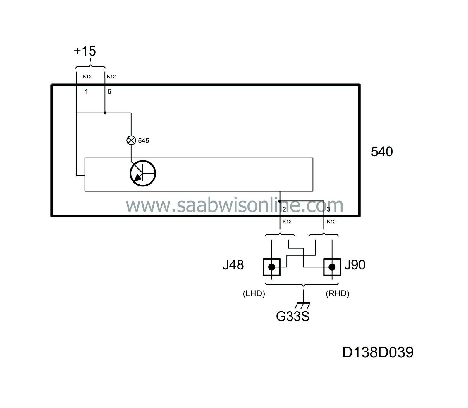
The central warning lamp lights up when a fault occurs in a system having to do with the car's safety.
The lamp is supplied with current (+15 circuit) from the main instrument unit and grounded by the MIU's control module when one of the following warning or indicator lamps lights up:
| • |
Warning lamp, AIRBAG
|
|
| • |
Engine oil pressure warning lamp
|
|
| • |
Warning lamp, charging
|
|
| • |
Warning lamp, brake fluid level
|
|
| • |
Warning lamp, handbrake
|
|
| • |
ABS warning lamp
|
|
The handbrake lamp lights the central warning lamp if the speed passes 5 km/h from a speed below 5 km/h.
Common to the above lamps is that they are supplied with current (+15 circuit) in the main instrument unit and grounded through the relevant component/system.
The central warning lamp also lights up when:
| • |
Coolant temperature exceeds 129°C
|
|
At the same time as the central warning lamp lights up, the main instrument unit sends bus information to the SID unit requesting it to sound a signal. This does not occur when the ignition is switched on as the lamps are then only tested. An engine speed of above 310 rpm is required for this request.
Diagnostics
The function has no diagnostics.| Engine oil pressure warning lamp |
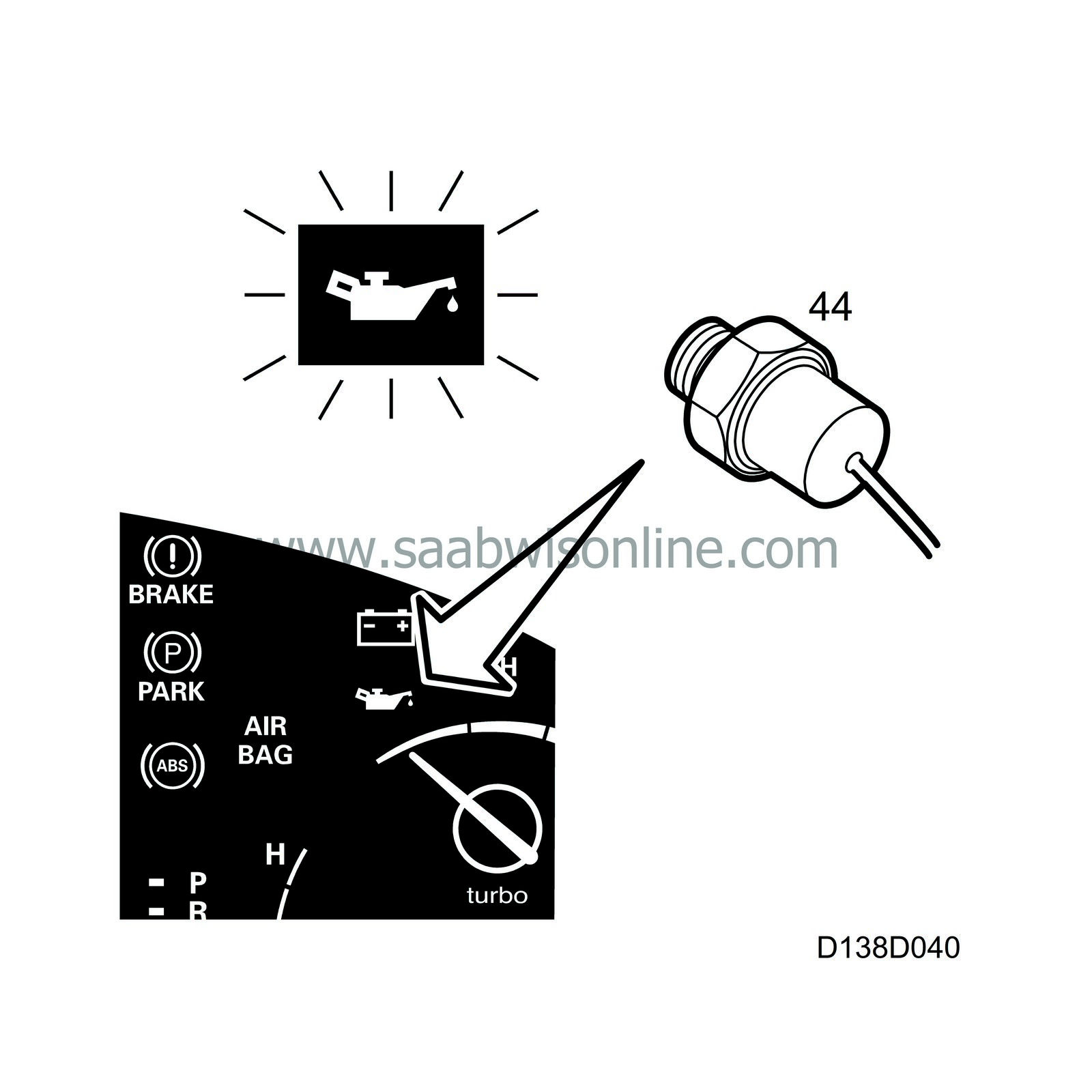
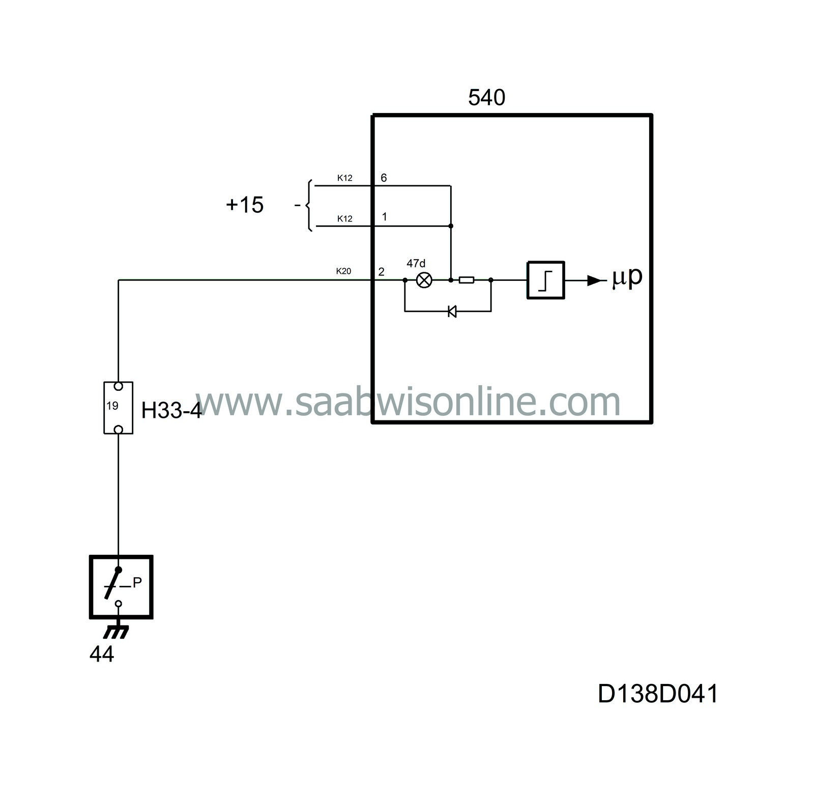
The oil pressure warning lamp is located in the top right-hand corner. It warns the driver when engine oil pressure is too low.
The lamp is supplied with current in the main instrument unit and grounded via terminal 2 (K20) of the oil pressure sensor.
If the oil pressure is below 0.3-0.5 bar, the oil pressure sensor contacts close, the circuit is grounded and the lamp lights up. At the same time the central warning lamp lights up and, at engine speeds above 310 rpm, the MIU sends a request to the SID unit for activation of an acoustic signal.
Diagnostics
The function has no diagnostics.| Warning lamp, charging |
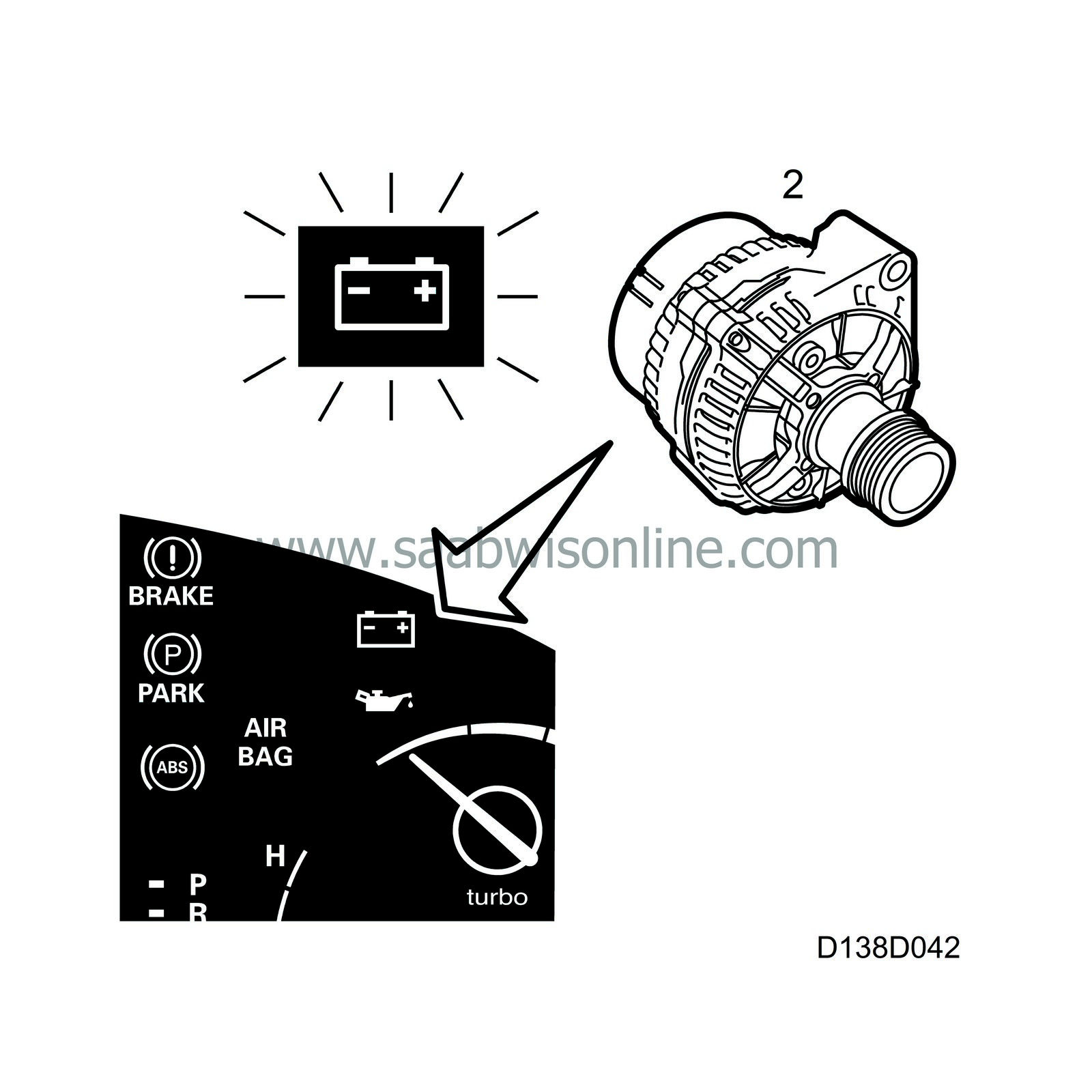
The charging warning lamp is located in the top right-hand corner and informs the driver whether the generator is charging or not.
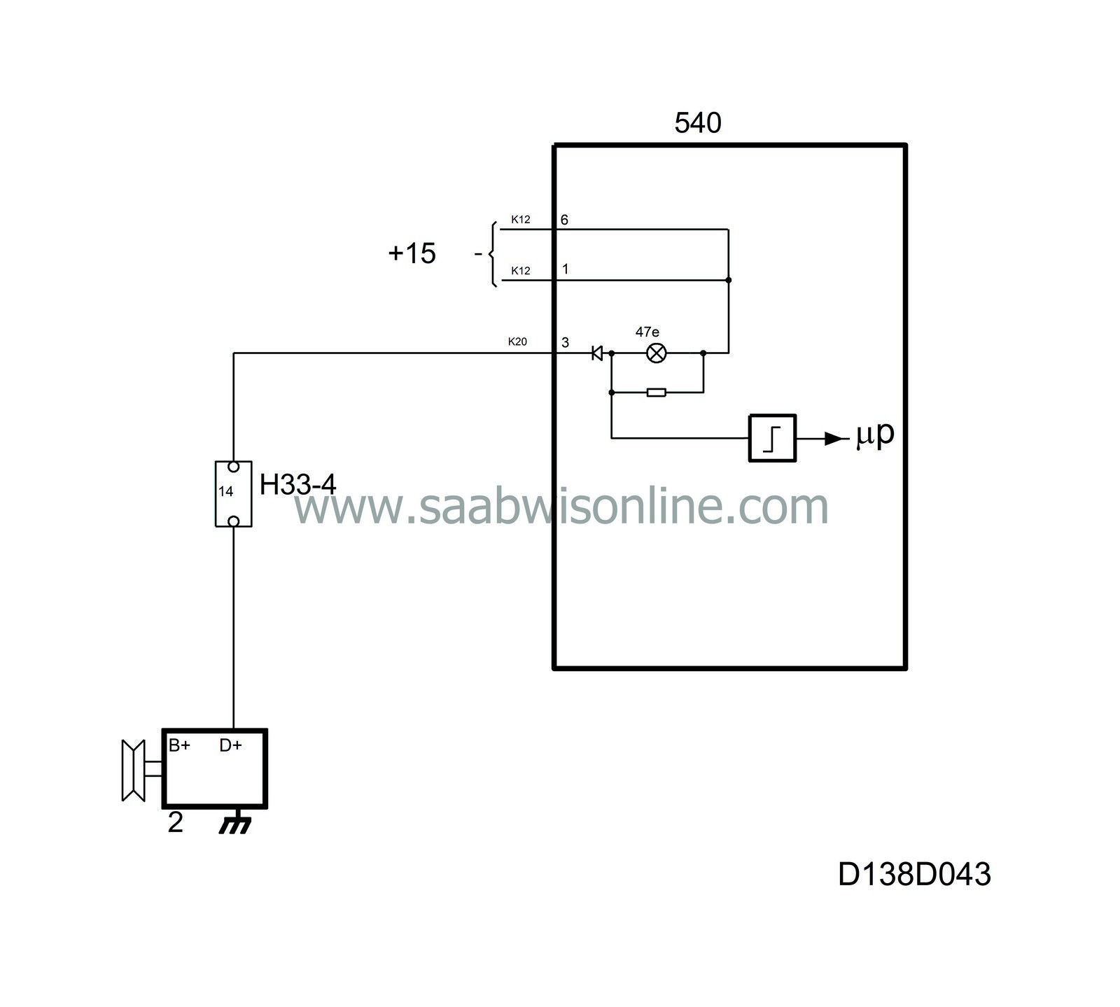
The lamp is supplied with current in the main instrument unit and grounded by the generator via terminal 3 (K20).
If the generator does not rotate or charge for any reason, the indicator lamp circuit is grounded via the regulator through the generator's field winding, causing the lamp to light up. At the same time the central warning lamp lights up and, at engine speeds above 310 rpm, the MIU sends a request to the SID unit for activation of an acoustic signal.
When the generator is charging, its D+ and B+ terminals will have the same voltage. Both terminals of the warning lamp will then be supplied with this same voltage and the lamp goes out.
A resistor is connected in parallel with the lamp. This resistor ensures that magnetizing current is supplied to the generator on starting even if the lamp is faulty.
A diode is connected in series with the resistor/lamp. This diode prevents the lamp from glowing at high charging voltages.
Diagnostics
The function has no diagnostics.| Warning lamp, AIRBAG |
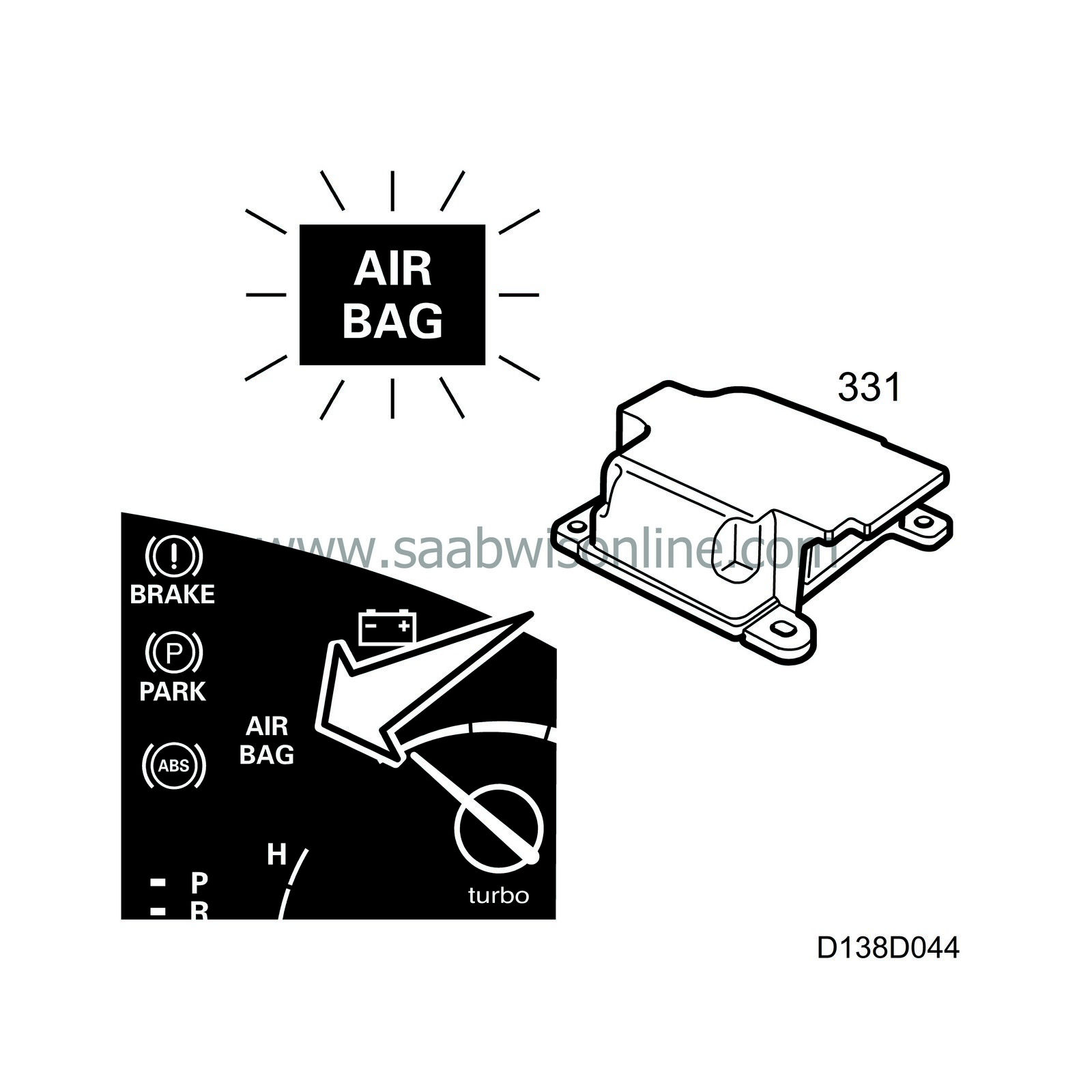
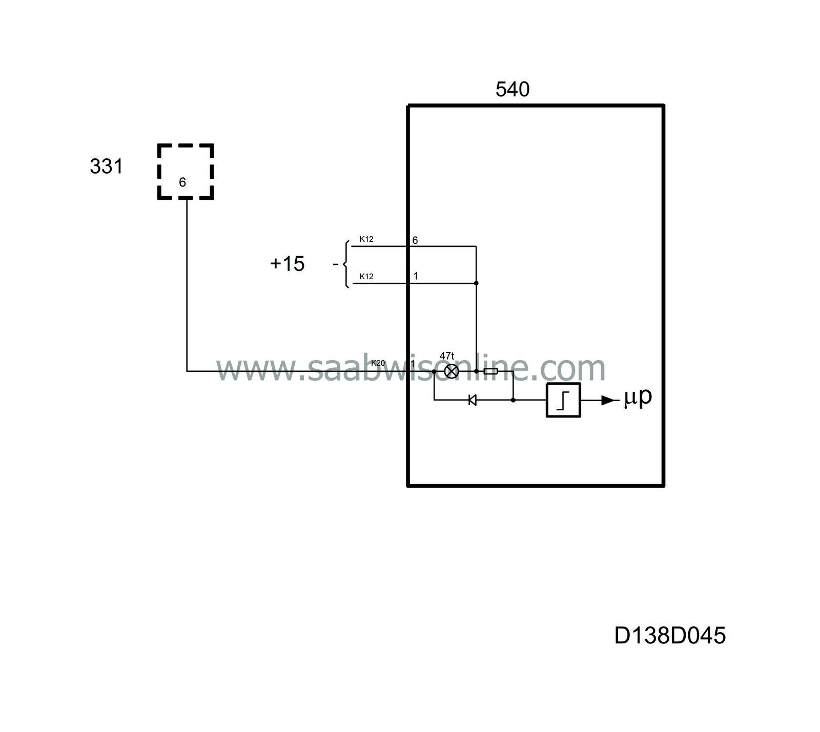
The AIRBAG warning lamp is located in the right-hand part of the main instrument unit. This lamp informs the driver when a fault occurs in the Airbag system. The central warning lamp serves as a second airbag warning lamp and does not go out until all its warning inputs are normal.
The AIRBAG warning lamp is supplied with current (+15 circuit) in the main instrument unit via pin 1 (K20) of the Airbag control module.
Should a fault arise in the system, the AIRBAG Warning lamp and central warning lamp light up continuously and at engine speeds above 310 rpm the MIU sends a request to the SID unit for activation of an acoustic signal.
If the Airbag system has been activated – sent detonating current to the explosive charges in the gas generators – the AIRBAG Warning lamp and central warning lamp will light up and stay on.
The airbag control module lights the lamp when the ignition is turned on. If there are no faults, the lamp will go out after about 3 seconds.
Diagnostics
An open circuit/short circuit sets a diagnostic trouble code in the Airbag control module.| Warning lamp, brake fluid level |
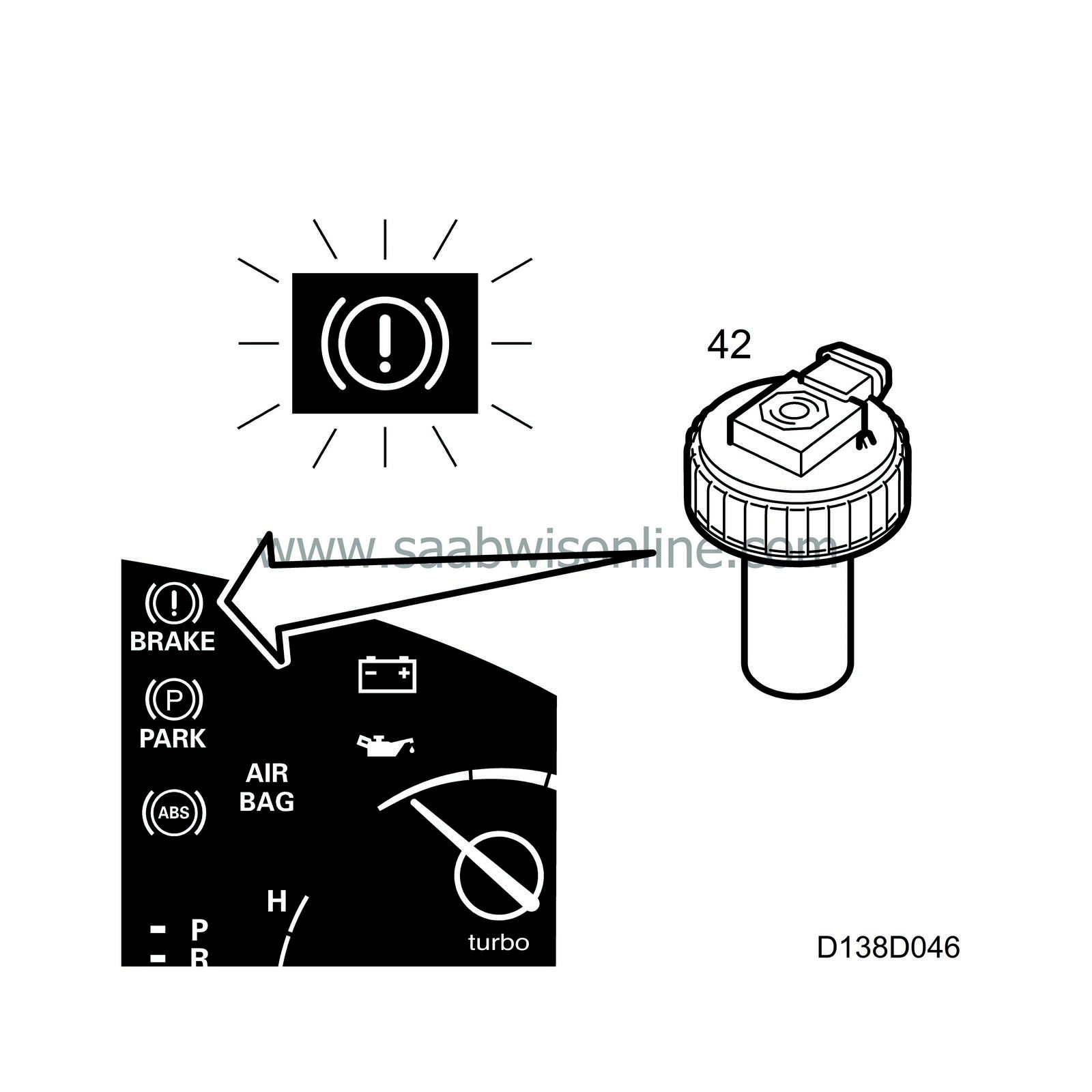
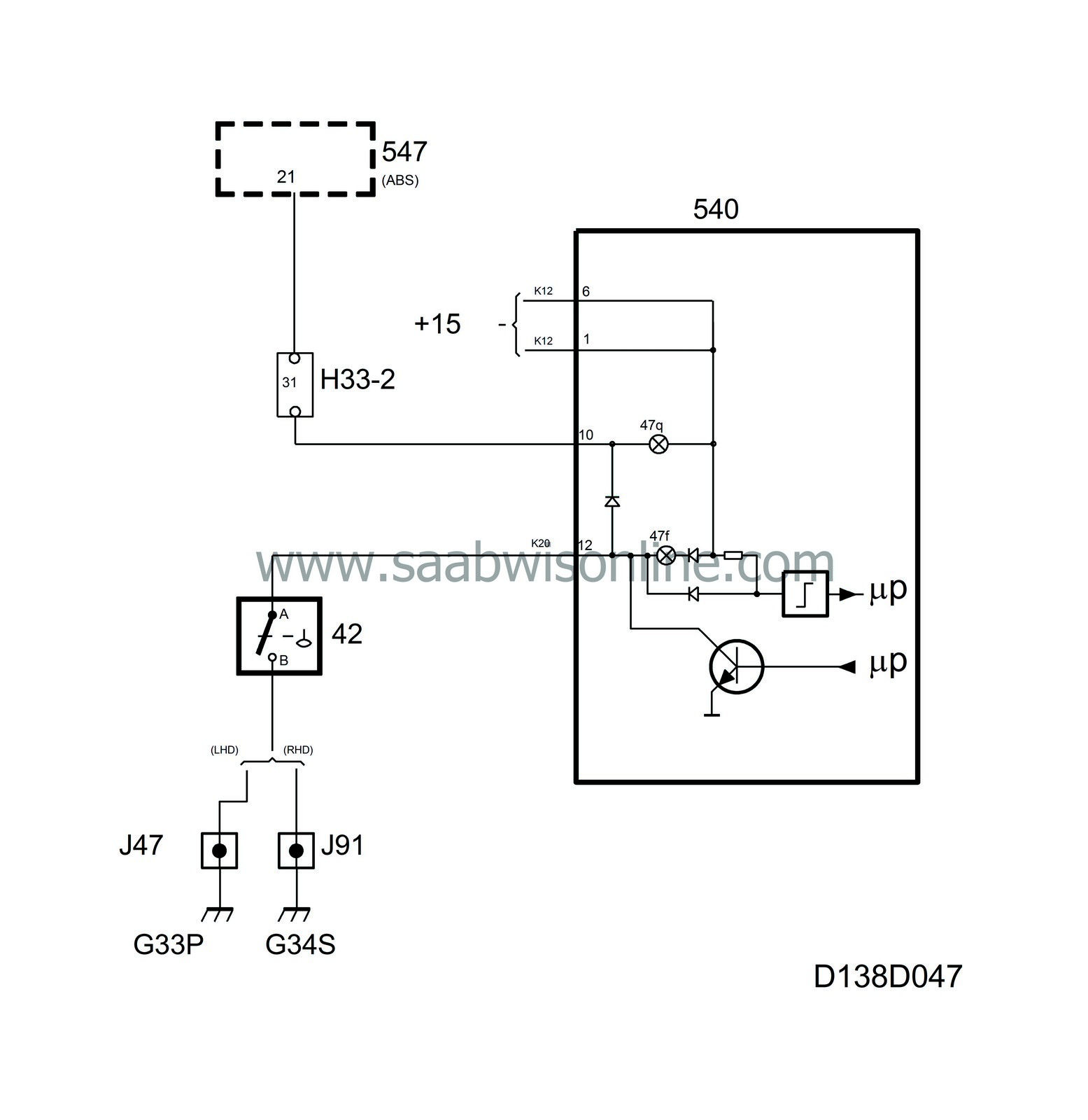
The brake fluid level warning lamp is located in the right-hand part of the main instrument unit. It warns the driver if the level in the brake fluid reservoir is too low. It also comes on if a fault develops in the anti-lock brake system (ABS).
The lamp is supplied with current in the main instrument unit and grounded via terminal 12 (K20) of the brake fluid reservoir.
If the level is too low, the central warning lamp also lights up and, at engine speeds above 310 rpm, the MIU sends a request to the SID unit for activation of an acoustic signal.
The main instrument unit lights the brake fluid level warning lamp for 3 seconds when the ignition is turned on.
Diagnostics
The function has no diagnostics.| Warning lamp, handbrake |
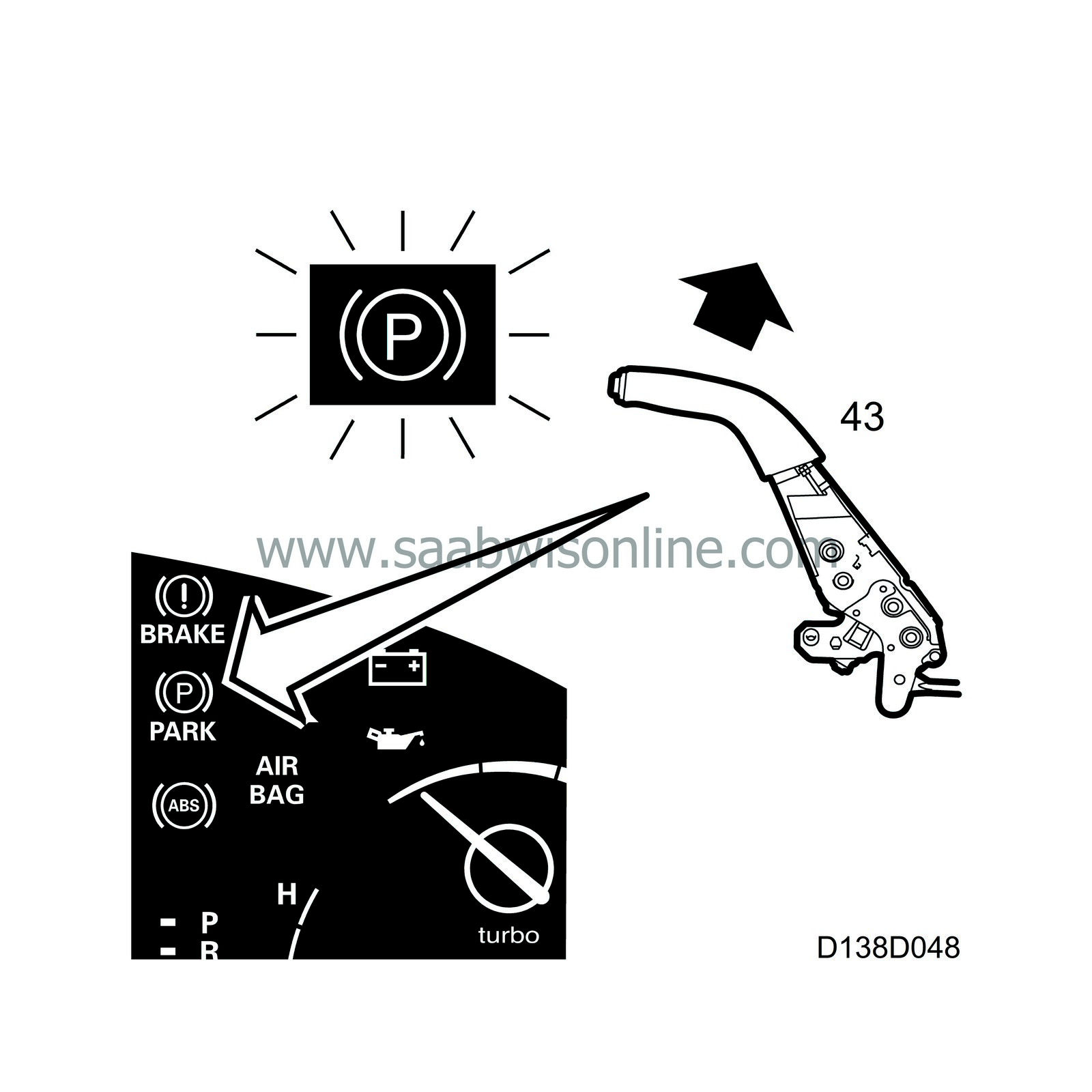
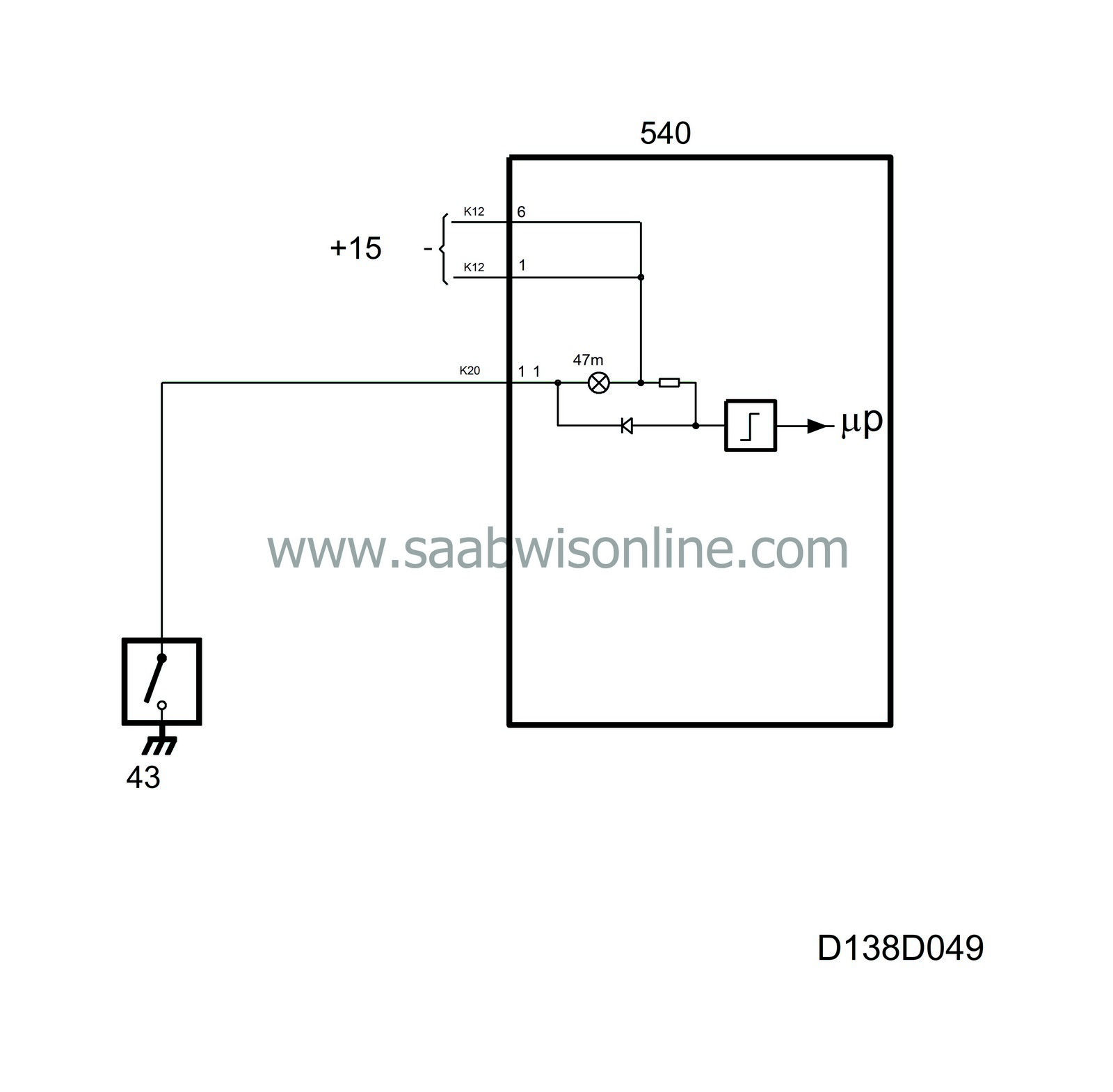
The handbrake warning lamp is located in the right-hand part of the main instrument unit. It comes on to inform the driver that the handbrake is applied.
The lamp is supplied with current in the main instrument unit. As long as the handbrake remains applied, the switch operated by the handbrake lever grounds the lamp via terminal 11 (K20), causing it to light up.
If the vehicle speed passes 5 km/h from a speed below 5 km/h while the handbrake is applied, the central warning lamp will also light up and the MIU will send a request to the SID unit for activation of an acoustic signal.
Diagnostics
The function has no diagnostics.| ABS warning lamp |
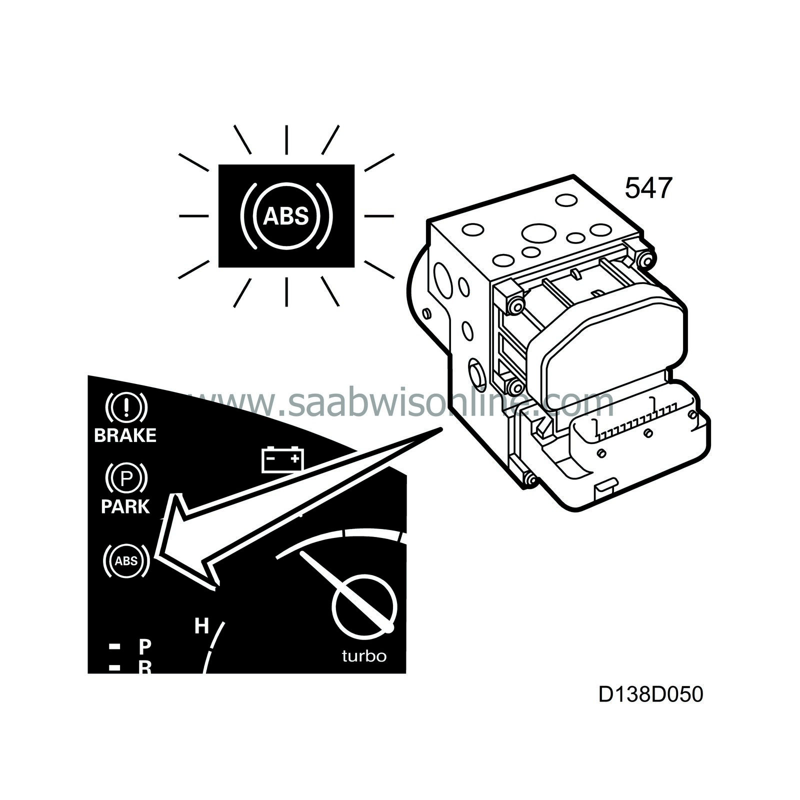
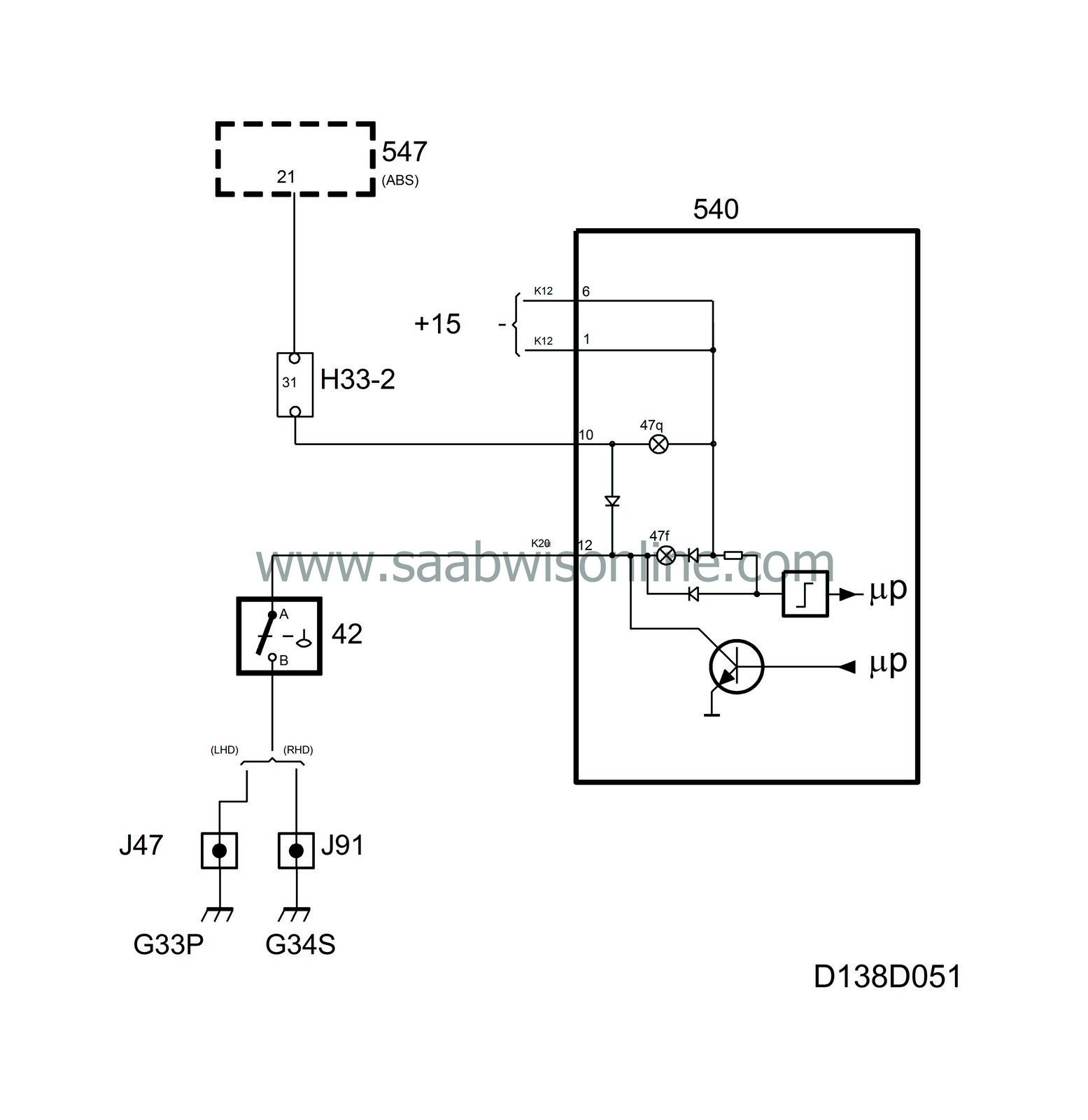
The ABS control module monitors the function of the ABS system and in the event of a fault lights the ABS warning lamp, which is situated on the right-hand side of the main instrument unit.
When the ABS lamp lights up, the anti-lock braking system is disabled and the brakes work just like a conventional braking system.
The lamp is supplied with current in the main instrument unit and grounded via main instrument unit terminal 10 (K20) in the ABS control module.
The ABS control module lights the lamp when the ignition is switched on and if there is no fault it will go out after approx. 3 seconds.
When the ABS warning lamp lights up, the brake fluid warning lamp and central warning lamp will also light up.
Diagnostics
The function has no diagnostics.| SPORT indicator lamp |
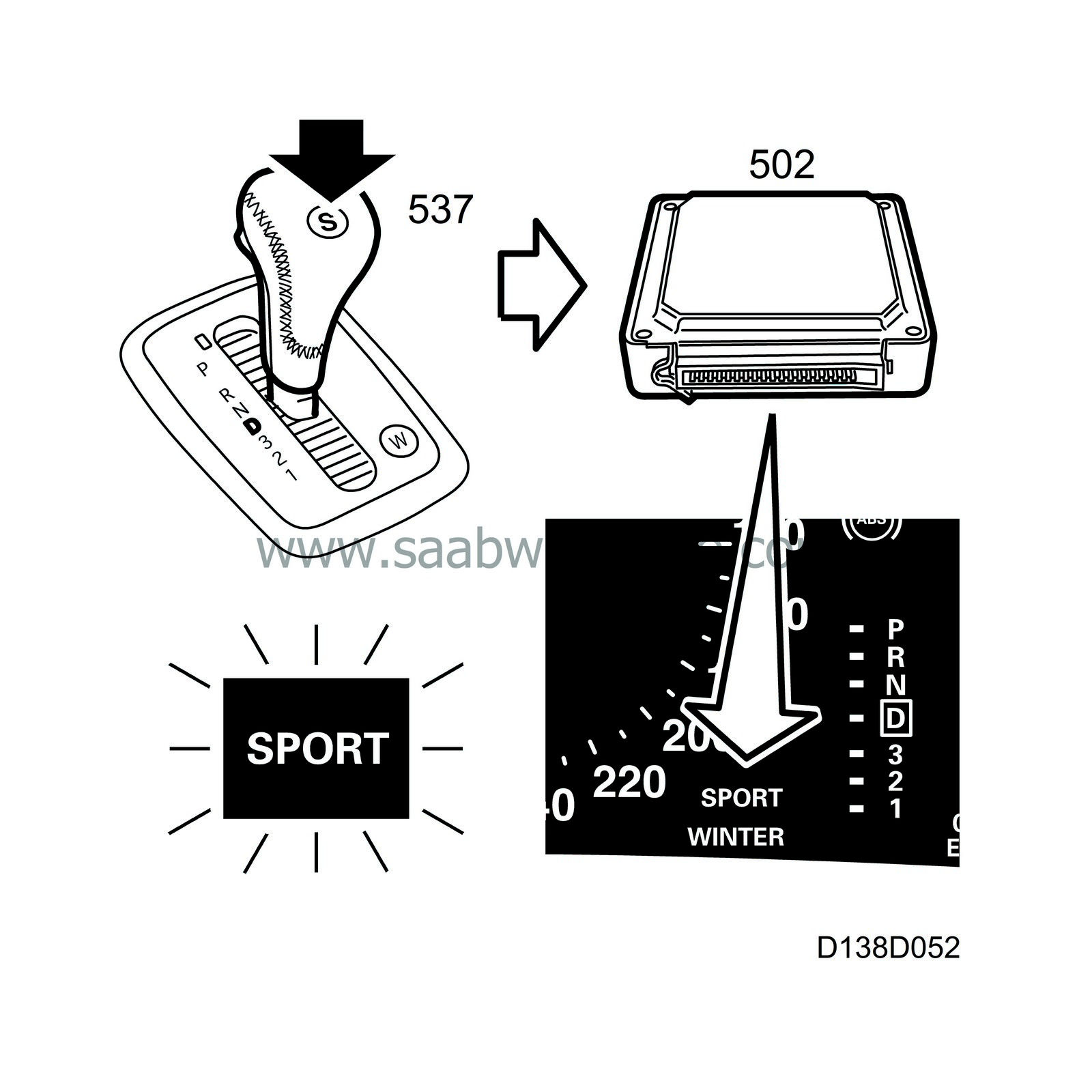
On cars with automatic transmission, the SPORT indicator lamp lights up when the Sport button (S) on the selector lever is pressed.
In SPORT mode, the transmission remains longer in each gear.
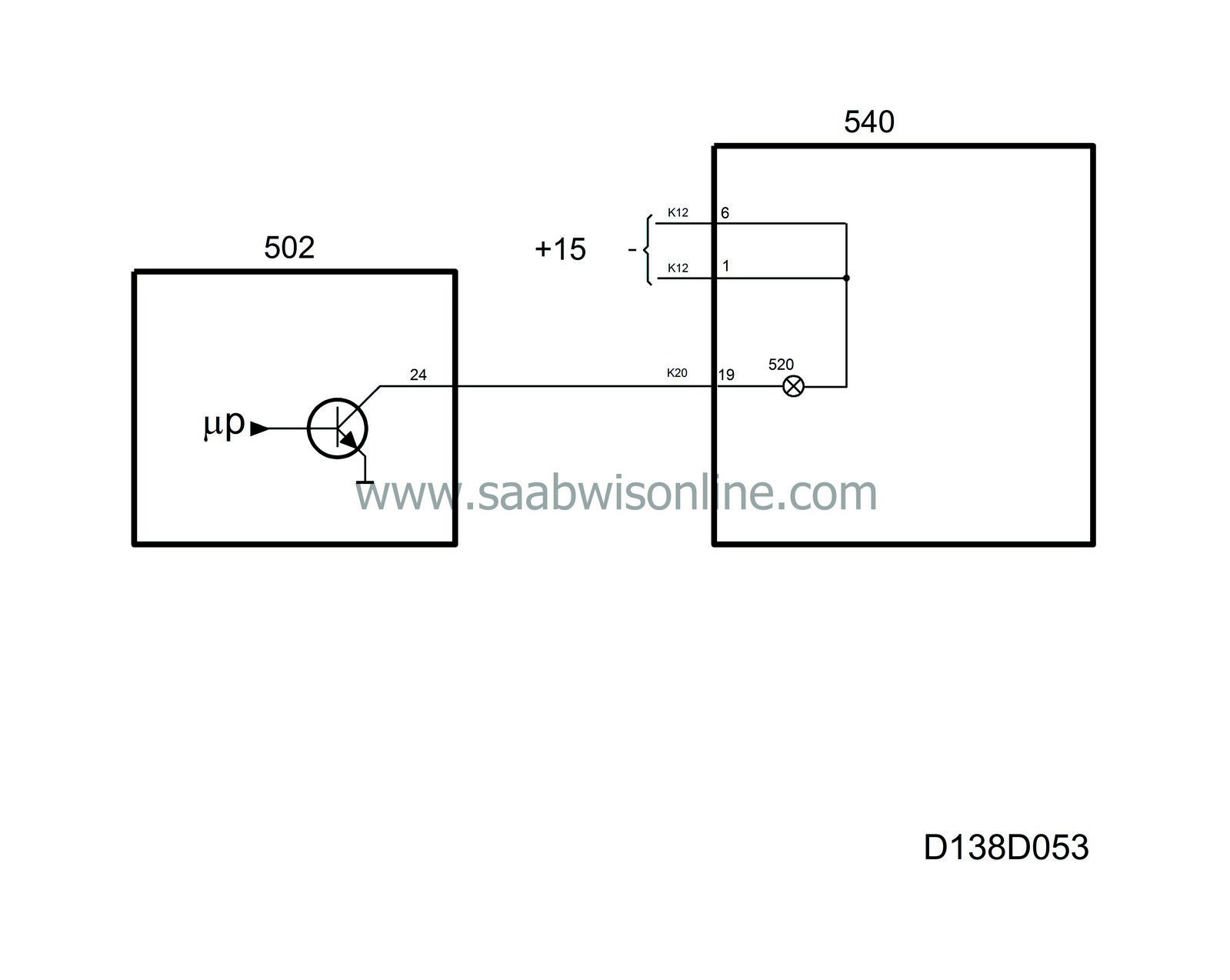
The lamp is supplied with current (+15 circuit) in the main instrument unit via terminal 19 (K20) in the TCM control module.
The indicator lamp goes out under the following conditions:
| • |
When the sport button is depressed again.
|
|
| • |
When the transmission is in Limp-home mode.
|
|
| • |
When Winter mode is selected.
|
|
| • |
If the ignition is turned off and then on again.
|
|
Diagnostics
The function has no diagnostics.| WINTER indicator lamp |
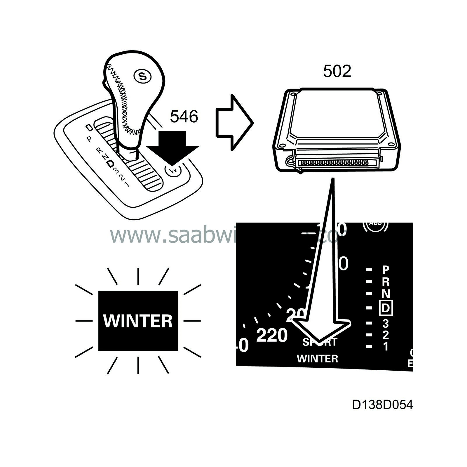
To facilitate moving off on slippery road surfaces, the TCM has a winter mode, i.e. the car starts in 3rd gear when the Winter button (W) beside the selector lever is depressed.
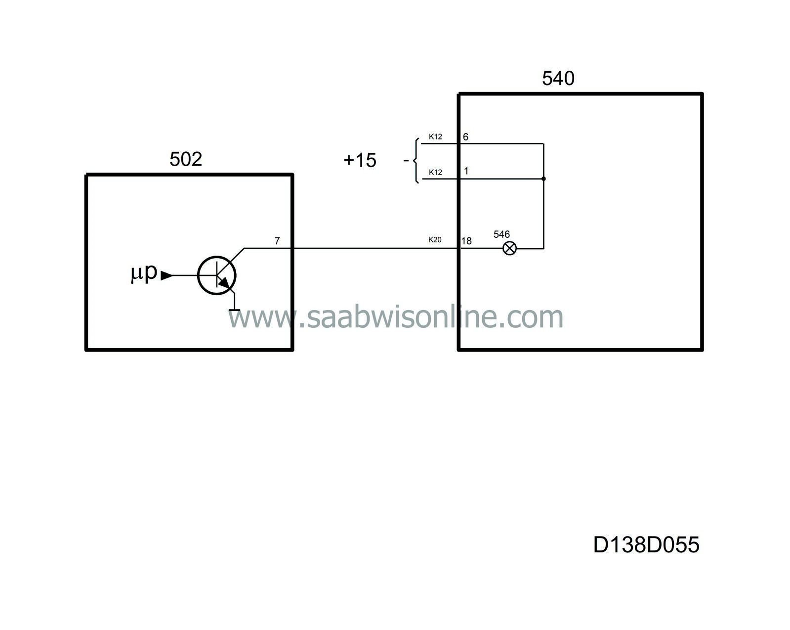
The lamp is supplied with current (+15 circuit) in the main instrument unit and grounded via terminal 18 (K20) in the transmission control module (TCM).
The indicator lamp goes out under the following conditions:
| • |
When the Winter button is pressed again.
|
|
| • |
When the transmission is in Limp-home mode.
|
|
| • |
If the ignition is turned off and then on again.
|
|
| • |
When the transmission fluid temperature is above 140°C.
|
|
Diagnostics
The function has no diagnostics.| CHECK GEARBOX indicator lamp |
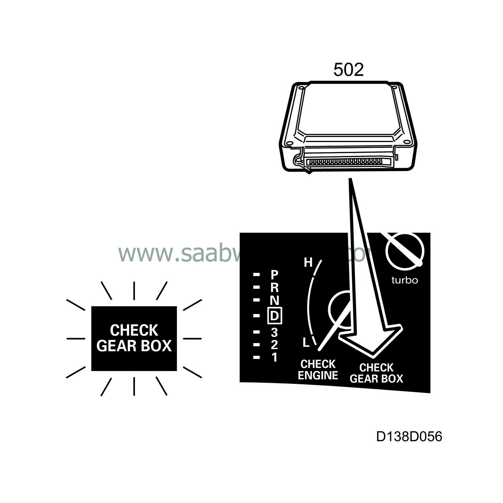
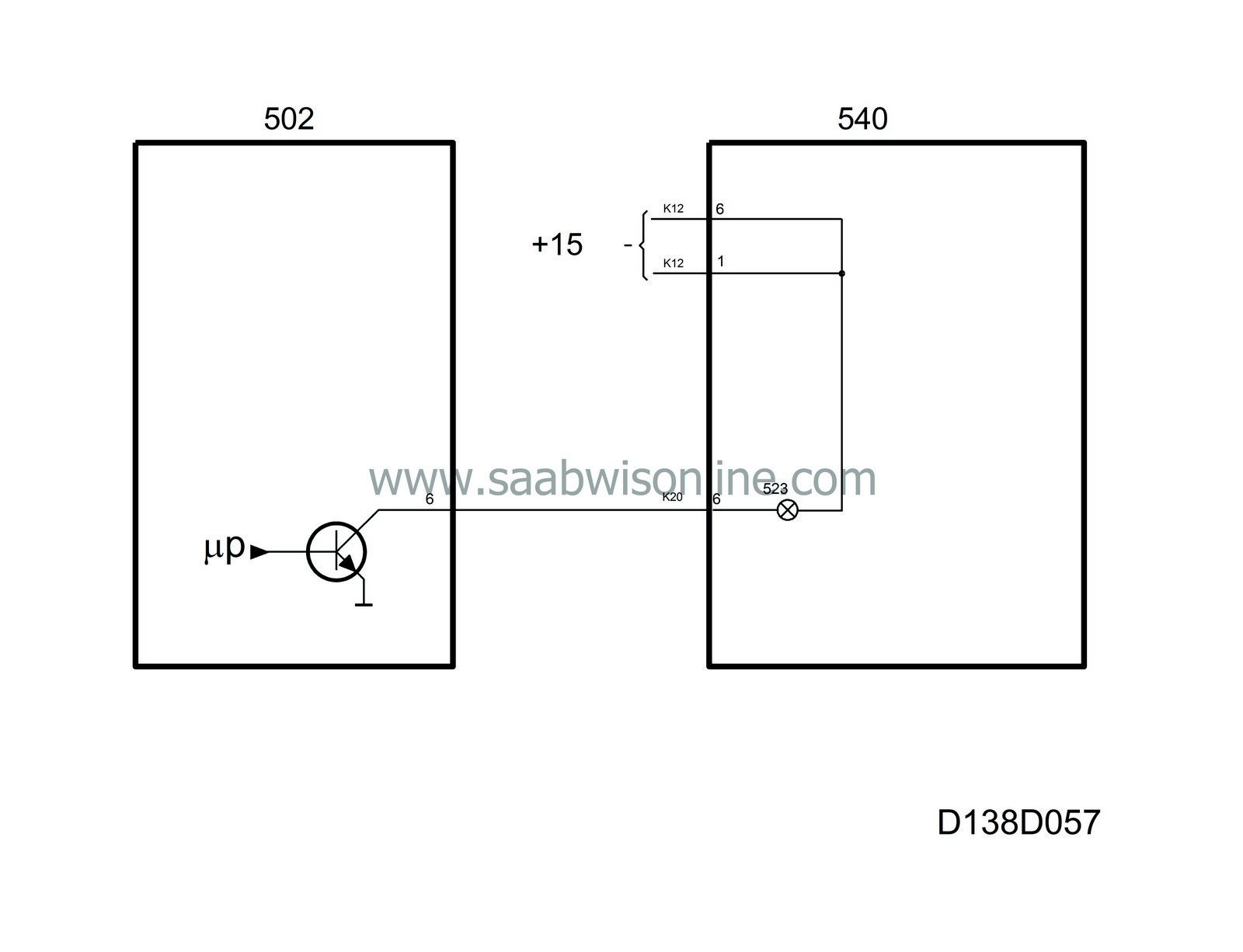
If there is a fault in the automatic transmission or its control module, the TCM lights the CHECK GEARBOX warning lamp in the main instrument unit.
The lamp is supplied with current (+15 circuit) in the main instrument unit and grounded via terminal 6 (K20) in the transmission control module (TCM).
When the ignition is turned on, the TCM lights the lamp for approx. 3 seconds and if there is no fault the lamp will go out.
Diagnostics
The function has its own diagnostics in the sending system.| Fuel reserve indicator lamp |
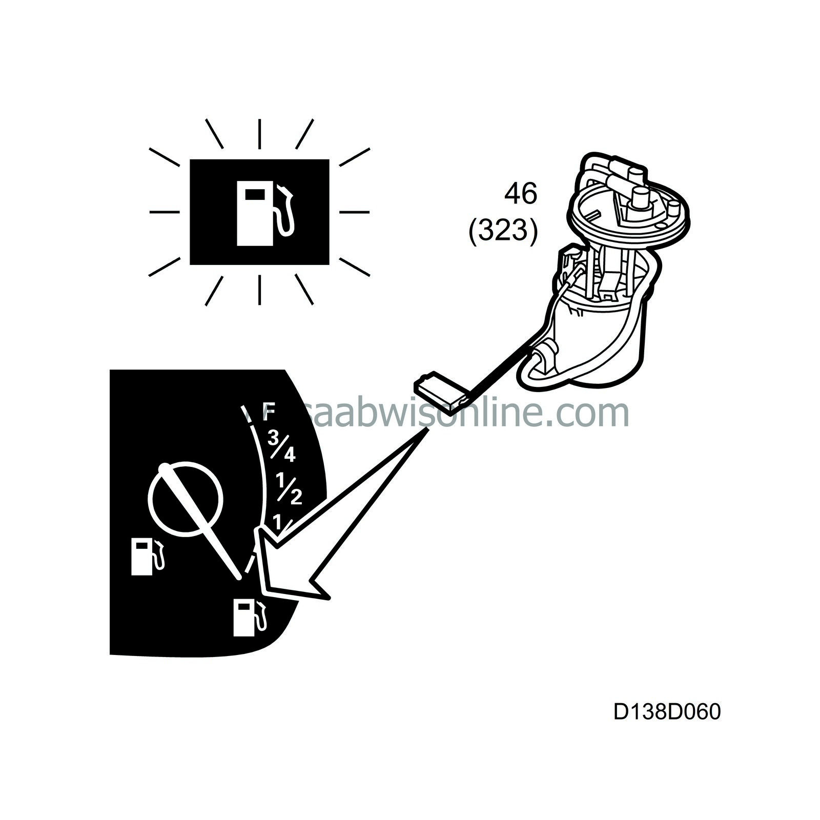
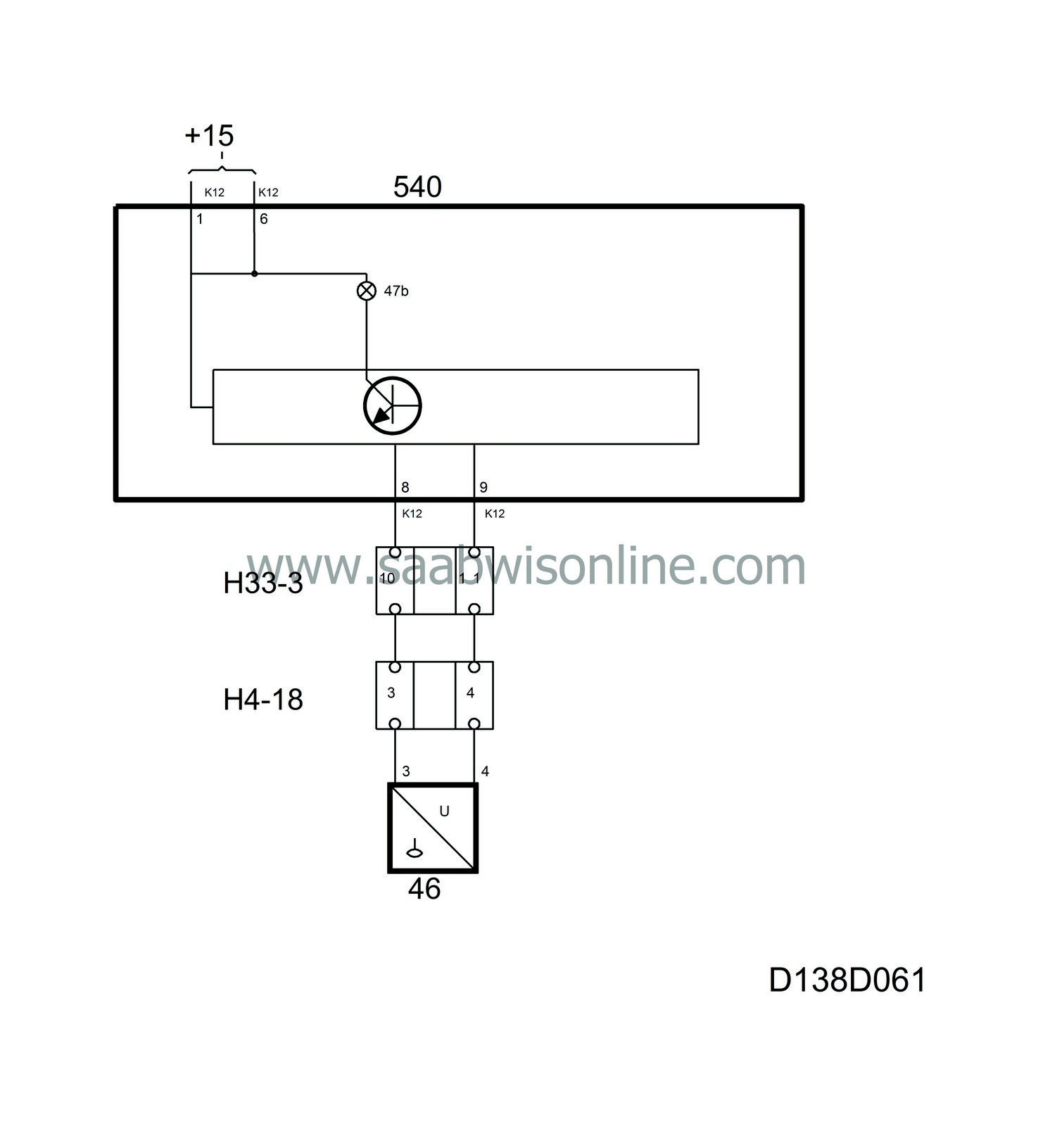
When there is only about 10 litres of fuel remaining in the tank a lamp comes on to indicate low fuel level. The lamp is supplied with current in the main instrument unit and when it should light up it is grounded by the main instrument unit's control module.
The main instrument unit lights the lamp for 3 seconds when the ignition is switched on.
Diagnostics
An open circuit/short circuit sets diagnostic trouble code B1720. The gauge needle indicates 0 litres and the fuel reserve indicator lamp lights up.| CHECK ENGINE indicator lamp |
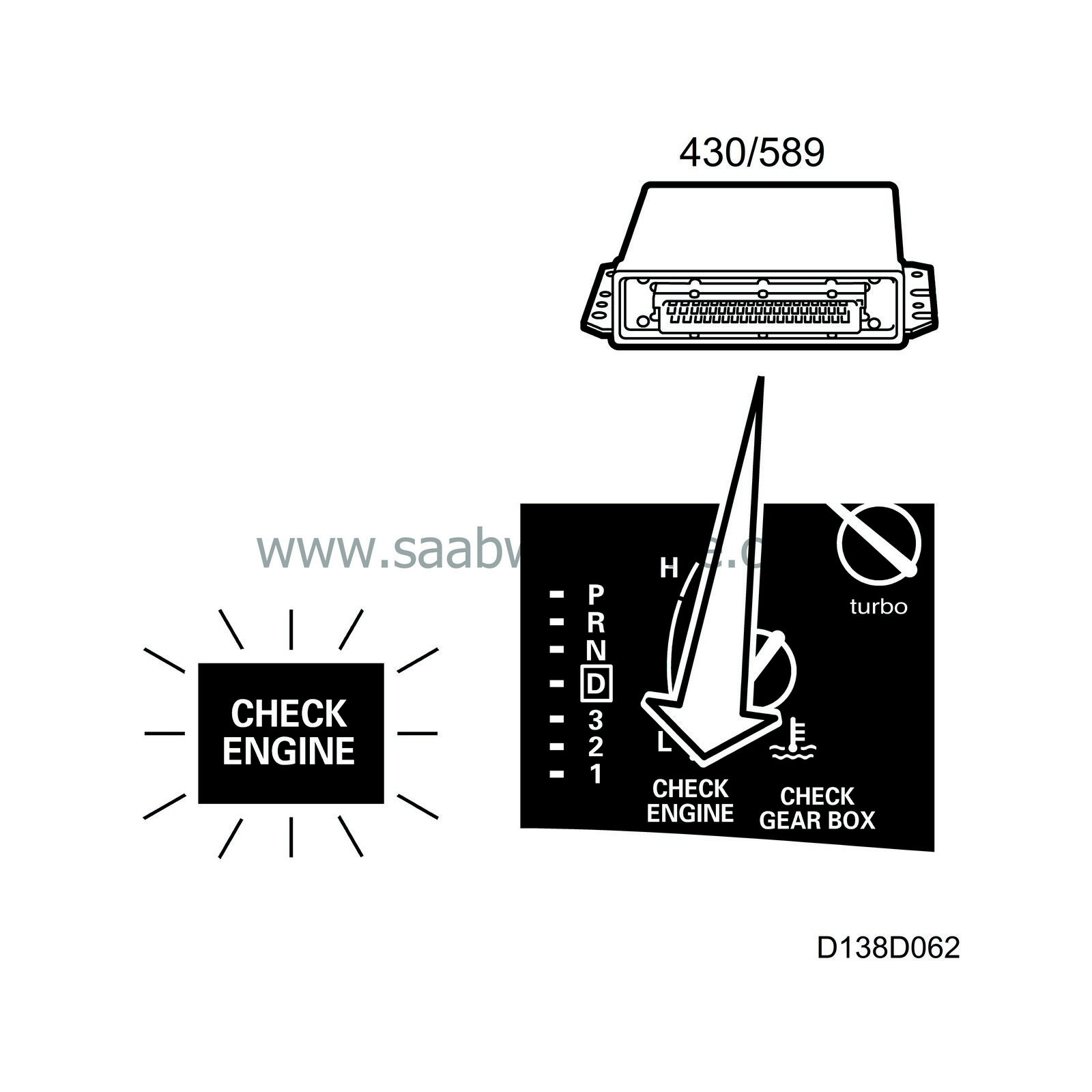
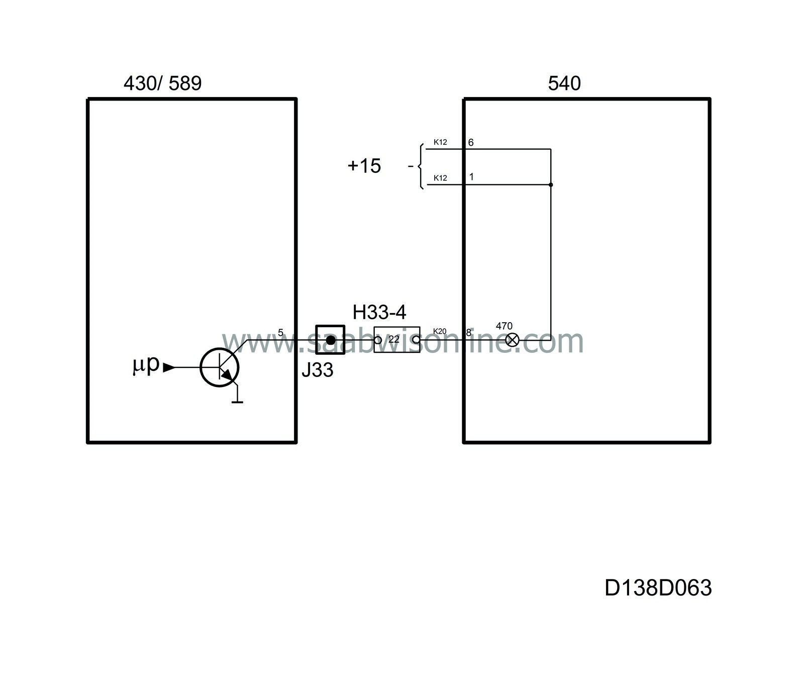
The CHECK ENGINE lamp (MIL) warns the driver when a fault occurs in the engine management system.
The lamp is supplied with current (+15 circuit) in the control module and grounded via terminal 8 (K20) in the engine management system's control module.
In certain markets the transmission control module (TCM) sends a signal to the Trionic requesting it to light the CHECK ENGINE warning lamp (OBDII).
With the ignition ON the lamp remains on until the engine starts. If there are no faults the lamp will go out.
Diagnostics
The function has no diagnostics.| Direction indicator repeater lamps RH and LH |
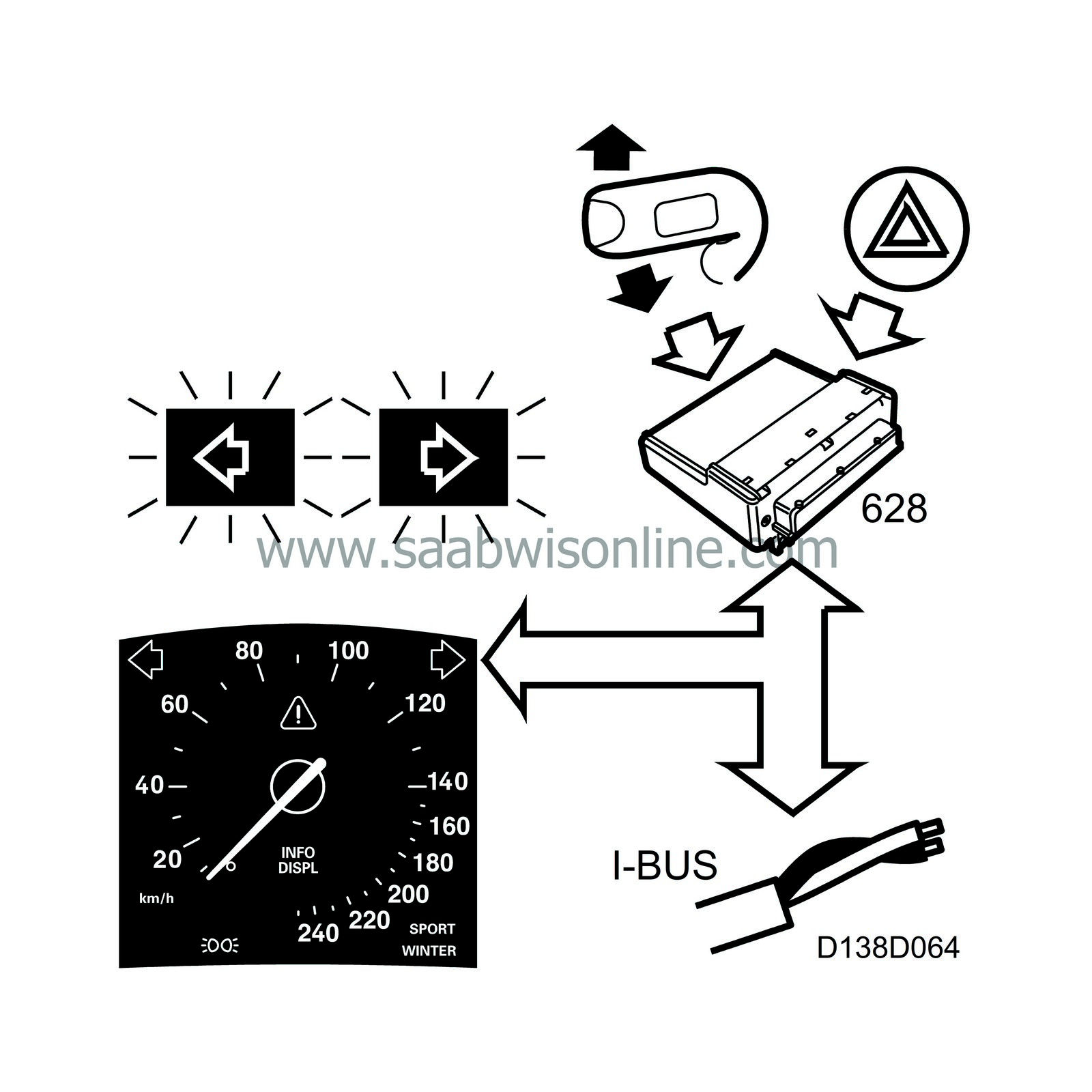
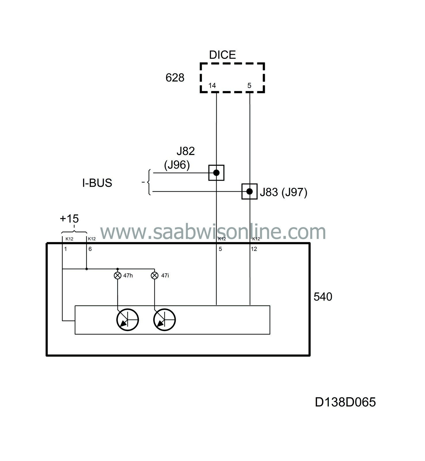
The repeater lamps are situated in the upper part of the main instrument unit and show when the direction indicators are on.
The lamps are supplied with current in the main instrument unit and grounded by the MIU's control module. DICE continuously sends bus information on the status of DIRECTION INDICATORS RIGHT and DIRECTION INDICATORS LEFT, unit ON/OFF.
On receiving DIRECTION INDICATORS ON, the control module grounds the output of the lamp in question which then lights up.
Example
If the LH direction indicators are activated, DICE will change the status of the information DIRECTION INDICATORS LEFT ON/OFF at the same time as the direction indicator lamps are lit. In this way, the main instrument unit control module can synchronize the flashing of the repeater lamps with the direction indicator lamps.The SID also activates the TIC-TAC sound at the same time as the lamps flash.
The function is the same for the RH direction indicators.
| Hazard flashers |
The hazard flashers function is the same as for direction indicators Left/Right except that both lamps are activated at the same time.
When the hazard flashers are activated and the ignition is OFF, the indicator lamps will not flash.
Diagnostics
The function has no diagnostics.| Cruise indicator lamp |
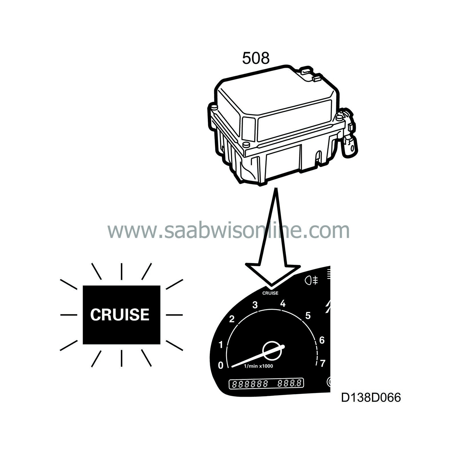
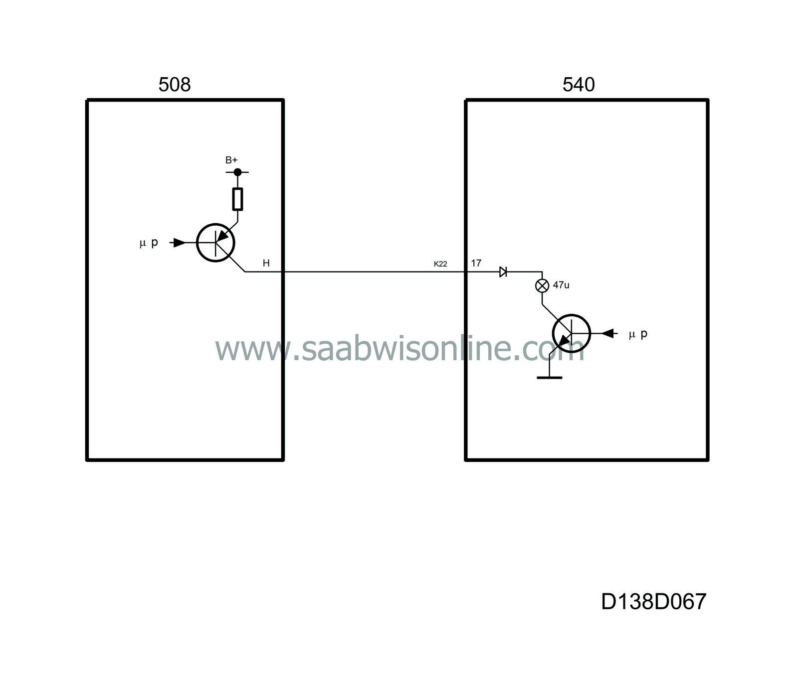
The CRUISE indicator lamp is located in the left-hand part of the main instrument unit. It comes on when the cruise control system is engaged.
The lamp is supplied with current from the cruise control system's control module and grounded in the main instrument unit via terminal 17 (K22).
The CRUISE indicator lamp is also used in diagnostics mode to provide information by means of lamp-flash codes.
Diagnostics
The function has its own diagnostics in the sending system.| SHIFT UP indicator lamp |
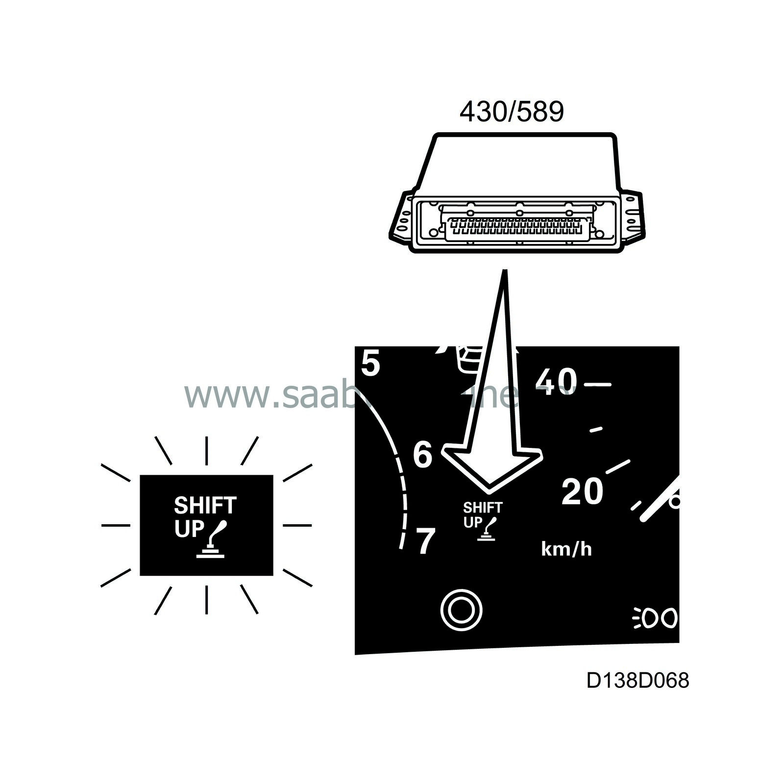
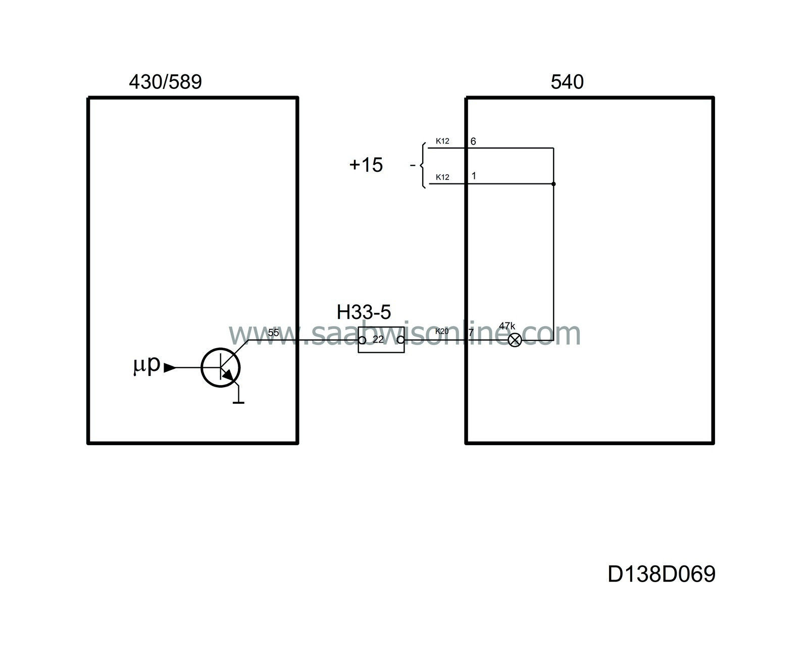
To achieve low fuel consumption, the SHIFT UP indicator lamp in the main instrument unit comes on when a higher gear should be engaged (certain markets).
The lamp is supplied with current (+15 circuit) in the control module and grounded via terminal 7 (K20) in the engine management system's control module.
Diagnostics
The function has its own diagnostics in the sending system.| Lights-on indicator lamp |
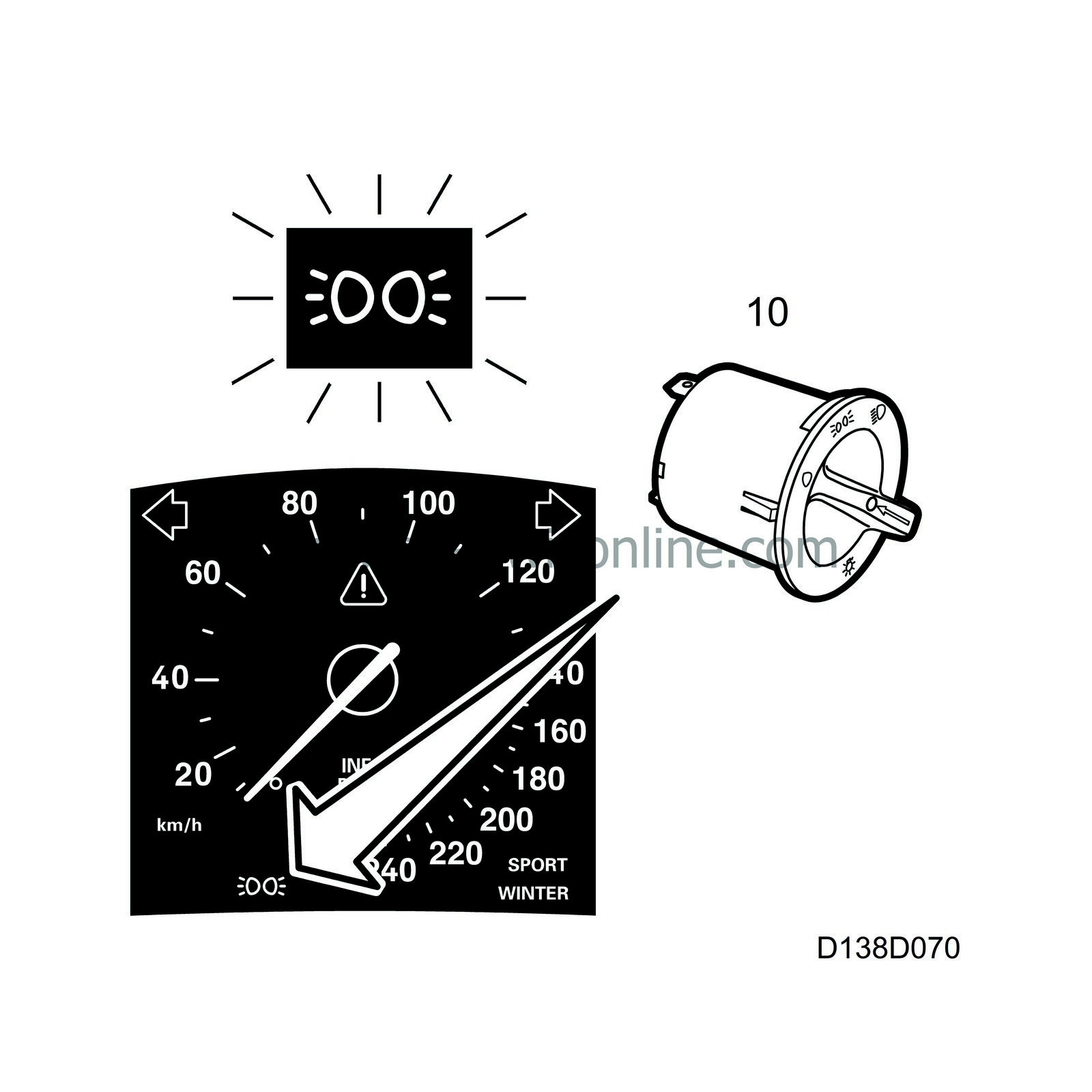
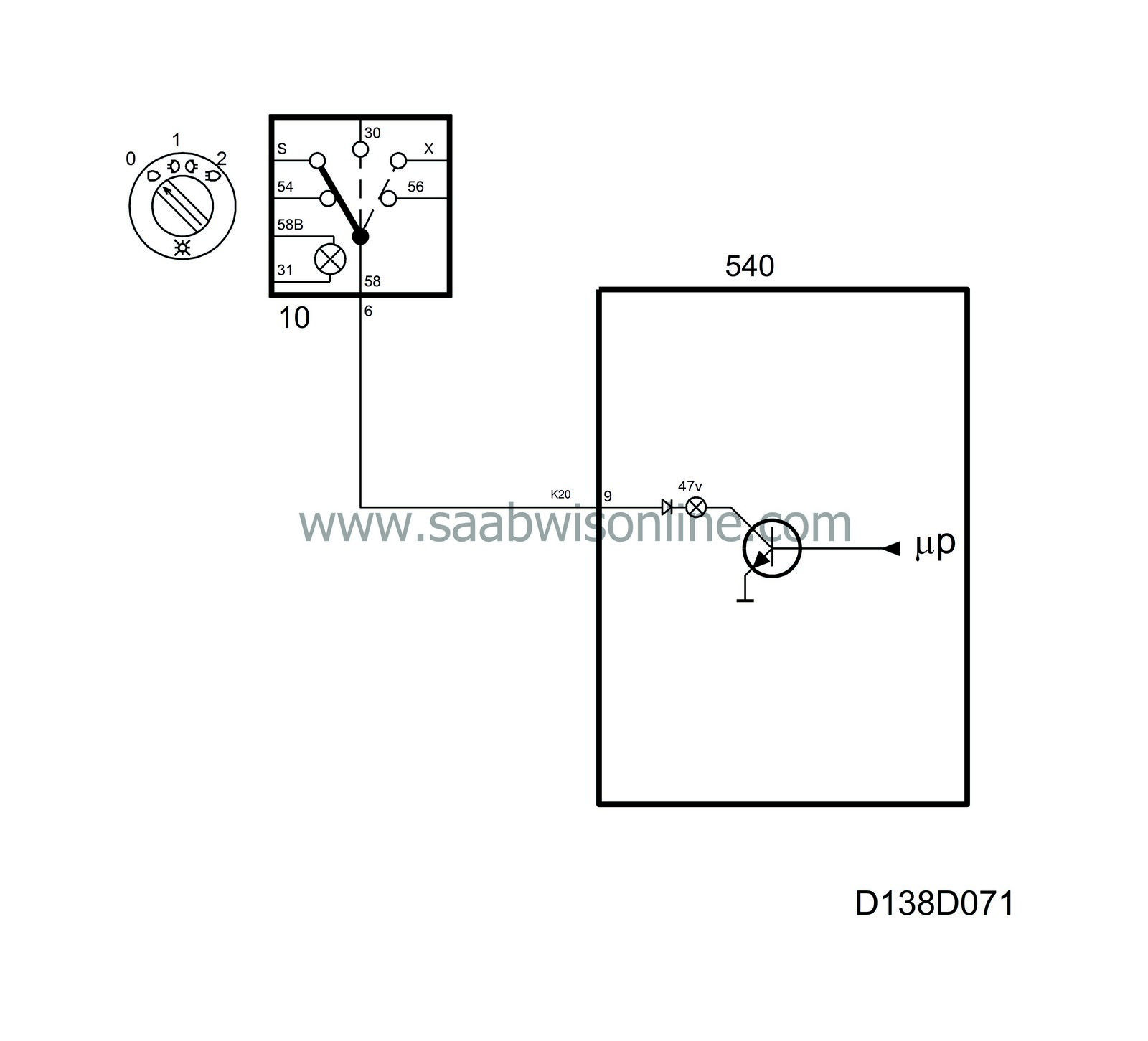
An indicator lamp shows when the headlamps are switched on. The lamp is situated below the speedometer.
The indicator lamp is supplied with current from the lights switch on pin 9 (K20) of the main instrument unit and is grounded in the main instrument unit.
Diagnostics
The function has no diagnostics.| Indicator lamp, rear fog light |
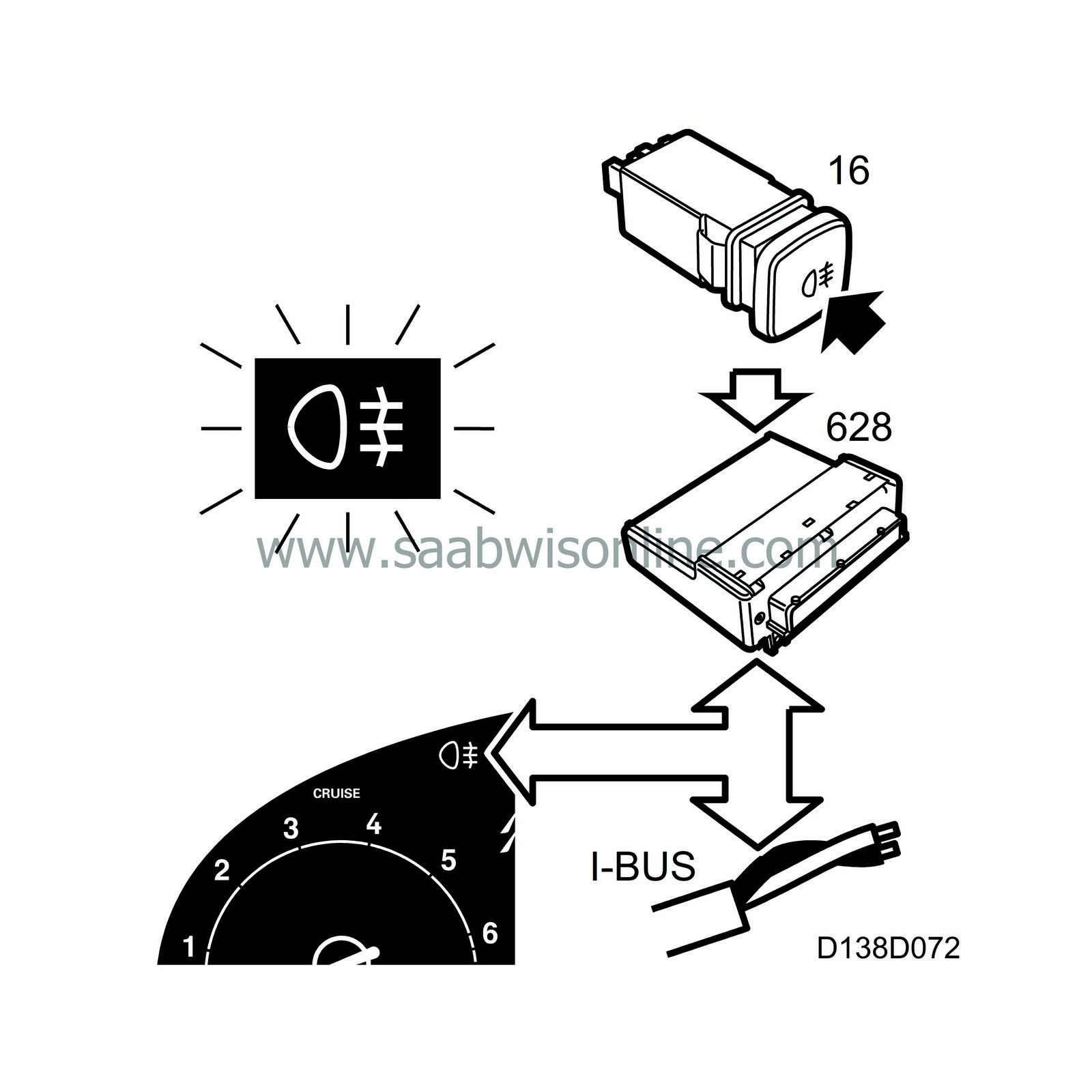
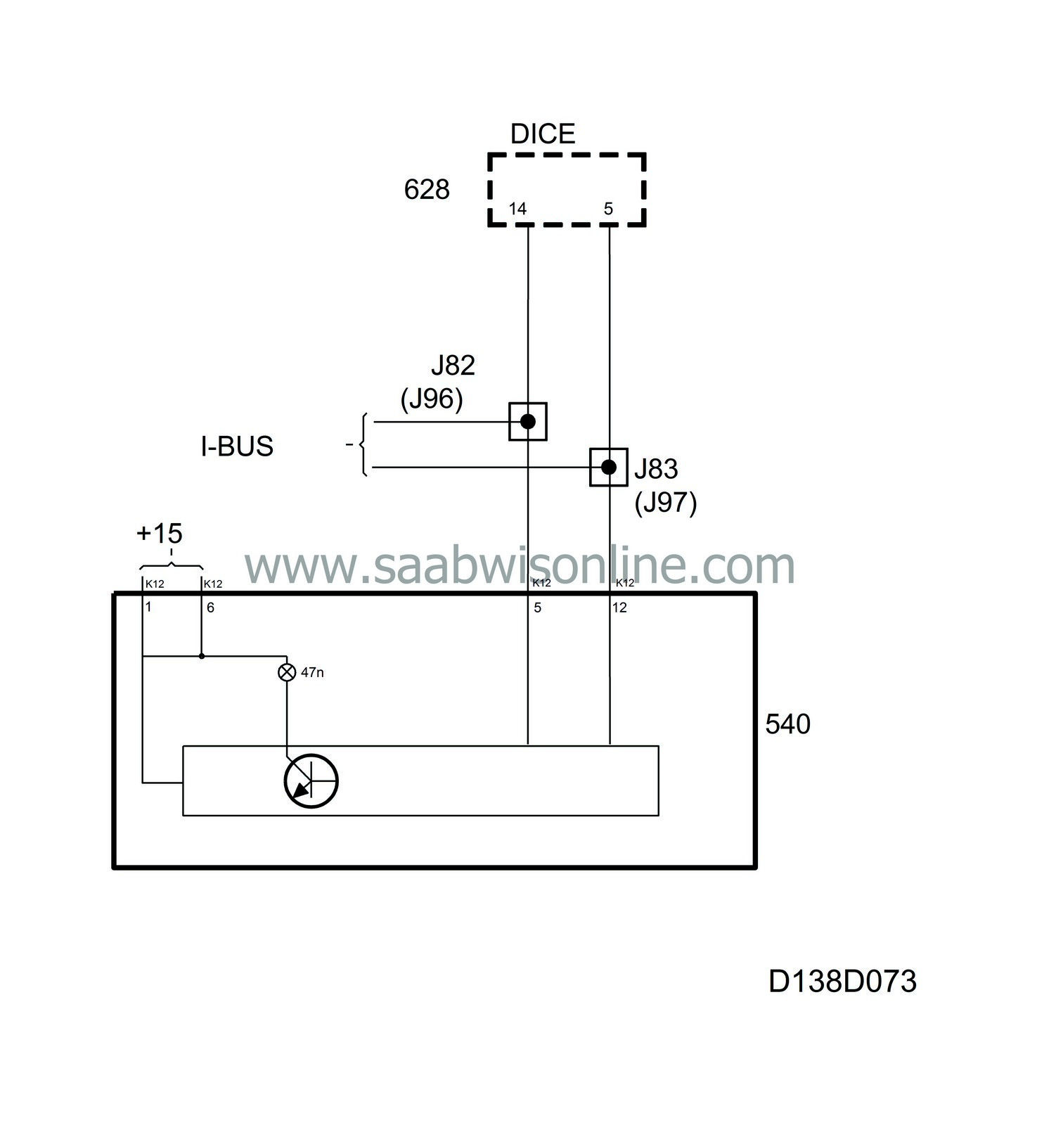
The indicator lamp for the rear fog light is situated in the upper right-hand corner and informs the driver when the rear fog light is switched on.
The lamp is supplied with current in the main instrument unit and grounded by the MIU's control module. DICE continuously sends bus information REAR FOG LIGHT, unit ON/OFF.
On receiving REAR FOG LIGHT ON, the control module grounds the output of the lamp which then lights up.
If DICE changes the status of the bus information to REAR FOG LIGHT OFF, the lamp goes out.
Diagnostics
The function has its own diagnostics in the sending system.| Main beam indicator lamp |
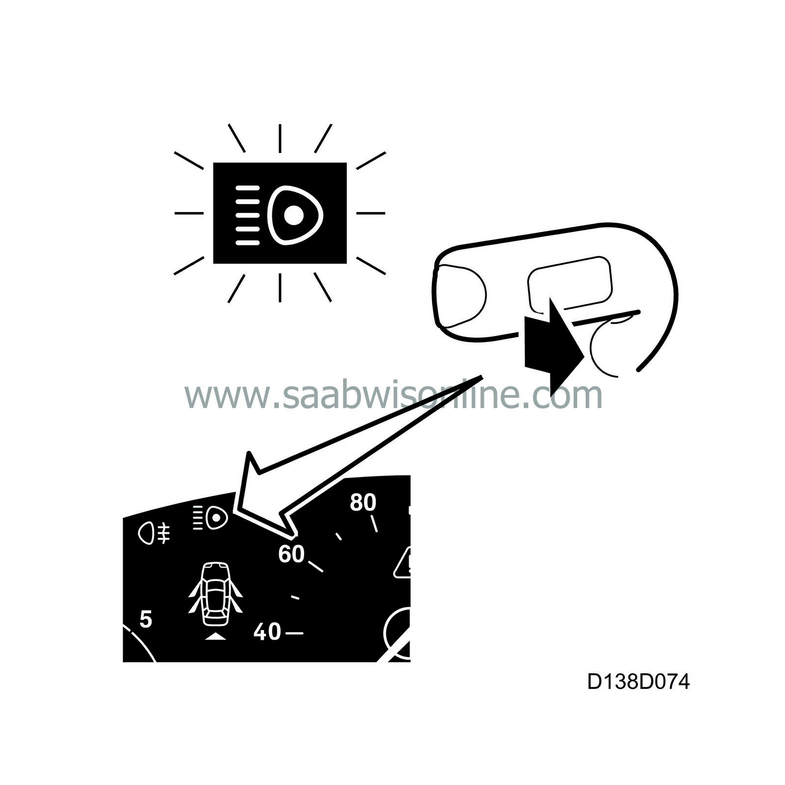
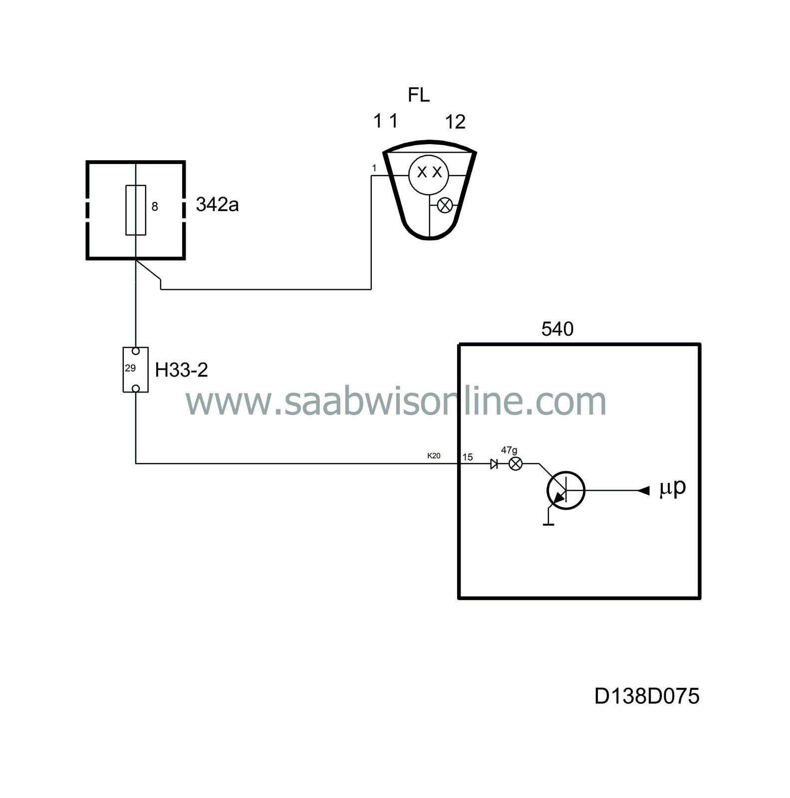
The indicator lamp is situated in the upper left-hand corner and informs the driver that main beams are switched on.
The lamp is supplied with current from main beam fuse 8 on pin 15 (K20) of the main instrument unit and is grounded in the main instrument unit.
Diagnostics
The function has no diagnostics.| Selector lever position indicator |
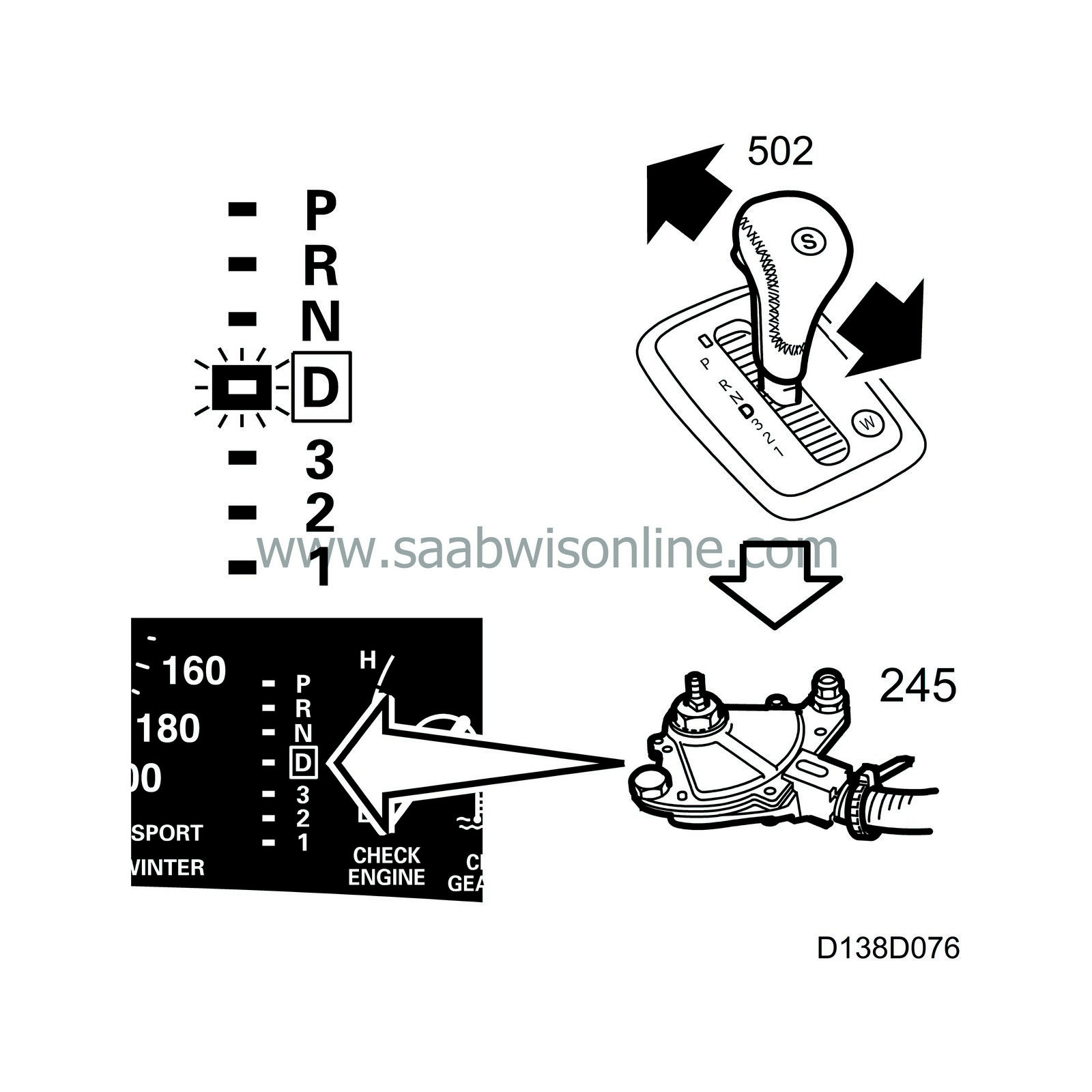
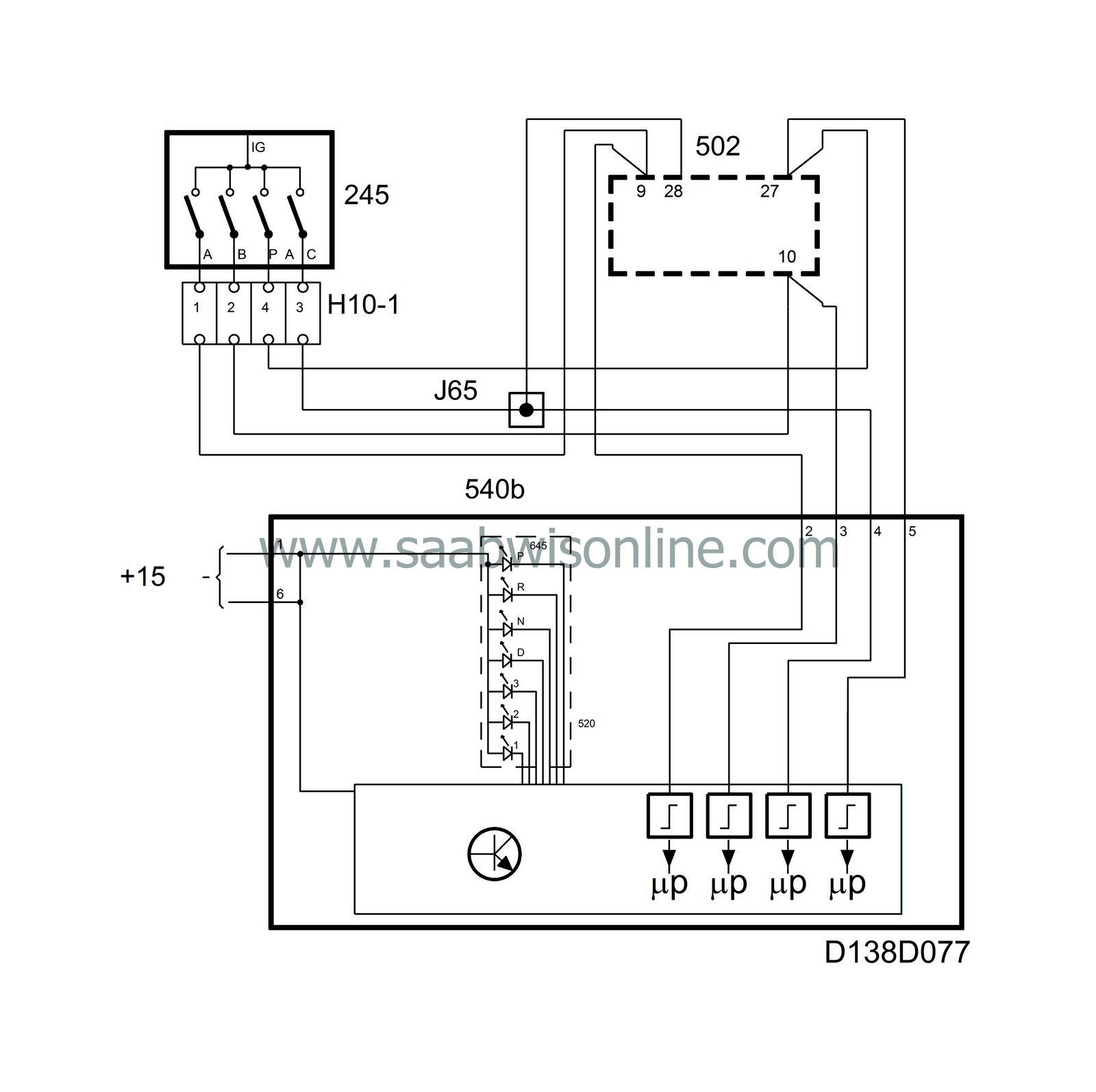
On cars with automatic transmission, the selector lever position indicator shows which gear is selected by lighting up the corresponding gear symbol.
The selector lever position indicator consists of 7 segments, each with an LED beside the corresponding symbol (PRND321). The symbols are illuminated by a lamp, the brightness of which is controlled by the rheostat value.
The LEDs and the lamp are supplied with current in the main instrument unit and grounded by the main instrument unit control module.
The main instrument unit receives information on the selected gear from the selector lever position sensor which is mounted on the transmission casing and controlled by the selector lever. The selector lever position sensor is a position switch which is supplied with current via the +15 circuit. The sensor outputs are supplied with current by 4 sliding contacts which may be either closed (ON) or open (OFF). Different combinations of the A, B, C and PA terminals give the current selector lever position.
|
|
A
|
B
|
C
|
PA
|
|
P
|
ON
|
OFF
|
OFF
|
ON
|
|
R
|
ON
|
ON
|
OFF
|
OFF
|
|
N
|
OFF
|
ON
|
OFF
|
ON
|
|
D
|
OFF
|
ON
|
ON
|
OFF
|
|
3
|
ON
|
ON
|
ON
|
ON
|
|
2
|
ON
|
OFF
|
ON
|
OFF
|
|
1
|
OFF
|
OFF
|
ON
|
ON
|
The following table shows the relationship between internal terminals A, B, C and PA of the selector lever position sensor and the pins of connector H10-1 and the control module.
|
Selector lever position sensor terminals
|
A
|
B
|
C
|
PA
|
|
Control module pins (K22)
|
2
|
3
|
4
|
5
|
Diagnostics
The function has its own diagnostics in the sending system.| Door indication |
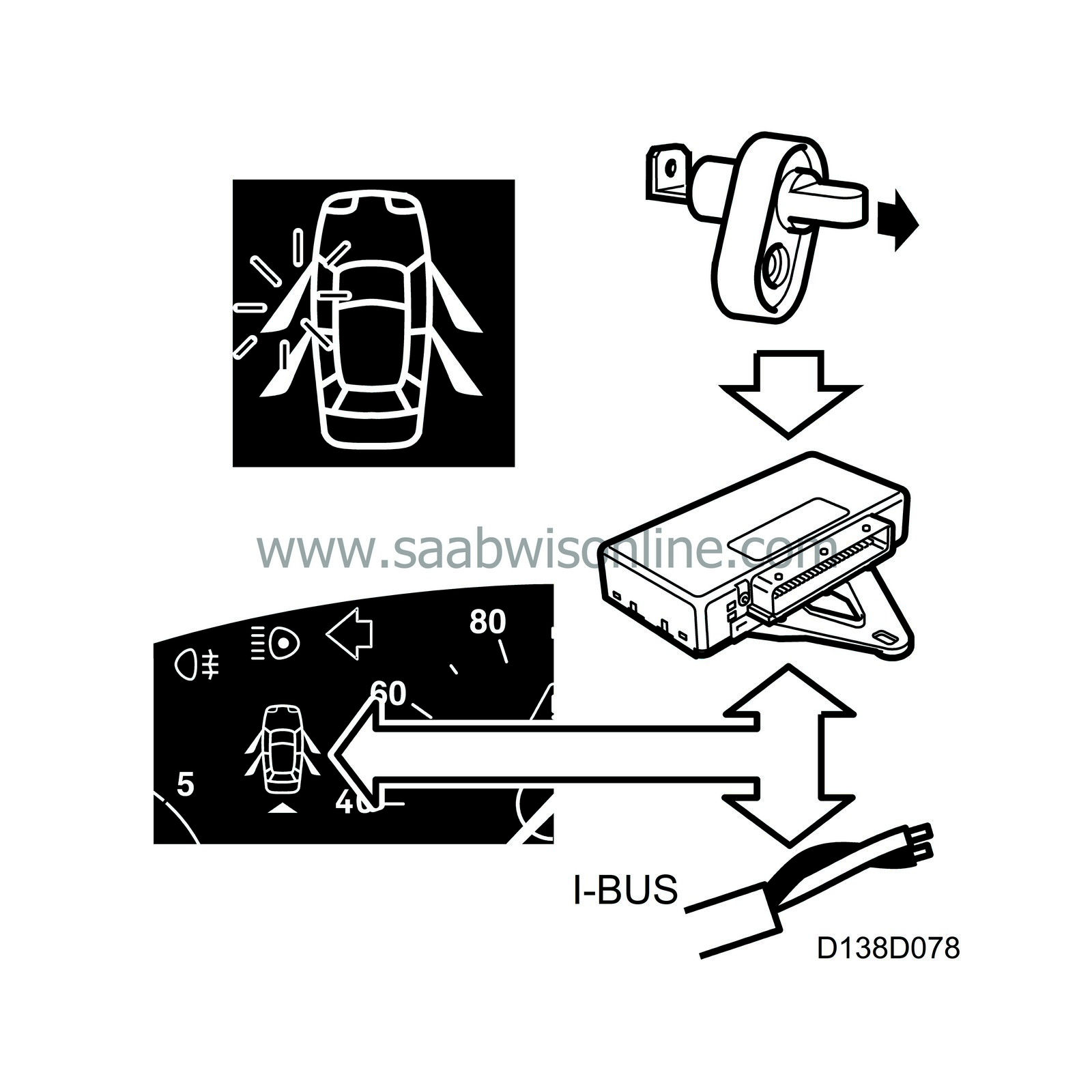
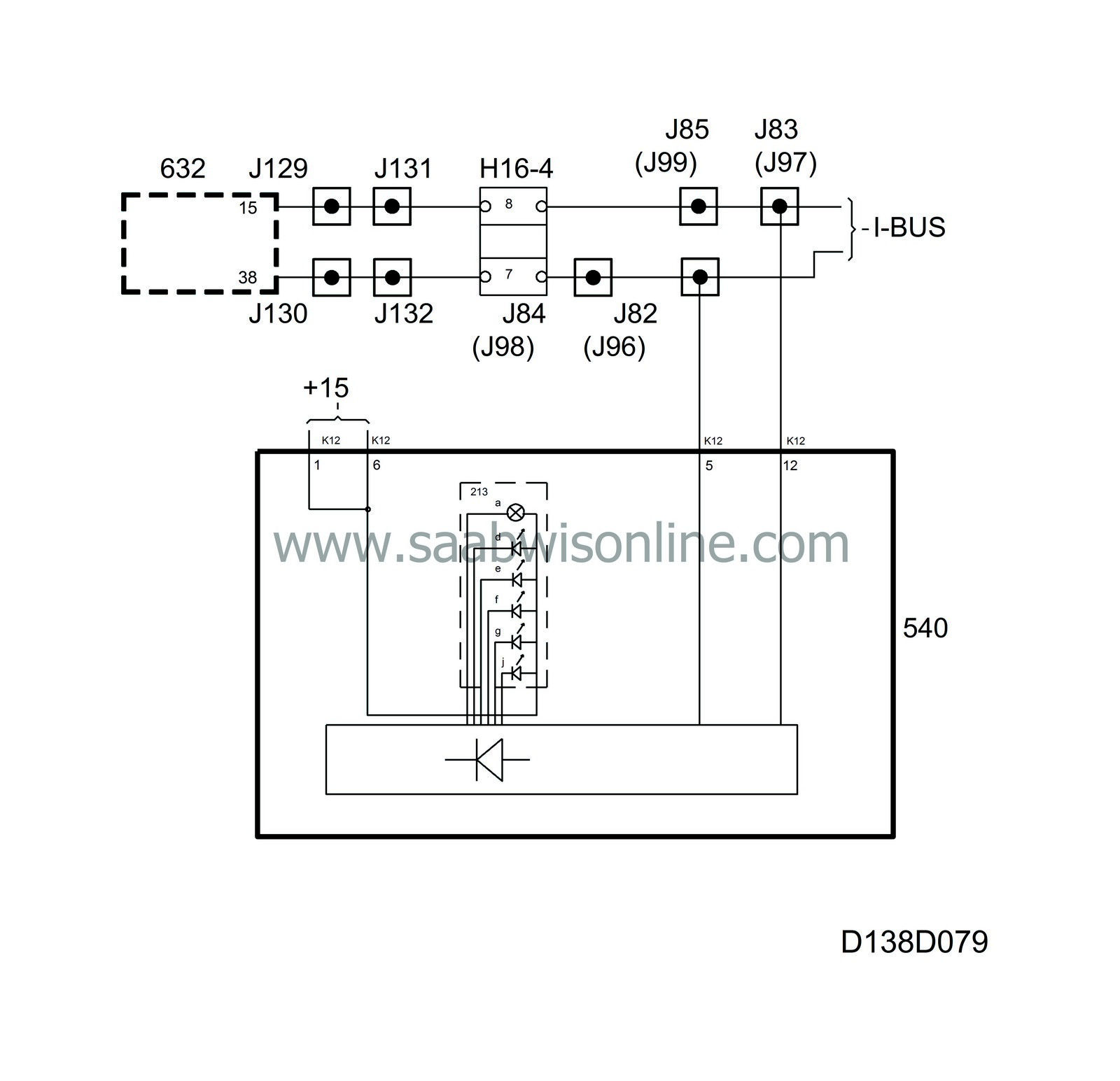
Door indication (on the pictogram) informs the driver if any of the doors or the tailgate is open. It consists of five red LEDs and a lamp. The doors and the tailgate each have an LED. The car is indicated in orange by a lamp.
The LEDs and the lamp are supplied with current in the main instrument unit and grounded by the main instrument unit control module.
TWICE continuously sends bus information on the status of the doors and tailgate, unit OPEN/CLOSED.
Example
When the driver's door is open and the other doors and tailgate are closed, the following information is sent:|
Driver's door
|
Open
|
|
|
Passenger's door
|
Closed
|
|
|
Rear door LH
|
Closed
|
|
|
Rear door RH
|
Closed
|
|
|
Tailgate
|
Closed
|
The main instrument unit control module grounds the outputs of the symbols for the driver's door and the car, which then light up. The other LEDs remain off. The car symbol always lights up if a door or the tailgate is open.

