(391-1949) Handsfree installation and glass-mounted antenna for mobile telephones
|
SERVICE INFORMATION
|
|
Bulletin Nbr:
|
391-1949
|
|
Date:
...........
|
APRIL 1998
|
|
Market:
|
NOT US, CA
|
|
|
Handsfree installation and glass-mounted antenna for mobile telephones
|
Saab 9-3 M98-
Saab 9-3 is ready for installing a mobile telephone. Pre-wiring is available at two levels:
Telephone pre-wiring (Tel 0) and Handsfree pre-wiring (Tel 1). Tel 1 is not available for the Saab 900 Convertible.
Telephone pre-wiring (Tel 0)
means the car is prepared for connecting a mobile telephone via a 10-pin connector in the dashboard. A coaxial cable for the mobile phone antenna is not pre-installed.
Functions provided with telephone pre-wiring include shutting off normal audio system sound during a telephone call (provided the Saab Audio System is used), power supply and battery charging for the mobile telephone and TELEPHONE displayed on SID during a telephone call.
Handsfree pre-wiring (Tel 1)
means the car is prepared for handsfree installation of a mobile telephone via a 10-pin connector in the dashboard. Handsfree installation includes a microphone integrated in the front roof console to improve acoustic qualities, use of the car's existing loudspeaker system (provided the Saab Audio System is fitted) and coaxial cable installed ready for a mobile antenna.
Functions provided with handsfree installation include shutting off normal audio system sound during a telephone call, power supply and battery charging for the telephone, volume of the telephone call adjustable via the volume control on the audio system and TELEPHONE being displayed on SID during a telephone call.
The glass-mounted antenna used by Saab is adapted for GSM 900/1800 and NMT 900 systems.
It is essential that the antenna is mounted according to Saab's recommendations in this SI and the antenna's installation instructions.
This SI contains detailed instructions for installing the following telephones and glass-mounted antenna.
|
-
|
Motorola d 460 on page 8.
|
|
-
|
Motorola Star Tac on page 10.
|
|
-
|
Ericsson GH 600/700 range on page 12.
|
|
-
|
Glass-mounted GSM 900/1800 antenna on page 14.
|
For other telephones, see the wiring diagrams for the respective telephone and handsfree kit.
Refer to the installation instructions for the respective telephone in this SI for a detailed list of parts.
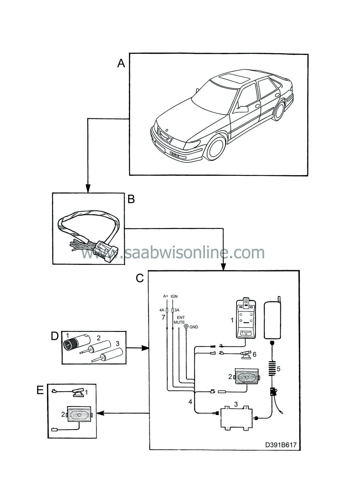
A generalized installation is illustrated on the next page.
|
B.
|
Adapter cable 400 108 130
|
|
C.
|
Handsfree kit (telephone manufacturer's original kit)
|
|
v
|
C.5.
|
Cable set for receiver
|
|
D.
|
Parts to be purchased separately
|
|
v
|
D.1.
|
Antenna cable adapter
|
|
v
|
D.2.
|
Microphone jack plug
|
|
v
|
D.3.
|
Loudspeaker jack plug
|
|
E.
|
Parts in handsfree kit not used
|
Installation of NOKIA 2110
Parts required

|
-
|
400 109 179 Adapter cable
|
|
-
|
50 36 850 Installation instructions for adapter cable (included in kit 400 109 179)
|
|
-
|
Antenna cable adapter (purchased separately)
|
|
-
|
NOKIA 2110 original handsfree kit (purchased separately)
|
|
-
|
3.5 jack plug (mono) for loudspeaker (purchased separately)
|
|
-
|
2.5 mm jack plug (mono) for microphone (purchased separately)
|
|
-
|
Shrink sleeve Ø 3 mm, approx. 150 mm
|
|
-
|
50 36 348 Installation instructions for telephone console 9-3 (included in kit 400 110 334/342)
|
|
Note
|
|
Mark the adapter cable wires with the correct pin numbers before commencing.
|
|
1.
|
Refer to installation instructions 50 36 850 up to and including step 6.
|
|
2.
|
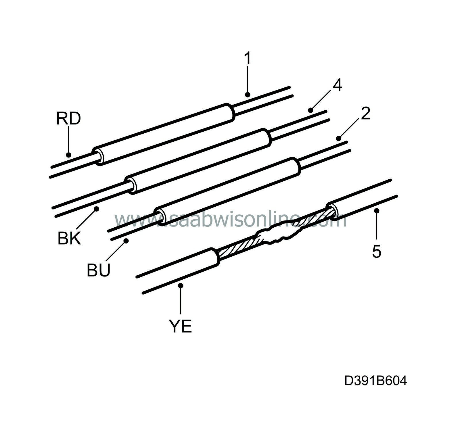
New step 7:
|
|
|
2.a.
|
Make sure there is
not
a wire present in the adapter cable connector, pos. 6.
If there is a wire present, remove the pin to the black wire pos. 8 and transfer the blue/white wire from pos. 6 to pos. 8 in the adapter cable connector.
|
|
|
2.b.
|
Fit a piece of shrink sleeve over the red wire on the adapter cable and solder together the red wire from the telephone handsfree kit and the red wire on the adapter cable in pos. 1. Cover the solder with the shrink sleeve and heat it.
|
|
|
2.c.
|
Fit a piece of shrink sleeve over the black wire on the adapter cable and solder together the black wire from the telephone handsfree kit and the black wire on the adapter cable in pos. 4. Cover the solder with the shrink sleeve and heat it.
|
|
|
2.d.
|
Fit a piece of shrink sleeve over the blue/red wire on the adapter cable and solder together the blue wire from the telephone handsfree kit and the blue/red wire on the adapter cable in pos. 2. Cover the solder with the shrink sleeve and heat it.
|
|
|
2.e.
|
Fit a piece of shrink sleeve over the yellow wire on the adapter cable and solder together the yellow wire from the telephone handsfree kit and the yellow wire on the adapter cable in pos. 5. Cover the solder with the shrink sleeve and heat it.
|
|
|
2.f.
|
Microphone:

Determine (+) and (-) on the jack plug terminals with an ohmmeter.
Solder the brown/grey wire on the adapter cable, pos. 10, to the jack plug (+) terminal.
Solder the green wire on the adapter cable, pos. 3, to the jack plug (-) terminal.
|
|
|
2.g.
|
Loudspeaker:
Determine (+) and (-) on the jack plug terminals with an ohmmeter.
Solder the grey/white wire on the adapter cable, pos. 7, to the jack plug (+) terminal.
Solder the blue/white wire on the adapter cable, pos. 8, to the jack plug (-) terminal.
|
|
|
2.h.
|
Plug the microphone and speaker jack plugs into the telephone handsfree unit.
|
|
|
2.i.
|
Connect the antenna cable to the antenna cable on the telephone handsfree unit with the adapter.
|
|
|
2.j.
|
Continue with installation instructions 50 36 850 steps 8-11.
|
|
3.
|
Then, fit the telephone console as described in installation instructions 50 36 348.
|
Installation of NOKIA 1610
Parts required
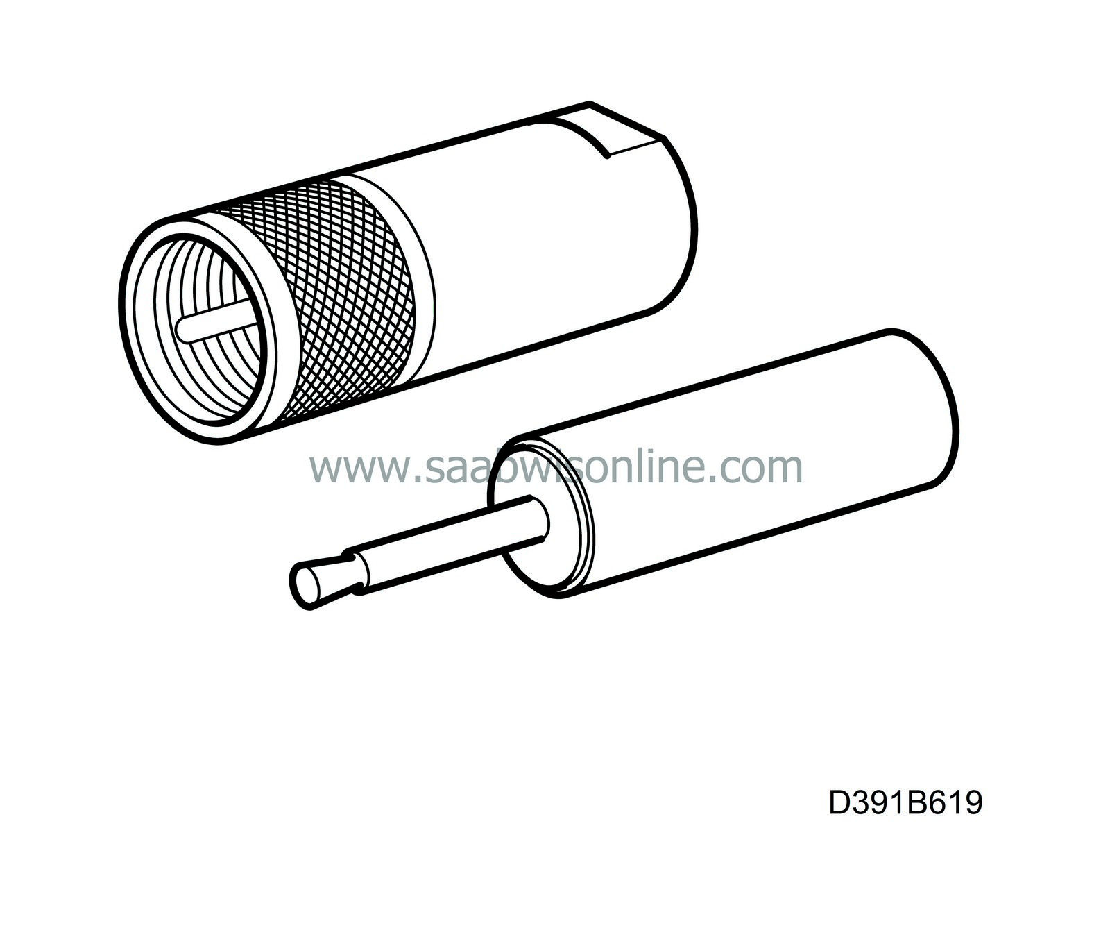
|
-
|
400 109 179 Adapter cable
|
|
-
|
50 36 850 Installation instructions for adapter cable (included in kit 400 109 179)
|
|
-
|
Antenna cable adapter (purchased separately)
|
|
-
|
NOKIA 1610 original handsfree kit (purchased separately)
|
|
-
|
2.5 mm jack plug (mono) for microphone (purchased separately)
|
|
-
|
Shrink sleeve Ø 3 mm, approx. 70 mm
|
|
-
|
50 36 348 Installation instructions for telephone console 9-3 (included in kit 400 110 334/342)
|
The car's loudspeaker system is not used
.
|
Note
|
|
Mark the adapter cable wires with the correct pin numbers before commencing.
|
|
1.
|
Refer to installation instructions 50 36 850 up to and including step 6.
|
|
2.
|
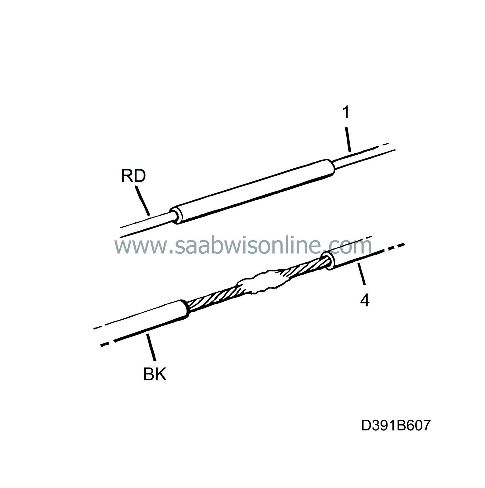
New step 7:
|
|
|
2.a.
|
Make sure there is
not
a wire present in the adapter cable connector, pos. 6.
If there is a wire present, remove the pin to the black wire pos. 8 and transfer the blue/white wire from pos. 6 to pos. 8 in the adapter cable connector.
|
|
|
2.b.
|
Fit a piece of shrink sleeve over the red wire on the adapter cable and solder together the red wire from the telephone handsfree kit and the red wire on the adapter cable in pos. 1. Cover the solder with the shrink sleeve and heat it.
|
|
|
2.c.
|
Fit a piece of shrink sleeve over the black wire on the adapter cable and solder together the black wire from the telephone handsfree kit and the black wire on the adapter cable in pos. 4. Cover the solder with the shrink sleeve and heat it.
|
|
|
2.d.
|
Microphone:
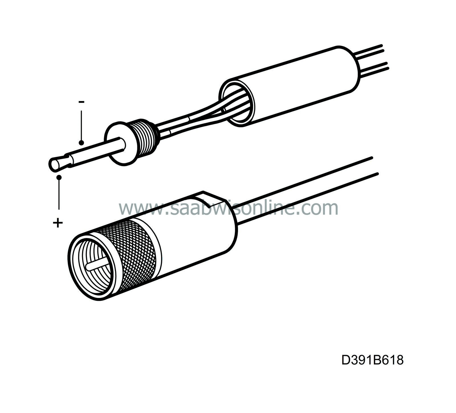
Determine (+) and (-) on the jack plug terminals with an ohmmeter.
Solder the brown/grey wire on the adapter cable, pos. 10, to the jack plug (+) terminal.
Solder the green wire on the adapter cable, pos. 3, to the jack plug (-) terminal.
|
|
|
2.e.
|
Connect the microphone jack to the telephone handsfree unit.
|
|
|
2.f.
|
Connect the antenna cable to the antenna cable on the telephone handsfree unit with the adapter.
|
|
|
2.g.
|
Continue with installation instructions 50 36 850 steps 8-11.
|
|
3.
|
Then, fit the telephone console as described in installation instructions 50 36 348.
|
Installation of Motorola d 460
Parts required

|
-
|
400 109 179 Adapter cable
|
|
-
|
50 36 850 Installation instructions for adapter cable (included in kit 400 109 179)
|
|
-
|
Antenna cable adapter (purchased separately)
|
|
-
|
Motorola d 460 original handsfree kit (purchased separately)
|
|
-
|
Shrink sleeve Ø 3 mm, approx. 220 mm
|
|
-
|
50 36 348 Installation instructions for telephone console 9-3 (included in kit 400 110 334/342)
|
The connectors included with the telephone handsfree kit are used when installing the microphone and speaker.
|
Note
|
|
Mark the adapter cable wires with the correct pin numbers before commencing.
|
|
1.
|
Refer to installation instructions 50 36 850 up to and including step 6.
|
|
2.
|
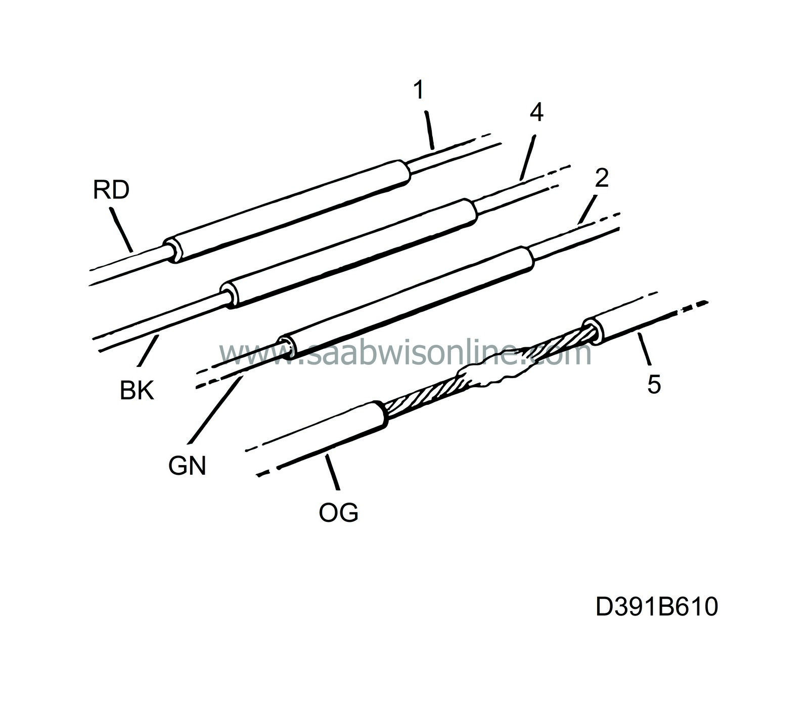
New step 7:
|
|
|
2.a.
|
Make sure there is
not
a wire present in the adapter cable connector, pos. 6.
If there is a wire present, remove the pin to the black wire pos. 8 and transfer the blue/white wire from pos. 6 to pos. 8 in the adapter cable connector.
|
|
|
2.b.
|
Fit a piece of shrink sleeve over the red wire on the adapter cable and solder together the red wire from the telephone handsfree kit and the red wire on the adapter cable in pos. 1. Cover the solder with the shrink sleeve and heat it.
|
|
|
2.c.
|
Fit a piece of shrink sleeve over the black wire on the adapter cable and solder together the black wire from the telephone handsfree kit and the black wire on the adapter cable in pos. 4. Cover the solder with the shrink sleeve and heat it.
|
|
|
2.d.
|
Fit a piece of shrink sleeve over the blue/red wire on the adapter cable and solder together the green wire from the telephone handsfree kit and the blue/red wire on the adapter cable in pos. 2. Cover the solder with the shrink sleeve and heat it.
|
|
|
2.e.
|
Fit a piece of shrink sleeve over the yellow wire on the adapter cable and solder together the orange wire from the telephone handsfree kit and the yellow wire on the adapter cable in pos. 5. Cover the solder with the shrink sleeve and heat it.
|
|
|
2.f.
|
Microphone:

|
Important
|
|
Take care when soldering the microphone cable. The heat can melt the plastic.
|
|
|
Cut off the connector for the microphone in the handsfree kit. Fit a piece of shrink sleeve over the green wire on the adapter cable, pos. 3, and solder together the microphone cable screen and the green wire on the adapter cable, pos. 3. Cover the solder with the shrink sleeve and heat it carefully.
Fit a piece of shrink sleeve over the brown/grey wire on the adapter cable, pos. 10, and solder together the microphone cable wire and the brown/grey wire on the adapter cable, pos. 10. Cover the solder with the shrink sleeve and heat it carefully.
|
|
|
2.g.
|
Loudspeaker:
|
Note
|
|
Before cutting off the connector for the speakers in the handsfree kit: Open the speaker and determine and mark the terminals with (+) and (-).
|
Solder the grey/white wire on the adapter cable, pos. 7, to the (+) terminal on the connector.
Solder the blue/white wire on the adapter cable, pos. 8, to the (-) terminal on the connector.
|
|
|
2.h.
|
Plug the microphone and speaker connectors into the telephone handsfree unit.
|
|
|
2.i.
|
Connect the antenna cable to the antenna cable on the telephone handsfree unit with the adapter.
|
|
|
2.j.
|
Continue with installation instructions 50 36 850 steps 8-11.
|
|
3.
|
Then, fit the telephone console as described in installation instructions 50 36 348.
|
Installation of Motorola Star Tac
Parts required

|
-
|
400 109 179 Adapter cable
|
|
-
|
50 36 850 Installation instructions for adapter cable (included in kit 400 109 179)
|
|
-
|
Antenna cable adapter (purchased separately)
|
|
-
|
Motorola Star Tac original handsfree kit (purchased separately)
|
|
-
|
3.5 jack plug (mono) for loudspeaker (purchased separately)
|
|
-
|
2.5 mm jack plug (mono) for microphone (purchased separately)
|
|
-
|
Shrink sleeve Ø 3 mm, approx. 150 mm
|
|
-
|
50 36 348 Installation instructions for telephone console 9-3 (included in kit 400 110 334/342)
|
|
Note
|
|
Mark the adapter cable wires with the correct pin numbers before commencing.
|
|
1.
|
Refer to installation instructions 50 36 850 up to and including step 6.
|
|
2.
|
New step 7:

|
|
|
2.a.
|
Make sure there is
not
a wire present in the adapter cable connector, pos. 6.
If there is a wire present, remove the pin to the black wire pos. 8 and transfer the blue/white wire from pos. 6 to pos. 8 in the adapter cable connector.
|
|
|
2.b.
|
Fit a piece of shrink sleeve over the red wire on the adapter cable and solder together the red wire from the telephone handsfree kit and the red wire on the adapter cable in pos. 1. Cover the solder with the shrink sleeve and heat it.
|
|
|
2.c.
|
Fit a piece of shrink sleeve over the black wire on the adapter cable and solder together the black wire from the telephone handsfree kit and the black wire on the adapter cable in pos. 4. Cover the solder with the shrink sleeve and heat it.
|
|
|
2.d.
|
Fit a piece of shrink sleeve over the blue/red wire on the adapter cable and solder together the green wire from the telephone handsfree kit and the blue/red wire on the adapter cable in pos. 2. Cover the solder with the shrink sleeve and heat it.
|
|
|
2.e.
|
Fit a piece of shrink sleeve over the yellow wire on the adapter cable and solder together the orange wire from the telephone handsfree kit and the yellow wire on the adapter cable in pos. 5. Cover the solder with the shrink sleeve and heat it.
|
|
|
2.f.
|
Microphone:

Determine (+) and (-) on the jack plug terminals with an ohmmeter.
Solder the brown/grey wire on the adapter cable, pos. 10, to the jack plug (+) terminal.
Solder the green wire on the adapter cable, pos. 3, to the jack plug (-) terminal.
|
|
|
2.g.
|
Loudspeaker:
Determine (+) and (-) on the jack plug terminals with an ohmmeter.
Solder the grey/white wire on the adapter cable, pos. 7, to the jack plug (+) terminal.
Solder the blue/white wire on the adapter cable, pos. 8, to the jack plug (-) terminal.
|
|
|
2.h.
|
Plug the microphone and speaker jack plugs into the telephone handsfree unit.
|
|
|
2.i.
|
Connect the antenna cable to the antenna cable on the telephone handsfree unit with the adapter.
|
|
|
2.j.
|
Continue with installation instructions 50 36 850 steps 8-11.
|
|
3.
|
Then, fit the telephone console as described in installation instructions 50 36 348.
|
Installation of Ericsson GH 600/700 range
Parts required

|
-
|
400 109 179 Adapter cable
|
|
-
|
50 36 850 Installation instructions for adapter cable (included in kit 400 109 179)
|
|
-
|
Antenna cable adapter (purchased separately)
|
|
-
|
Ericsson GH 600/700 range original handsfree kit (purchased separately)
|
|
-
|
3.5 jack plug (mono) for loudspeaker (purchased separately)
|
|
-
|
3.5 jack plug (stereo) for microphone (purchased separately)
|
|
-
|
Mute cable KRY 11093-02 (Ericsson part no., purchased separately)
|
|
-
|
Antenna cable adapter (purchased separately)
|
|
-
|
Shrink sleeve Ø 3 mm, approx. 90 mm
|
|
-
|
50 36 348 Installation instructions for telephone console 9-3 (included in kit 400 110 334/342)
|
|
Note
|
|
Mark the adapter cable wires with the correct pin numbers before commencing.
|
|
1.
|
Refer to installation instructions 50 36 850 up to and including step 6.
|
|
2.
|
New step 7:

|
|
|
2.a.
|
Make sure there is
not
a wire present in the adapter cable connector, pos. 6.
If there is a wire present, remove the pin to the black wire pos. 8 and transfer the blue/white wire from pos. 6 to pos. 8 in the adapter cable connector.
|
|
|
2.b.
|
Fit a piece of shrink sleeve over the red wire on the adapter cable and solder together the red wire from the telephone handsfree kit and the red wire on the adapter cable in pos. 1. Cover the solder with the shrink sleeve and heat it.
|
|
|
2.c.
|
Fit a piece of shrink sleeve over the black wire on the adapter cable and solder together the black wire from the telephone handsfree kit and the black wire on the adapter cable in pos. 4. Cover the solder with the shrink sleeve and heat it.
|
|
|
2.d.
|
Fit a piece of shrink sleeve over the yellow wire on the adapter cable and solder together the mute cable and the yellow wire on the adapter cable in pos. 5. Cover the solder with the shrink sleeve and heat it.
|
|
|
2.e.
|
Microphone:

Determine (+) and (-) on the jack plug terminals with an ohmmeter.
Solder the brown/grey wire on the adapter cable, pos. 10, to the jack plug (+) terminal.
Solder the green wire on the adapter cable, pos. 3, to the jack plug (-) terminal.
|
|
|
2.f.
|
Loudspeaker:
Determine (+) and (-) on the jack plug terminals with an ohmmeter.
Solder the grey/white wire on the adapter cable, pos. 7, to the jack plug (+) terminal.
Solder the blue/white wire on the adapter cable, pos. 8, to the jack plug (-) terminal.
|
|
|
2.g.
|
Plug the microphone and speaker jack plugs into the telephone handsfree unit.
|
|
|
2.h.
|
Connect the antenna cable to the antenna cable on the telephone handsfree unit with the adapter.
|
|
|
2.i.
|
Continue with installation instructions 50 36 850 steps 8-11.
|
|
3.
|
Then, fit the telephone console as described in installation instructions 50 36 348.
|
Glass-mounted antenna Saab 9-3, 3D and 5D
A glass-mounted antenna for the Saab 9-3, 3D and 5D is under development and will be available as a stock item from week 818.
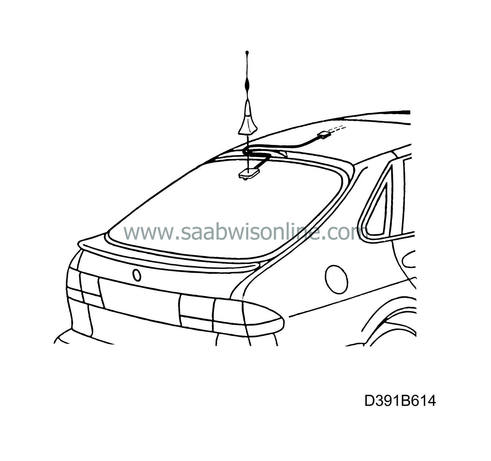
The kit will have the following part number and installation instructions number:
400 111 647 Telephone antenna, glass-mounted
50 41 447 Installation instructions
There are no alternative locations for the glass-mounted antenna. The location shown in the installation instructions is the optimum.
The adhesive used for glass mounting has a service life of 3 years.
Glass mounted antenna Saab 9-3, convertible
There are no alternative locations for the glass-mounted antenna on the convertible. The location shown in installation instructions 48 72 776 for kit 400 109 187 is the optimum; on the passenger side window (available as stock item week 817).
The adhesive used for glass mounting has a service life of 3 years.
|
Warranty/Time Information
|
Failed Object: 939 20
Location code: 09
Repair/Action code: 10


