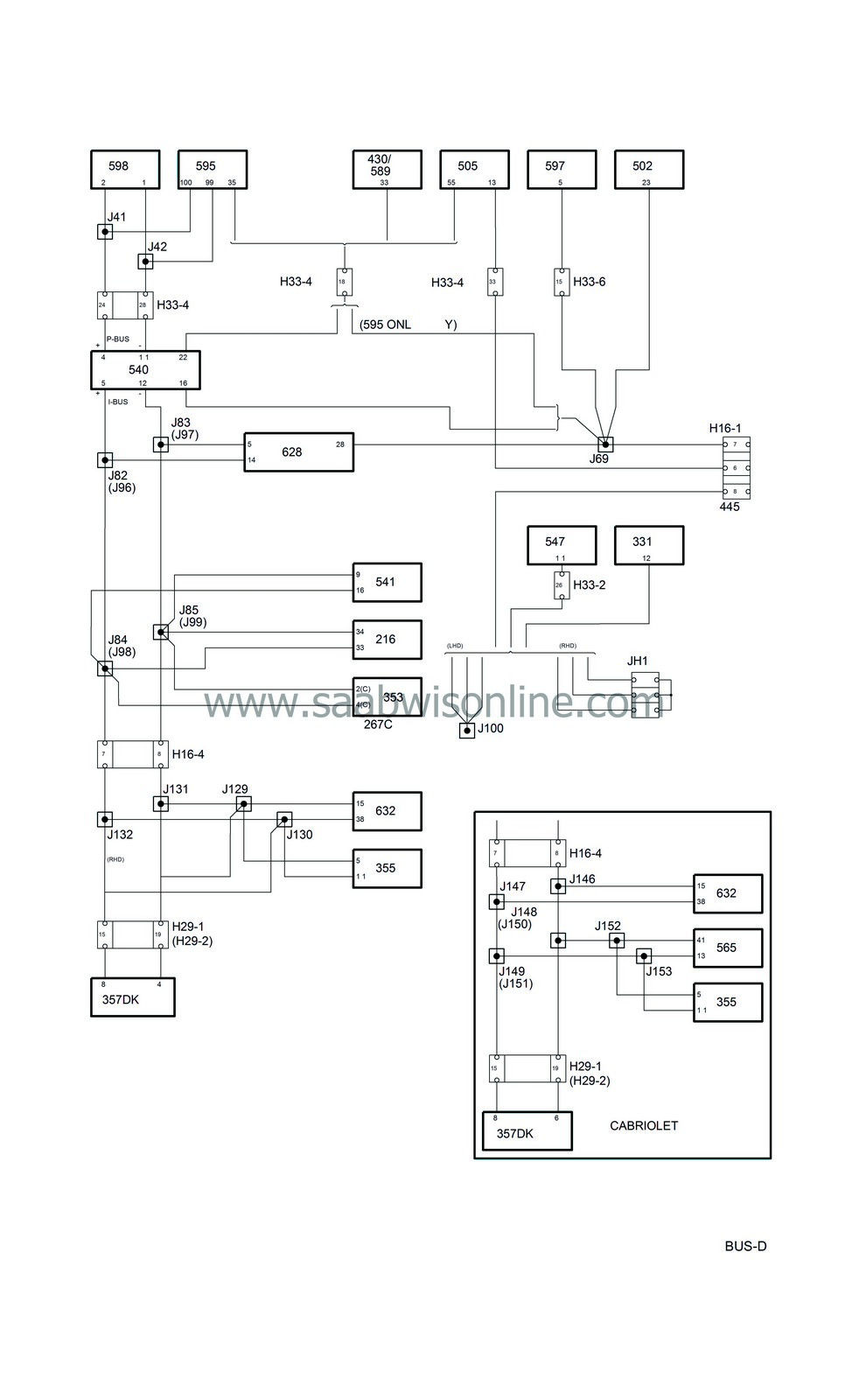
Bus communication
| Bus communication |
| • |
Control module ACC (216)
|
|
| • |
Radio connector C (267c)
|
|
| • |
Control module airbag/SRS (331)
|
|
| • |
Radio (353)
|
|
| • |
CD changer (355)
|
|
| • |
Control module PSM (357Dk)
|
|
| • |
Control module, TRIONIC (430)
|
|
| • |
Control module, TCM (502)
|
|
| • |
Control module M2.10.3 (505)
|
|
| • |
MIU (540)
|
|
| • |
SID (541)
|
|
| • |
Control module, ABS (547)
|
|
| • |
Control module STC (565)
|
|
| • |
Control module, Trionic OBDII (589)
|
|
| • |
Control module EDC 15 (595)
|
|
| • |
Control module, extra heater (597)
|
|
| • |
Diesel pump (598)
|
|
| • |
Control module, DICE (628)
|
|
| • |
Control module, TWICE (632)
|
|
| P-bus and I-bus |

By bus is meant leads in which information is transmitted digitally and serially. By digital is meant that the voltage difference between the two leads can have only two values, approx. 0 and 5 V. The information is coded so that different combinations of pulses with the values 0 and 5 V mean different things.
Serial means that the information is sent in ”packets” which are transmitted one after the other in rapid succession.
Half of the control modules in the Saab 9-3 are connected to the bus.
The buses consist of a P-bus (Power-train Bus) and an I-bus (Instrument Bus). Both buses are connected to the MIU (main Instrument Unit). The buses are electrically isolated from each other.
The diagnostic tool is not connected directly to the bus but communicates via the DICE, one of the control modules connected to the I-bus, and so has access to all control modules connected to the bus.
The data transmission rate of the P-bus is ten times greater than that of the I-bus. The reason for this is that the power-train system requires information with the minimum possible delay.
All the information sent from one control module is accessible for all other control modules on the bus. The MIU is responsible for ensuring that information available on one bus is also available on the other bus.
The control modules send out information on the bus at regular intervals. The time between two transmissions depends on the information being sent and varies between 10 milliseconds (0.010 seconds) and 1 second. Information is also sent out by the control modules whenever the information changes.
The information is transferred between control modules via two leads, bus+ (green lead) and bus- (white lead). The leads are twisted to reduce their sensitivity to electrical interference.
| TWICE uses the following information for the theft protection |
| TWICE sends the following information for the theft protection |


