Operation
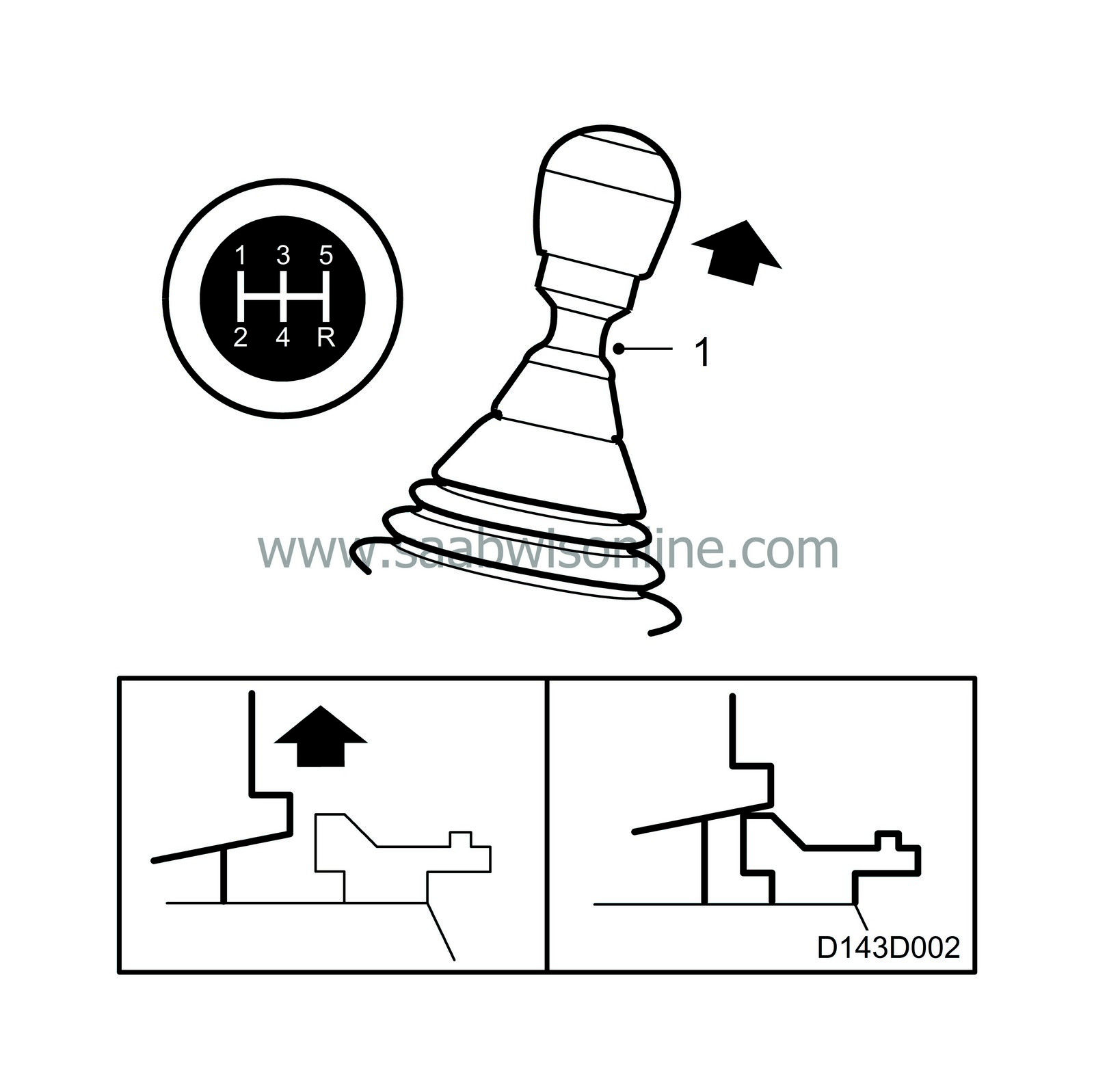
Gate positions are as shown on the gear lever knob.
In order to engage reverse (R), a latch collar under the lever knob must be lifted (1). In the neutral position, the spring-loading inside the gearbox causes the gear lever to attempt to maintain an equilibrium position between 3rd and 4th gears. This is to make it easy for the driver to find his way around the gear layout and avoid engaging the wrong gear.
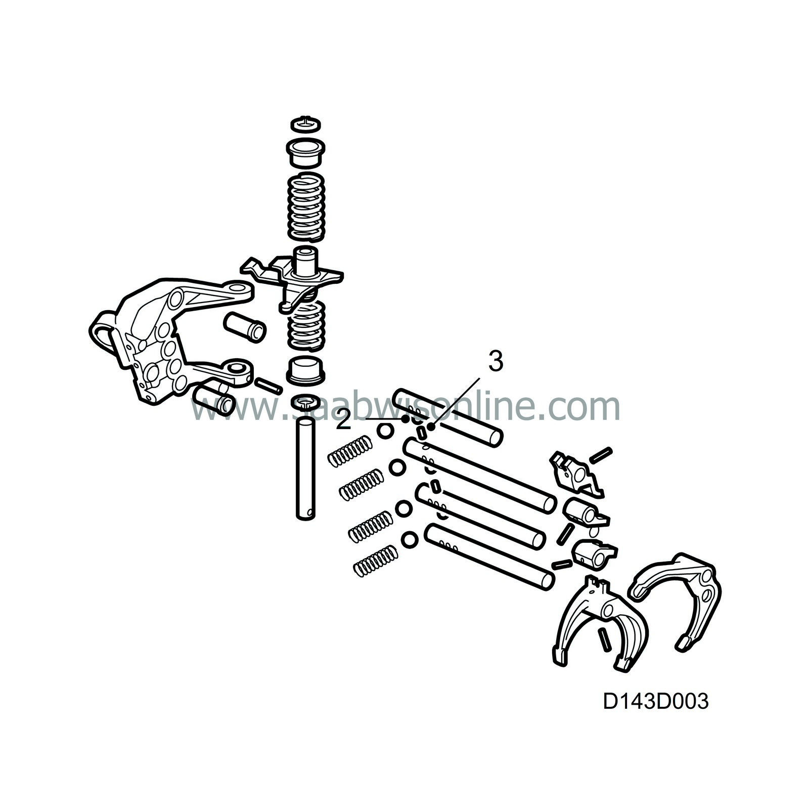
The selector shafts of all forward gears are mounted in PTFE bushes for minimum friction and to achieve low gear changing force with a perfect feel.

In order to prevent more than one gear being engaged at a time, the gearbox has a dual position detent mechanism. This detent mechanism primarily consists of 3 balls (2) and 2 cylindrical pins (3) which are aligned ball-pin-ball... through the bearing brackets and selector shafts. When a gear is engaged, a corresponding selector shaft is pushed in or out, breaking the alignment between balls and pins. The balls then assume the positions where they lock other selector shafts.

|
2.
|
Rubber universal joint
|
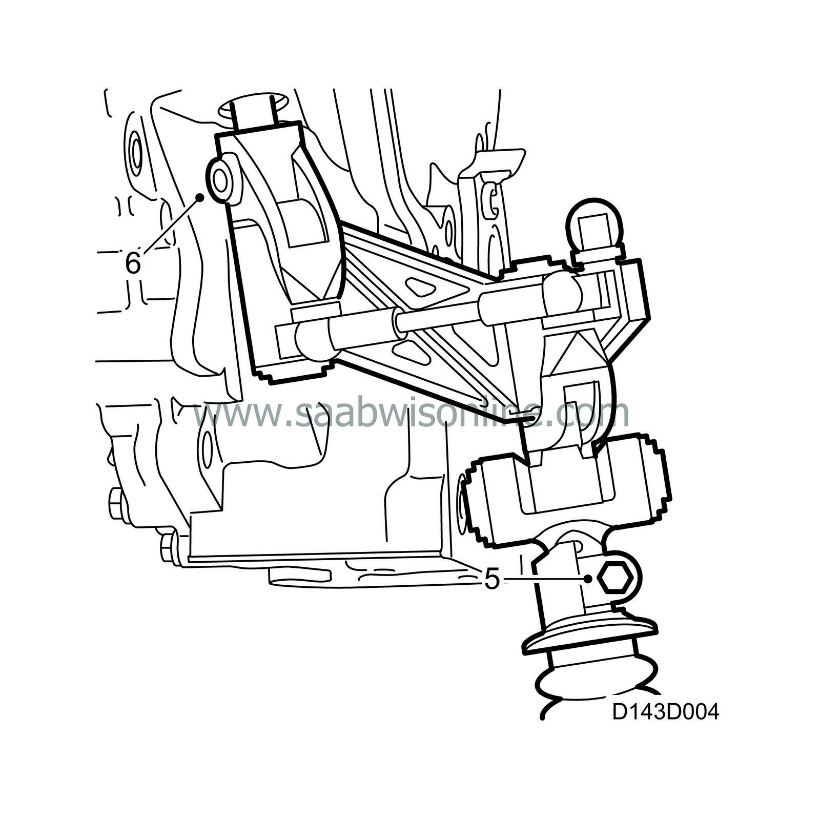
 Between the selector shaft (1) in the gearbox and the "rubber universal joint" (2) is a linkage that transfers torsional and shear forces from the gear lever to the selector shaft. The selector rod lever (3) is mounted via a link in a bracket in the rear engine mounting. The plastic link (4) is axially linked to the selector rod and radially mounted in the selector rod lever. The plastic link transfers the tensile and shear forces from the selector rod to the selector shaft in which it is axially mounted. The lever is fixed to, and transfers the selector rod's torsional forces via, the parallel link (5) to the lever which is fixed to the selector shaft and axially mounted in the plastic link.
In order to prevent the propagation of noise and vibration from the engine via the selector rod (6), the linkage between the selector shaft in the gearbox and the external selector mechanism is equipped with a rubber universal joint.

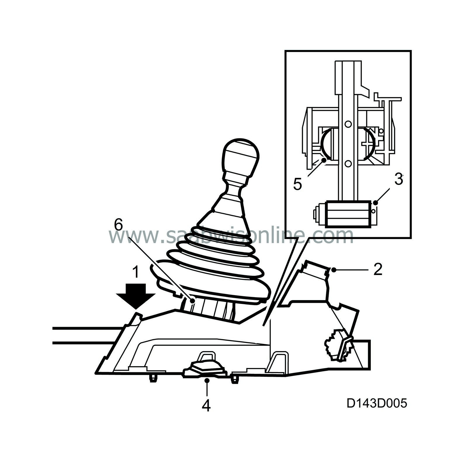
The external selector mechanism (selector rod) can be locked in 4th gear in the gear-lever housing by inserting a locking pin through the hole (1) in the gear-lever housing. With 4th gear engaged, the selector shaft in the gearbox can also be locked with a locking pin and connected to the selector rod with the clamp in the linkage. This provides a precise, "service-friendly" method of fitting and adjusting between the external selector mechanism and the gearbox.
The car is equipped with a gear lever lock. This means that the gear lever is locked in reverse when the ignition switch (2) is set to LOCK. The gear lever (3) is secured by a lock plate (4) which is controlled by the ignition switch.
The gear lever ball (5) is mounted in a self-adjusting ball socket (6) to avoid play.


