Bus communication
| Bus communication |
| • |
ACC control module (216)
|
|
| • |
Radio connector C (267c)
|
|
| • |
Airbag/SRS control module (331)
|
|
| • |
Radio (353)
|
|
| • |
CD changer (355)
|
|
| • |
PSM control module (357Dk)
|
|
| • |
Control module, TRIONIC (430)
|
|
| • |
TCM control module (502)
|
|
| • |
M2.10.3 control module (505)
|
|
| • |
MIU (540)
|
|
| • |
SID (541)
|
|
| • |
ABS control module (547)
|
|
| • |
STC control module (565)
|
|
| • |
Trionic OBDII control module (589)
|
|
| • |
EDC 15 control module (595)
|
|
| • |
Auxiliary heater control module (597)
|
|
| • |
Diesel pump (598)
|
|
| • |
DICE control module (628)
|
|
| • |
TWICE control module (632)
|
|
| P bus and I bus |

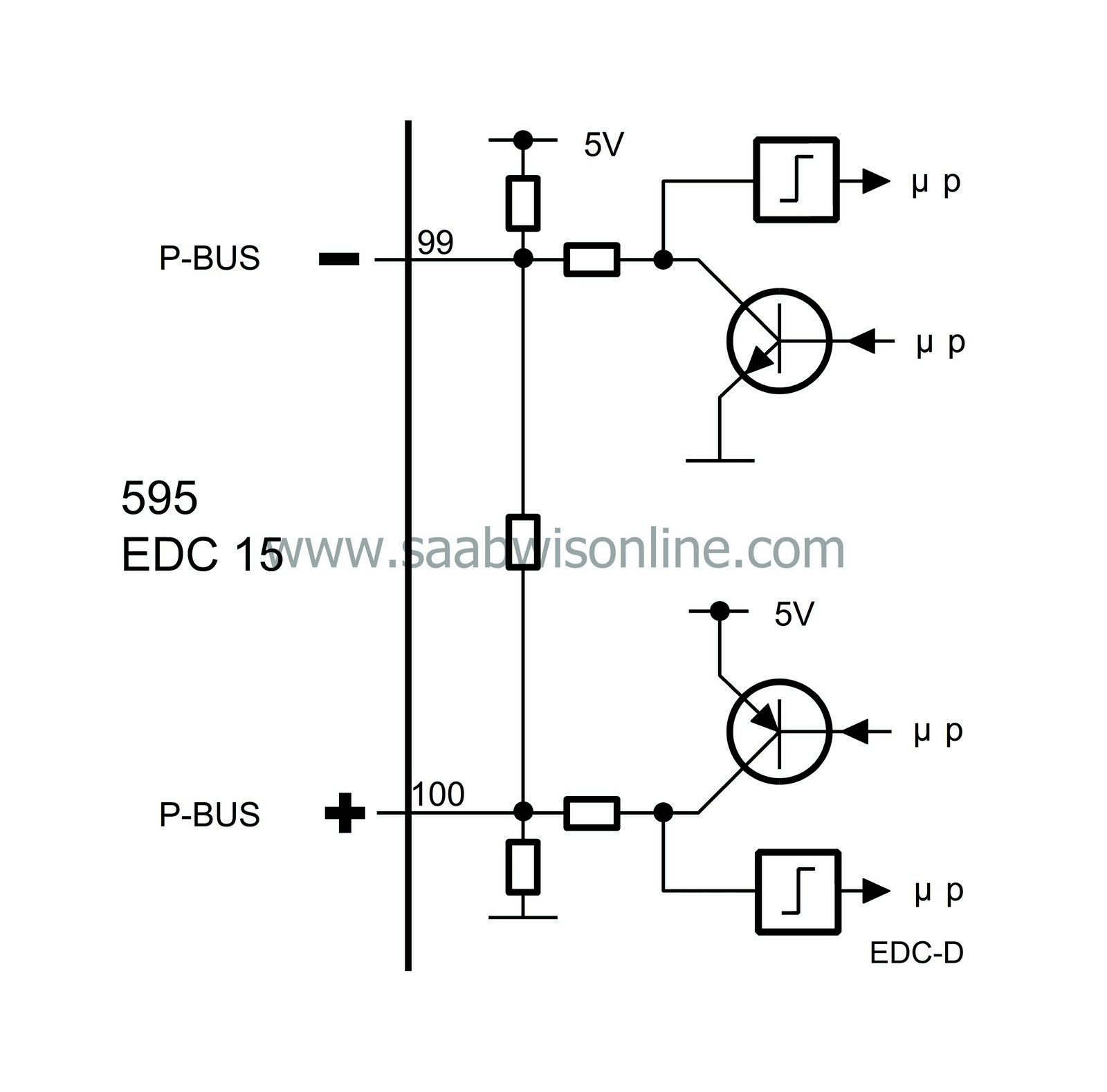
A bus is understood to be the leads over which information is sent digitally and serially. Digital means that the voltage difference between the leads has only two values, roughly 0 V and 5 V. The information is coded so that different combinations of 0 V and 5 V pulses have different meanings.
Serial means that the information is sent in ”packets” which are transmitted one after the other in rapid succession.
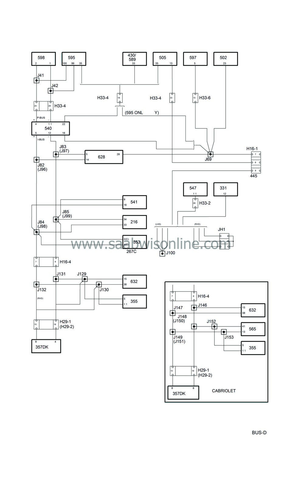
Half of the control modules in the Saab 9-3 are connected to the bus.
The buses consist of a P bus (Powertrain Bus) and an I bus (Instrument Bus). Both buses are connected to the MIU (Main Instrument Unit). The buses are electrically isolated from each other.
The diagnostic tool is not connected directly to the bus but communicates via the DICE, one of the control modules connected to the I bus, and so has access to all control modules connected to the bus. The EDC 15 control module, however, is connected directly to the K-lead for diagnostic communication.
The data transfer rate of the P bus is ten times faster than that of the I bus. The reason for this is that the powertrain systems need information with the least possible delay.
All information sent out by a control module is available to all other control modules connected to the bus. The MIU ensures that the information which is available on one bus is also available on the other.
The control modules send out information on the bus at regular intervals. The time between two transmissions depends on what information is being transmitted and varies between 10 milliseconds (0.010 seconds) and 1 second. Information is also transmitted by the control module whenever the information changes.
The transfer of information between the control modules takes place on two leads, bus+ (green lead) and bus- (white lead). The two leads are twisted to reduce sensitivity to electrical interference.
| Diagnostics |
In a bus system, all units must be able to communicate with each other. For example, the engine cannot be started unless the EDC 15 can receive the immobilization information sent out by TWICE.
Bus faults
All communication between the diagnostic tool and systems connected to the bus takes place through DICE. Irrespective of which system is contacted, the diagnostic tool first checks by means of DICE that all on-board systems connected to the bus, except for the diesel pump, are turned on and are communicating. If any control module connected to the bus, except for the diesel pump, is missing, the diagnostic tool will show this. This means that all control modules connected to the bus, except for the diesel pump, are communicating properly unless the diagnostic tool warns otherwise.EDC 15 and the diesel pump monitor P-bus communication and a diagnostic trouble code is generated if a fault should occur, see
 .
.
| The EDC 15 control module sends the following information: |
| EDC 15 sends | Values | Used by | Value dependent on the following sensor input, signal or function |
|
CHECK ENGINE Lamp
|
ON/OFF
|
MIU
|
Internal diagnostics
|
|
CRUISE Lamp
|
ON/OFF
|
MIU
|
Cruise control function
|
|
Fuel Consumed
|
0-65535 ml
|
MIU
|
Fuel injection function
|
|
Engine Running
|
ON/OFF
|
ACC, DICE, SID
|
Crankshaft position sensor
|
|
Engine speed
|
0-6000 rpm
|
MIU, ACC, Diesel pump
|
Crankshaft position sensor
|
|
Coolant temperature
|
-50 -200 °C
|
MIU, DICE, ACC
|
Engine coolant temperature sensor
|
|
Glow indicator lamp
|
ON/OFF
|
MIU
|
Glow function
|
|
Fuel mass / Combustion Requested
|
0-100 mg/c
|
Diesel pump
|
Fuel injection function
|
|
Start of pressure build-up Requested (Crankshaft angle)
|
-10 - 40 degrees
|
Diesel pump
|
Fuel injection function
|
|
Start of pressure build-up Requested (Pump shaft angle)
|
0 - 20 degrees
|
Diesel pump
|
Fuel injection function
|
|
Immobilizer
|
Code
|
TWICE
|
Immobilizer function
|
|
Diagnostic communication
|
--
|
Diesel pump
|
Control module powered and bus leads intact.
|
| The EDC 15 control module uses the following information: |
| EDC 15 receives | Values | Sent by | Value dependent on the following sensor input, signal or function |
|
A/C
|
ON/OFF
|
DICE
|
A/C (bus from ACC), engine coolant temperature (bus from EDC 15), A/C pressure and evaporator temperature
|
|
A/C pressure
|
0 -30 bar
|
DICE
|
A/C pressure sensor
|
|
Immobilizer
|
Code
|
TWICE
|
Immobilizer function
|
|
Pump rpm
|
0-3000 rpm
|
Diesel pump
|
Pump shaft sensor
|
|
Latest injection duration (Pump shaft angle)
|
0 - 90 degrees
|
Diesel pump
|
The length of time during which the pump control module has kept the needle valve for the flow control closed at the latest injection
|
|
Fuel temperature
|
-50 -200 °C
|
Diesel pump
|
Fuel temperature sensor
|
|
Diagnostic communication
|
--
|
Diesel pump
|
Control module powered and bus leads intact.
|
| The diesel pump sends the following information: |
| Diesel pump sends | Values | Used by | Value dependent on the following sensor input, signal or function |
|
Pump rpm
|
0-3000 rpm
|
EDC 15
|
Pump shaft sensor
|
|
Latest injection duration (Pump shaft angle)
|
0 - 90 degrees
|
EDC 15
|
The length of time during which the pump control module has kept the needle valve for the flow control closed at the latest injection
|
|
Fuel temperature
|
-50 -200 °C
|
EDC 15
|
Fuel temperature sensor
|
|
Diagnostic communication
|
--
|
EDC 15
|
Control module powered and bus leads intact.
|
| The diesel pump uses the following information: |
| Diesel pump receives | Values | Sent by | Value dependent on the following sensor input, signal or function |
|
Engine speed
|
0-6000 rpm
|
EDC 15
|
Crankshaft position sensor
|
|
Fuel mass / Combustion Requested
|
0-100 mg/c
|
EDC 15
|
Fuel injection function
|
|
Start of pressure build-up Requested (Crankshaft angle)
|
-10 - 40 degrees
|
EDC 15
|
Fuel injection function
|
|
Start of pressure build-up Requested (Pump shaft angle)
|
0 - 20 degrees
|
EDC 15
|
Fuel injection function
|
|
Diagnostic communication
|
--
|
EDC 15
|
Control module powered and bus leads intact.
|


