Evaporative emission system
| Evaporative emission system |

Evaporative emission canister
The evaporative emission canister is filled with active carbon, which "stores" the fuel vapour coming from the tank until it is exposed of through the purge valve into the intake manifold and used during combustion.Consequently, the evaporative emission canister is connected to the fuel tank and the intake manifold with hoses but is also in contact with the surrounding air. Air is drawn into the evaporative emission canister through this air connection and sent to the intake manifold, taking with it the fuel vapour in the canister.
EVAP canister purge valve
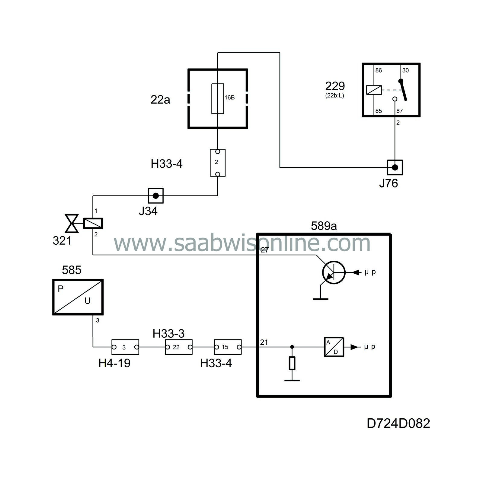
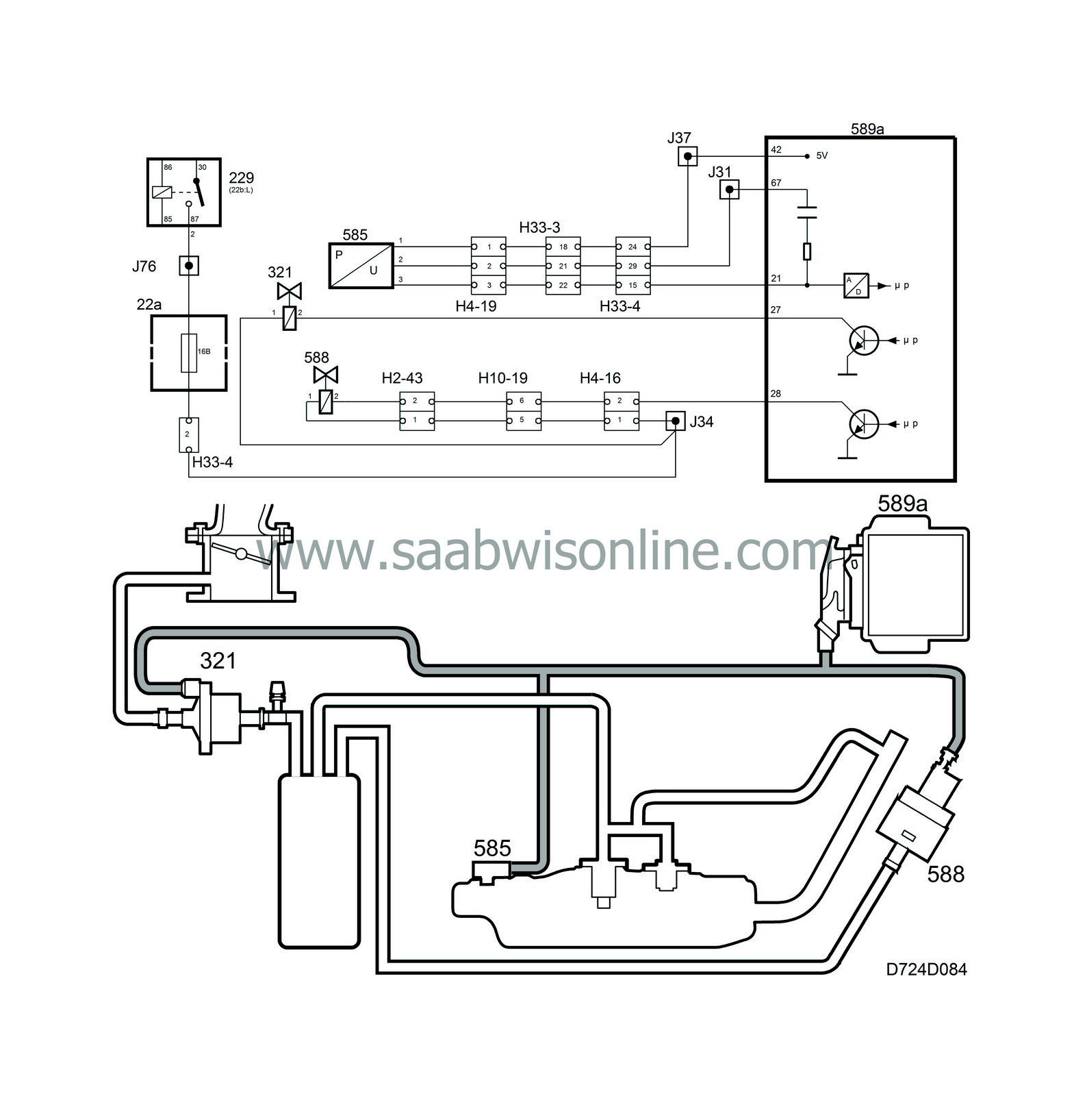
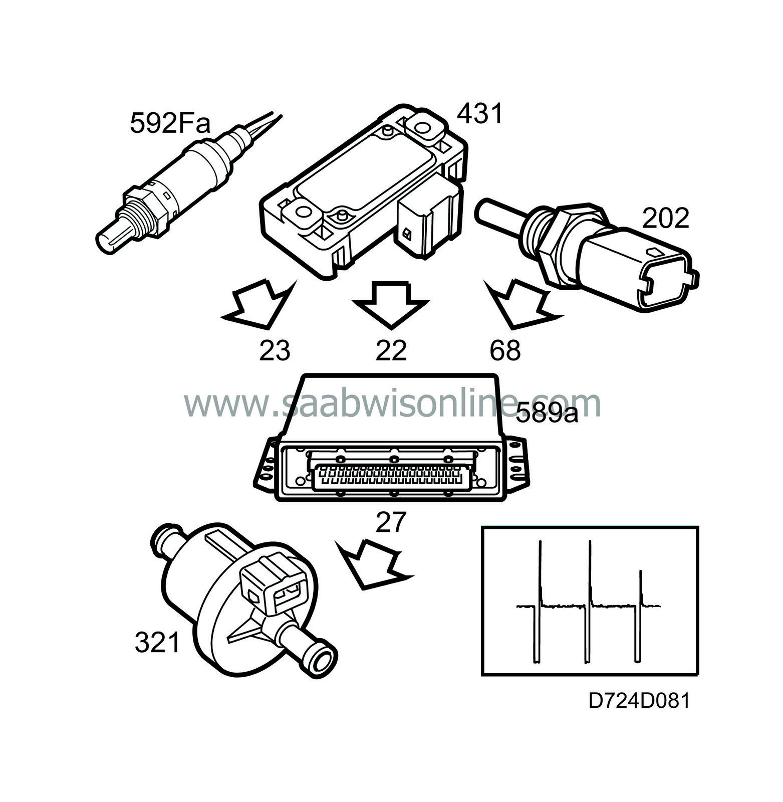
The purge valve is a solenoid valve located in the vacuum hose between the evaporative emission canister and the intake manifold after the throttle.The valve is powered from the main relay and is controlled from control module pin 27. On cars without tank integrity diagnostics, the lead is coupled together with control module pin 21. By measuring the voltage on pin 21, the control module can determine whether the function is working electrically.
The valve is supplied with an 8 Hz PWM and starts to work as soon as closed loop is activated, the coolant temperature is above 60C (140F) and the intake manifold pressure is below 90 kPa.
The control module initiates the purge with very short ground impulses, the length of which is gradually increased. This is because closed loop must have time to compensate for the addition of fuel. The valve works for 4 1/2 minutes, pauses for 1/2 minute and then works for another 4 1/2 minutes and so on.
| Diagnosis |
EVAP canister purge valve
| • |
There is no diagnosis for the electric circuit to the EVAP canister purge valve. If there is a break in the circuit, diagnostic trouble code P0455 will be generated to indicate a major leak.
|
|
| Tank integrity diagnosis |

Pressure sensor
A check that no leakage occurs in the evaporative emission system can be carried out by means of a tank integrity diagnosis. The leakage test involves creating a partial vacuum in the system and maintaining it for a given time during the diagnostic process.The diagnostics logic has been improved to provide more reliable diagnosis. A diagnostic trouble code will not be set until a negative result has been obtained from two tests during the same driving cycle.
If there is leakage during one of the tests, SID will display the message ”TIGHTEN FUEL FILLER CAP”. This message is sent after each test if leakage is detected, but not more than twice in succession. After this, it is not possible to send the message again until the diagnosis from a test has reported OK.
A differential pressure sensor is mounted on the tank filler pipe. This pressure sensor is connected to the filler pipe with a short hose and is powered with 5 V from control module pin 42. It is grounded from control module pin 67.
The pressure sensor delivers a voltage to control module pin 21 that is proportional to the difference between the pressure in the tank and atmospheric pressure.
If there is no difference in pressure, the voltage from the pressure sensor will be approx. 2.5 V. The pressure sensor is used only for OBD II diagnostics.
Close valve
The close valve is mounted by the EVAP canister. It is connected to the canister air inlet and is powered from the main relay. The valve is grounded from control module pin 28.The valve is normally open.
With the engine running, the valve will only close when the tank integrity check is in progress. The close valve is used only for OBD II diagnostics.
| Diagnosis |
Pressure sensor
| • |
If the sensor voltage is too low, diagnostic trouble code P0452 will be generated.
|
|
| • |
If the sensor voltage is too high, diagnostic trouble code P0453 will be generated.
|
|
Close valve
| • |
There is no diagnosis for the electric circuit to the close valve. If there is a break in the circuit, P0455 will be generated to indicate a major leak.
|
|


