
Test readings, control module connections
| Test readings, control module connections |
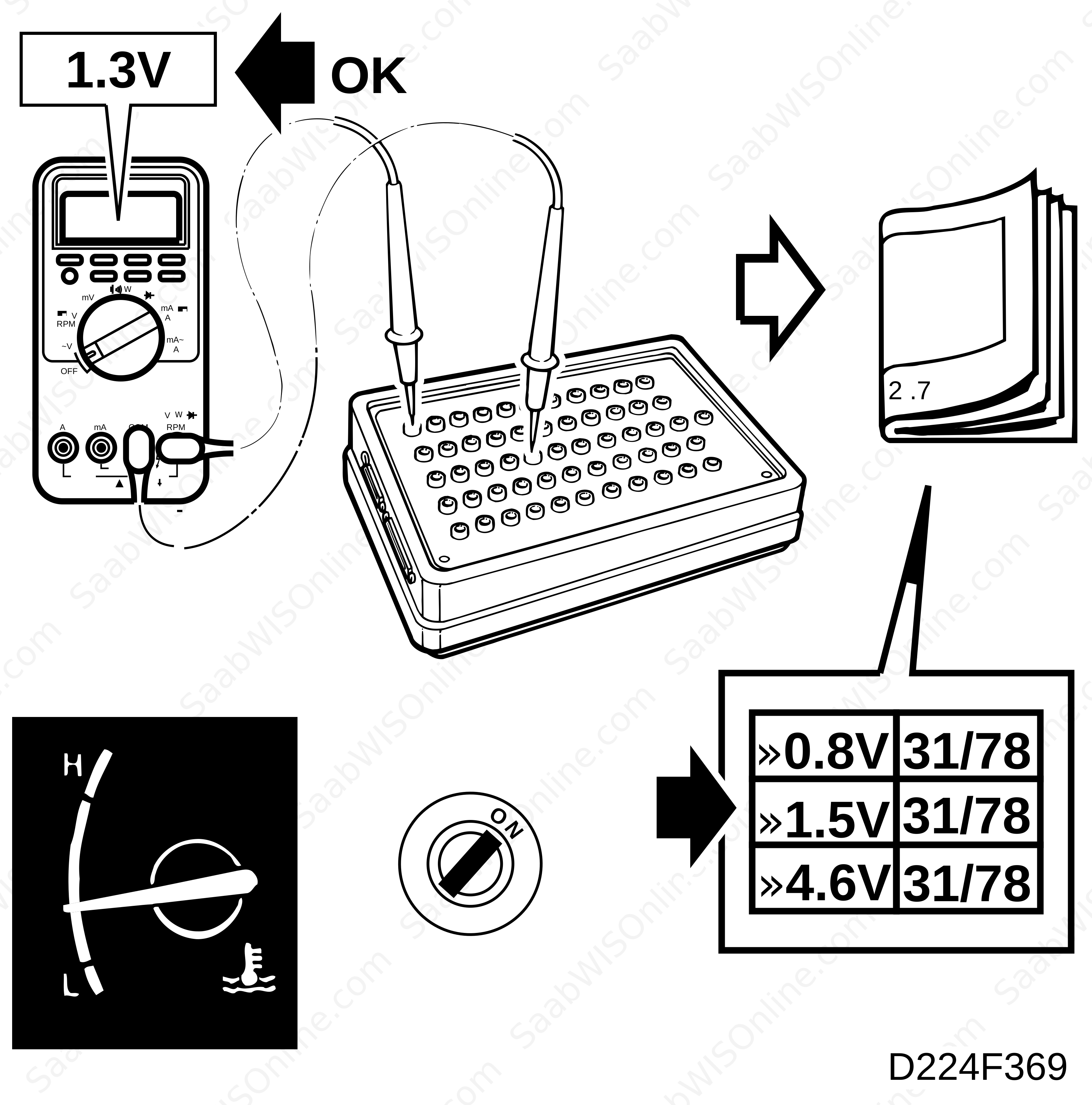
| Scope |
The following pages contain readings and directions for measuring signals/levels on the Trionic control module.
| Keep in mind: |
| • |
Note the measuring conditions, use common sense when considering the measurement results.
|
|
| • |
The specified values are with the ignition in the ON position unless otherwise stated.
|
|
| • |
First, check that the control module is supplied with power and that it is grounded.
|
|
| • |
Then check all the inputs and signals from other systems.
|
|
| • |
Finally, check the control module outputs. Remember that the test readings do not indicate whether the actuator is working.
|
|
| • |
If any measured value is incorrect, use the wiring diagram to diagnose which leads, connections or components that should be checked further.
|
|
| • |
Specified values refer to calibrated Fluke 88/97.
|
|
| • |
The measured values %(+) and ms(+) indicate the pulse ratio and pulse length of the signal respectively. A test instrument with pulse ratio respective pulse width measuring capacity must be used. The sign indicates positive trigger pulse, TRIG+.
|
|
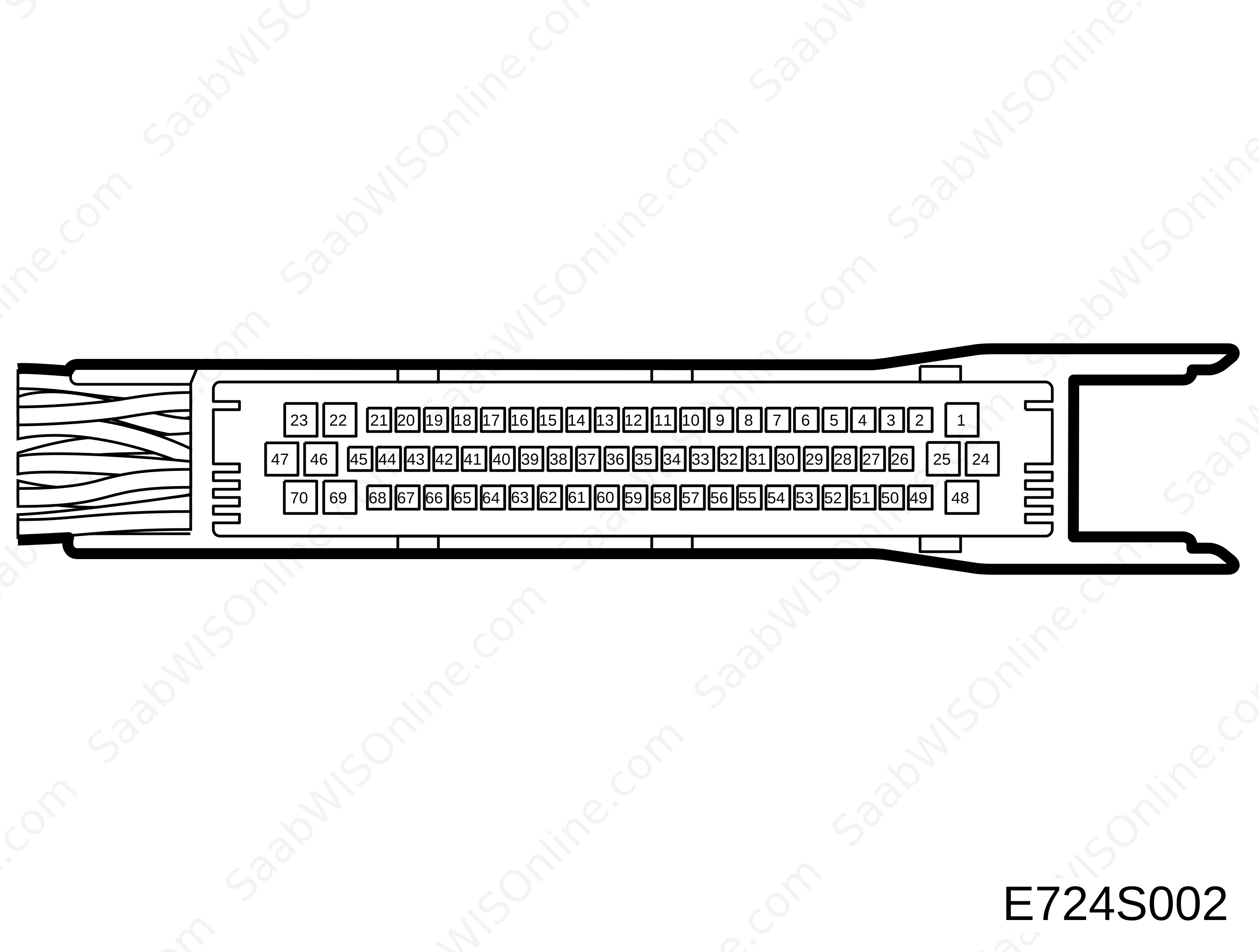
> = greater than ; < = less than ; ∼ = alternating current. Pins without further comments have no connections. (LP: LOGIC PROBE P=select pulse; p=visible pulses).
|
Pin
|
Colour
|
Component/Function
|
In/Out
|
Test conditions
|
Across + -
|
Value
|
|
1
|
PK/WH
|
+30
|
in
|
Idling speed
|
B+ to 1
|
<0.5 V
|
|
2
|
GN/BK
|
Boost pressure control valve
|
out
|
Idling speed
|
2 - 25
|
90 Hz 17.5 % (-) 1.9 ms (-) (LP HI LO)
|
|
3
|
GN/WH
|
Injector 1
|
out
|
Idling speed
|
3 - 25
|
7.5 Hz 2.5-4.5 ms (-) (LP
HI LOp)
|
|
4
|
GN/WH
|
Injector 2
|
out
|
Idling speed
|
4 - 25
|
7.5 Hz 2.5-4.5 ms (-) (LP
HI LOp)
|
|
5
|
VT/WH
|
Injector 3
|
out
|
Idling speed
|
5 - 25
|
7.5 Hz 2.5-4.5 ms (-) (LP
HI LOp)
|
|
6
|
GY/WH
|
Injector 4
|
out
|
Idling speed
|
6 - 25
|
7.5 Hz 2.5-4.5 ms (-) (LP
HI LOp)
|
|
9
|
OG/BK
|
Trigger 1
|
out
|
Idling speed
|
9 - 25
|
7.5 Hz 8.3 % (-) 11 ms (-) (LP
HI LOp)
|
|
10
|
GN/YE
|
Trigger 2
|
out
|
Idling speed
|
10 - 25
|
7.5 Hz 8.3 % (-) 11 ms (-) (LP
HI LOp)
|
|
11
|
BU/RD
|
Trigger 3
|
out
|
Idling speed
|
11 - 25
|
7.5 Hz 8.3 % (-) 11 ms (-) (LP
HI LOp)
|
|
12
|
GY/RD
|
Trigger 4
|
out
|
Idling speed
|
12 - 25
|
7.5 Hz 8.3 % (-) 11 ms (-) (LP
HI LOp)
|
|
13
|
OG/WH
|
Engine torque limitation
|
in
|
|
13 - 25
|
B+
|
|
Gear
|
13 - 25
|
0 V
|
||||
|
14
|
BK/WH
|
DRIVE
|
in
|
P, N
|
14 - 25
|
0 V
|
|
R, D, 1, 2, 3
|
14 - 25
|
B+
|
||||
|
15
|
VT
|
Brake light switch
|
in
|
brake pedal not depressed
|
15 - 25
|
0 V
|
|
brake pedal depressed
|
15 - 25
|
B+
|
||||
|
17
|
YE/BN
|
Combustion cyl. 1+2
|
in
|
Idling speed
|
17 - 25
|
15-30 Hz (LP
LO HIp)
|
|
18
|
BN/RD
|
Combustion cyl. 3+4
|
in
|
Idling speed
|
18 - 25
|
15-30 Hz (LP
LO HIp)
|
|
20
|
PK
|
Manifold absolute pressure signal
|
out
|
|
20 - 67
|
1.0 V (A somewhat lower reading may be obtained at high altitude.)
|
|
22
|
BU/BN
|
Manifold absolute pressure sensor
|
in
|
|
22 - 67
|
100 kPa= 1.9 V see also tech. data
|
|
23
|
GN
|
Oxygen sensor 1
|
in
|
Idling, warm engine and >1 min. since start
|
23 - 47
|
0.1-0.9 V
|
|
24
|
BK
|
Main ground
|
in
|
Idling speed
|
24 - B-
|
<0.1 V
|
|
25
|
BK
|
Main ground
|
in
|
Idling speed
|
25 - B-
|
<0.1 V
|
|
26
|
BU
|
Boost pressure control valve
|
out
|
1000-1500 rpm
|
26-25
|
90 Hz 17.5 % (-) 1.9 ms (-) (LP P HI LO)
|
|
27
|
YE/GY
|
EVAP canister purge valve
|
out
|
Idling with warm engine
|
27 - 25
|
1.3 V 8 Hz 10 % (-) 12 ms (-) (
HI
LOp)
|
|
28
|
GN
|
EVAP canister close valve
|
out
|
|
28 - 25
|
B+
|
|
Activate with Tech 2
|
28 - 25
|
0 V
|
||||
|
31
|
BU/GY
|
Main relay
|
out
|
|
31 - 25
|
B+
|
|
start the engine
|
31 - 25
|
<0.5 V
|
||||
|
32
|
YE/GN
|
CHECK ENGINE
|
out
|
|
32 - 25
|
<0.5 V
|
|
engine running and CHECK ENGINE lamp off
|
32 - 25
|
B+
|
||||
|
33
|
GY/BK
|
Diagnosis
|
in/out
|
33 - 25
|
B+
|
|
|
36
|
BU/WH
|
Cruise Control
|
in
|
|
36 - 25
|
approx. 10 V
|
|
CC engaged
|
36 - 25
|
<0.5 V
|
||||
|
39
|
PK/BK
|
Speed signal
|
in
|
lift front right wheel, rotate wheel 1/2 rps
|
39 - 25
|
15 Hz 50 % (LP HIp LOp)
|
|
41
|
YE
|
Crankshaft position sensor
|
in
|
Idling speed
|
41 - 67
|
5-10 V∼ approx. 870 Hz (LP HI LO)
|
|
42
|
WH/BK
|
Throttle position sensor
|
out
|
|
42 - 67
|
5 V
|
|
43
|
GY
|
Pressure sensor
|
out
|
|
43 - 67
|
5 V
|
|
44
|
OG
|
Knock signal
|
in
|
Idling speed
|
44 - 25
|
50-100 mV∼ (LP P LO)
|
|
45
|
GN/BN
|
Throttle position sensor
|
in
|
|
45 - 67
|
idle. approx 0.5 V see also tech. data
|
|
46
|
WH/BK
|
Intake air temperature sensor
|
in
|
40C (104F)
|
46 - 67
|
1.5 V see also tech. data
|
|
47
|
BN/WH
|
Oxygen sensor, reference ground
|
in
|
Idling speed
|
47 - 67
|
0-1 V
|
|
48
|
PK/WH
|
+30
|
in
|
Idling speed
|
B+ - 48
|
<0.5 V
|
|
49
|
BU/VT
|
Idle air control valve
|
out
|
A/C and all electric consumers off
|
49 - 25
|
500 Hz 25-50 % 0.5-1.0 ms (LP HI LO)
|
|
50
|
BK/WH
|
Oxygen sensor 1, pre-heating
|
out
|
Idling speed
|
50 - 25
|
approx. 0.5 V
|
|
remove fuse no. 38
|
50 - 25
|
0 V
|
||||
|
52
|
YE/WH
|
Vacuum pump, brake system
|
out
|
P, N
|
52 - 25
|
B+
|
|
R, D, 1, 2, 3
|
52 - 25
|
<0.5 V
|
||||
|
54
|
RD/WH
|
A/C out
|
out
|
Idling, A/C ON
|
54 - 25
|
<0.5 V
|
|
Idling, A/C OFF
|
54 - 25
|
B+
|
||||
|
56
|
WH
|
Fuel pump relay
|
out
|
|
56 - 25
|
B+
|
|
Idling speed
|
56 - 25
|
<0.5 V
|
||||
|
57
|
GN/OG
|
Throttle position signal
|
out
|
Idling speed
|
57 - 25
|
100 Hz 9 % (+) 0.9 ms (+) (LP
LO HI)
|
|
58
|
GN/RD
|
Engine speed signal
|
out
|
Idling speed
|
58 - 25
|
30 Hz (LP
LO HIp)
|
|
59
|
GN/GY
|
A/C in
|
in
|
Idling, A/C ON
|
59 - 25
|
B+
|
|
Idling, A/C OFF
|
59 - 25
|
0 V
|
||||
|
60
|
YE/GY
|
+15
|
in
|
|
B+ - 60
|
<0.5 V
|
|
62
|
RD/BK
|
For production only
|
|
|
|
|
|
63
|
BN
|
For production only
|
|
|
|
|
|
65
|
YE
|
For production only
|
|
|
|
|
|
66
|
BK
|
Reference ground, engine coolant temperature sensor
|
in
|
|
66 - 25
|
<0.05 V
|
|
67
|
BK
|
Sensor ground
|
out
|
|
67 - 25
|
<0.05 V
|
|
68
|
YE/WH
|
Engine coolant temperature sensor
|
in
|
90C (194F)
|
68 - 66
|
0.41 V see also tech. data
|
This project is supported by memberships and donations. If you use this site, please consider Joining SCNA and/or making a donation.
Our Friends