Checking and adjusting basic charging pressure (B235R)
|
|
Checking and adjusting basic charging pressure (B235R)
|
|
1.
|
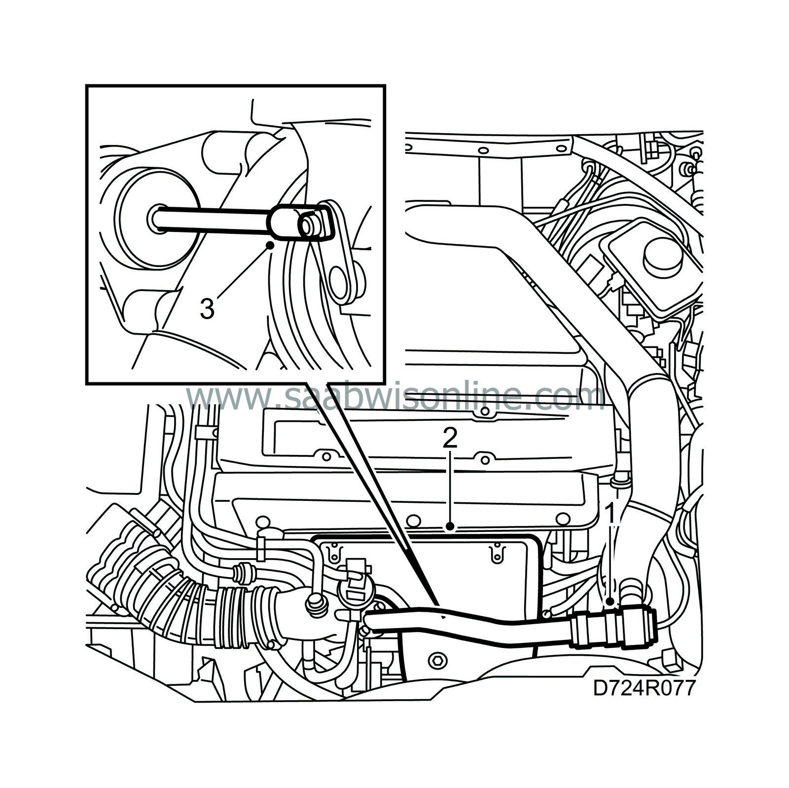
Remove the bypass pipe with valve.

|
Note
|
|
There is an O-ring where the bypass pipe is fastened to the turbocharger inlet pipe.
|
|
|
2.
|
Remove the exhaust manifold heat shield. The heat shield is fastened with a nut and two clips underneath.
|
|
3.
|
Remove the locking clip on the operating arm with circlip pliers, part no. 83 94 538.
|
|
4.
|
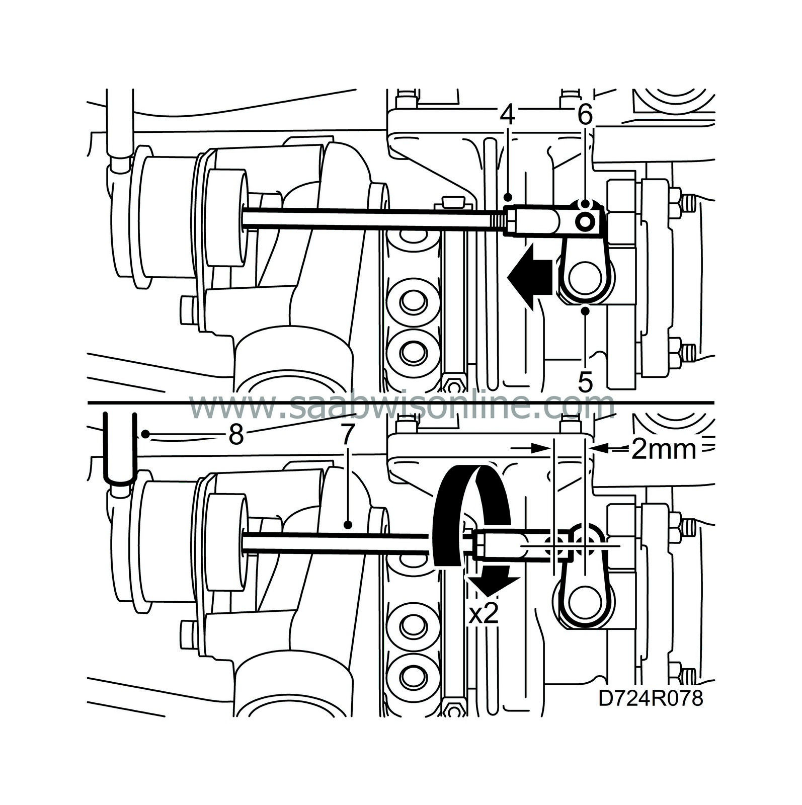
Grip the pushrod with pliers, part no. 83 94 066 or similar tool. Undo the lock nut with spanner, part no. 83 94 520 or equivalent.

|
|
5.
|
Hold the operating arm and detach the pushrod. Secure the arm. Otherwise, the operating arm may ”jump over”.
|
|
6.
|
Move the operating arm on the boost pressure control valve towards ”Closed” and adjust the end piece so that the pushrod fits easily on the operating arm pin.
|
|
7.
|
Detach the pushrod from the control arm pin. Turn the end piece clockwise approx. 2 turns so that a 2 mm tension is achieved. Hook on the pushrod to the operating arm pin. Fit the locking ring.
|
|
8.
|
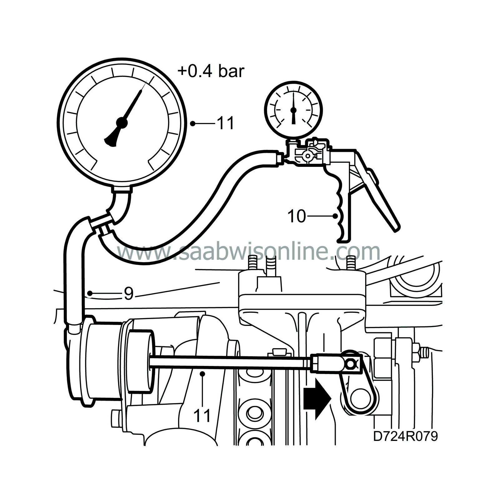
Detach the hose from the diaphragm box.
|
|
9.
|
Connect pressure/vacuum pump, part no. 30 14 883, to the diaphragm box and pressure gauge, part no. 83 93 514.

|
|
10.
|
Carefully pump up pressure until the control rod moves to regulate the boost pressure.
|
|
11.
|
Just as the control rod starts to move, read off the pressure on the pressure gauge. It should be 0.45 bar (±0.03 bar).
|
|
12.
|
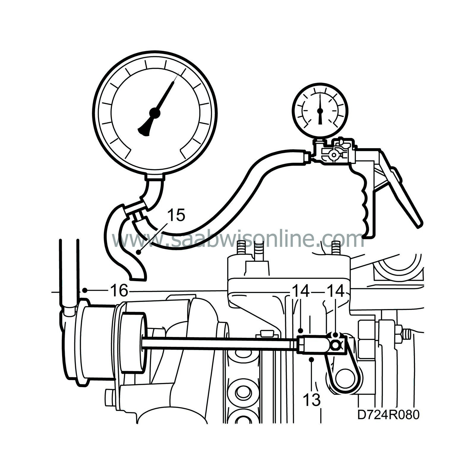
Shorten the rod if the pressure is too low until 0.45 bar is obtained.
|
|
13.
|
Undo the pushrod and apply Molykote 1000, part no. 30 20 971, or equivalent to the pin on the operating arm.

|
|
14.
|
Fit the pushrod and clip, grip the pushrod with a pair of adjustable pliers and lock the nut.
|
|
15.
|
Remove the pressure gauge and pump.
|
|
16.
|
Reconnect the hose to the diaphragm box.
|
|
17.
|
Fit the heat shield.

|
|
18.
|
Lubricate the O-ring with acid-free petroleum jelly and fit the bypass pipe.
Tightening torque: 8 Nm (5.9 lbf ft)
|


