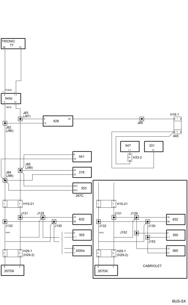
Bus communication, Trionic T7
| Bus communication, Trionic T7 |
| • |
Control module, ACC (216)
|
|
| • |
Radio switch C (267c)
|
|
| • |
Control module, airbag/SRS (331)
|
|
| • |
Radio (353)
|
|
| • |
CD changer (355)
|
|
| • |
Control module, PSM (357Dk)
|
|
| • |
Control module, Trionic T7 (430b)
|
|
| • |
MIU (540d)
|
|
| • |
SID (541)
|
|
| • |
Control module (ABS) 547
|
|
| • |
Control module STC (565)
|
|
| • |
Control module, Trionic T7 OBDII (589b)
|
|
| • |
Control module, DICE (628)
|
|
| • |
Control module, TWICE (632)
|
|
| P bus and I bus |


A bus is understood to be the leads over which information is sent digitally and serially. Digital means that the voltage difference between the leads has only two values, roughly 0 V and 5 V. The information is coded so that different combinations of 0 V and 5 V pulses have different meanings.
Serial means that the information is sent in ”packets” which are transmitted one after the other in rapid succession.
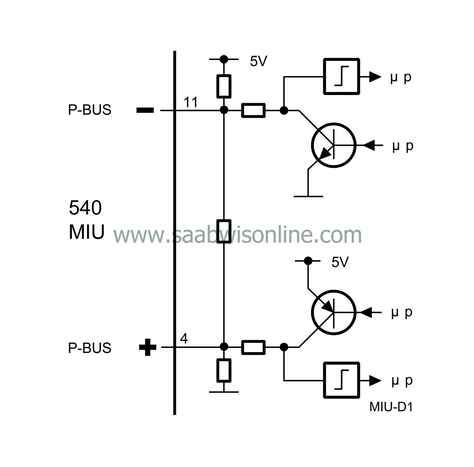
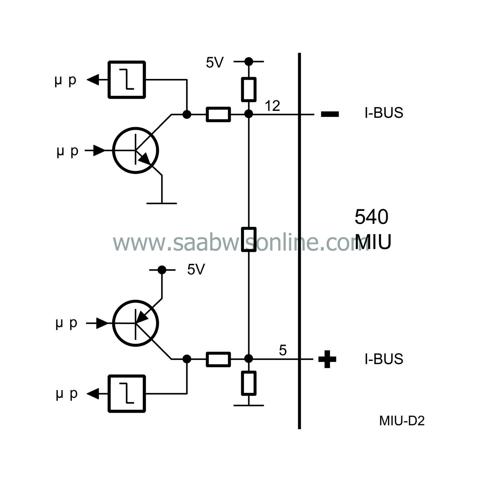
The bus is divided into the P-bus (Powertrain Bus) and the I-bus (Instrument Bus). Both buses are connected to the main instrument unit (MIU). The buses are electrically isolated from each other.
Only diesel-engined cars and cars with Trionic T7 have a P bus. Other petrol-engined variants have the same engine management system and automatic transmission as the earlier 900 model (T5, M2.10.3 and TCM) and these have no bus connections.
As in the 9-5, the Airbag and ABS control modules have no bus connections.
The diagnostics instrument is not directly connected to the bus but communicates via DICE, which is connected to the I-bus, and therefore has access to all the control modules connected to the bus.
The P-bus has a data transfer rate ten times higher than that of the I-bus. This is because the powertrain systems require information with the least possible delay.
All the information sent from one control module is accessible for all the other control modules on the bus. The MIU is responsible for making information on one bus available to the other bus.
The control modules send out information on the bus at regular intervals. The time between two transmissions depends on the information being transmitted and varies between 10 milliseconds (0.010 seconds) and 1 second. Information is also transmitted by the control modules whenever the information changes.
The transfer of information between control modules takes place on two leads, bus+ (green lead) and bus- (white lead). The leads are twisted to increase their resistance to electrical interference.
| The MIU uses the following information: |
| Information | Values | Off | The value depends on the following sensor input, signal or function |
|
LH direction indicators
|
ON/OFF
|
DICE
|
Control module activation of output to lamps
The MIU lights the indicator lamp for LH direction indicators. |
|
RH direction indicators
|
ON/OFF
|
DICE
|
Control module activation of output to lamps
The MIU lights the indicator lamp for RH direction indicators. |
|
Rear fog light
|
ON/OFF
|
DICE
|
Control module activation of output to fog light
The MIU lights the indicator lamp for the rear fog light. |
|
Driver's door
|
OPEN/CLOSED
|
TWICE
|
Door switch
The MIU lights the driver's door symbol. |
|
Passenger's door
|
OPEN/CLOSED
|
TWICE
|
Door switch
The MIU lights the passenger's door symbol. |
|
LH rear door
|
OPEN/CLOSED
|
TWICE
|
Door switch
The MIU lights the LH rear door symbol |
|
RH rear door
|
OPEN/CLOSED
|
TWICE
|
Door switch
The MIU lights the RH rear door symbol. |
|
Boot lid
|
OPEN/CLOSED
|
TWICE
|
Lid switch
The MIU lights the boot lid symbol. |
|
Steering wheel location
|
LHD/RHD
|
TWICE
|
Control module programming.
The MIU uses the information to indicate door open on the pictogram, driver door/passenger door. |
|
Info Disp Lamp
|
ON/OFF
|
SID
|
The MIU lights the Info Display indicator lamp in the event of a text message.
|
|
Rheostat level
|
0-100 %
|
SID
|
Rheostat control module input
The MIU uses information on the rheostat setting to control the brightness of the instrument lighting. |
|
Rheostat Night Panel
|
0-100 %
|
SID
|
Rheostat control module input reduced by a fixed value.
|
|
Night Panel
|
ON/OFF
|
SID
|
The MIU turns off the lighting of certain instruments and displays.
|
|
Display lighting
|
0-100 %
|
SID
|
The MIU uses the information to control the display lighting.
|
|
Light intensity in cabin
|
Lux
|
SID
|
The MIU uses the information to control the brightness of indicator lamps.
|
|
Check Engine lamp
|
ON/OFF
|
T7
|
Internal diagnosis
|
|
SHIFT UP lamp
|
ON/OFF
|
T7
|
Wheel speed front right (lead from ABS)
|
|
CRUISE Lamp
|
ON/OFF
|
T7
|
Cruise Control function
|
|
TURBO gauge
|
0-255, no unit
|
T7
|
Current air mass per combustion
|
|
Fuel Consumed Since Start
|
0-65535 ml
|
T7
|
Fuel injection function
|
|
Engine speed
|
0-7000 rpm
|
T7
|
Crankshaft position sensor
|
|
Coolant temperature
|
-40–215°C
|
T7
|
Coolant temperature sensor
|
| The MIU sends the following information: |
| Information | Values | Used by | The value depends on the following sensor input, signal or function |
|
Vehicle speed
|
km/h (mph)
|
DICE, SID, ACC, Audio, TWICE, STC, T7
|
Wheel speed, RL (lead from ABS). The MIU controls the speedometer
|
|
A/C relay
|
ON/OFF
|
DICE
|
The MIU receives information via a lead to Trionic/Motronic. When the A/C relay is active, the MIU sends this information out on the bus.
|
|
Acoustic warning
|
Acoustic information
|
SID
|
Request for acoustic signal when central warning lamp or Info Displ goes on.
|
|
Tighten fuel filler cap
|
ON/OFF
|
SID
|
If there is a fault in the tank venting system, the MIU is informed on the bus from Trionic T7. The main instrument unit sends the information "Tighten fuel filler cap" on the bus. The message is displayed on the SID. OBDII only.
|
|
Fuel Consumed Since Start
|
0-65535 ml
|
SID
|
Bus from Trionic T7. The reading is corrected by an adjustment factor in the MIU. The factor can be adjusted with the diagnostics instrument.
|
|
Fuel level
|
litres
|
SID
|
Tank sensor, control module adjustment
The MIU sends information on the current amount of fuel in the tank. |
|
Odometer reading
|
km, miles
|
SID
|
Display value.
Information on distance driven. |
|
Identification number
|
---
|
TWICE
|
The number is generated in the MIU when the immobilization code is programmed in TWICE.
|
|
Diagnostics communication
|
---
|
DICE/
Diagnostic tool |
Control module should be live and the bus leads intact.
|


