
Test readings, control module connections
| Test readings, control module connections |

| Scope |
This section contains the readings and instructions for measuring voltage levels on the SID unit.
| Remember |
| • |
Note the test conditions and use common sense when assessing the test result.
|
|
| • |
The presented readings are with the ignition ON unless otherwise stated.
|
|
| • |
First check that the control module has a power supply and is grounded.
|
|
| • |
Then check all sensor inputs and signals from other systems.
|
|
| • |
Finally, check the control module outputs. Remember that the test readings do not indicate whether or not the actuator is in working order.
|
|
| • |
If any reading is not OK, consult the wiring diagram to trace the leads, connectors or components which should be checked more thoroughly.
|
|
| • |
The specified test readings refer to those obtained with a calibrated Fluke 88/97.
|
|
| • |
The test values %(+) and ms(+) indicate the pulse ratio and pulse duration of the signal. A test instrument for measuring pulse ratio and pulse duration must be used. The (+) sign indicates a positive trigger pulse, TRIG+.

|
|
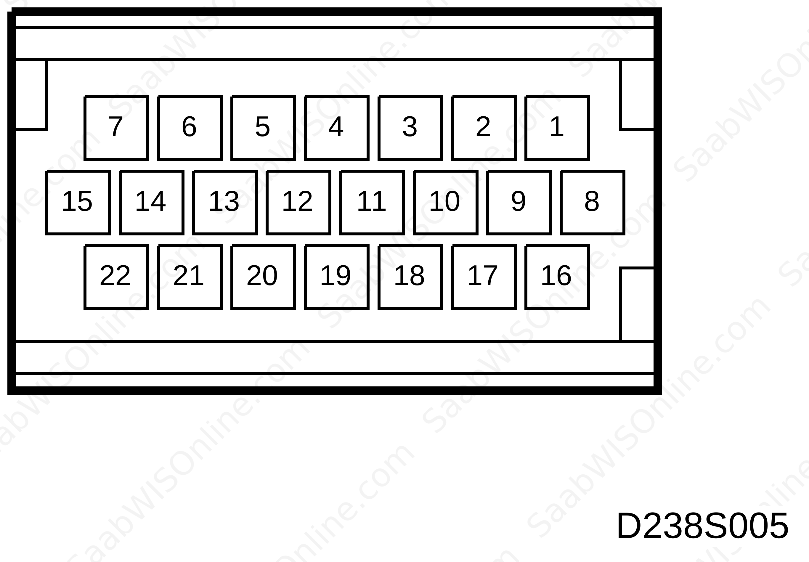
|
Pin No.
|
Lead colour
|
Component/function
|
In/Out
|
Test conditions
|
Across
|
Test reading
|
See
|
|
1
|
BK
|
Ground
|
Out
|
Ignition ON
|
1-B-
|
<0.5 V
|

|
|
2
|
|
No connection
|
|
|
|
|
|
|
3
|
YE/WH
|
Steering wheel controls,
ground |
-
|
Ignition ON
|
3-B-
|
<0.1 V
|
|
|
4
|
BK/WH
|
Rheostat,
ground |
-
|
Ignition ON
|
4-B-
|
<0.1 V
|
|
|
5
|
BU/GN
|
Outdoor temperature sensor
ground |
-
|
Ignition ON
|
5-B-
|
<0.1 V
|
|
|
6
|
|
No connection
|
|
Temperature sensor, outdoor
|
|
|
|
|
7
|
|
No connection
|
|
|
|
|
|
|
8
|
YE/GY
|
Battery Voltage
+15 |
In
|
Ignition ON
|
8-B+
|
<0.5 V
|
|
|
9
|
WH
|
Bus (-)
|
In/Out
|
Ignition ON
|
9-1
|
2.5 V
|
|
|
10
|
BN
|
Filament monitor,
front lights |
In
|
Ignition ON
|
10-1 |
B+ |
|
|
11
|
YE/RD
|
Rheostat +
|
In
|
Ignition ON
“Max.” rheostat position. |
11-1 |
0 V |
|
|
|
|
|
|
“Min.” rheostat position
|
11-1
|
3.5 V
|
|
|
12
|
|
No connection
|
|
|
|
|
|
|
13
|
|
No connection
|
|
|
|
|
|
|
14
|
|
No connection
|
|
|
|
|
|
|
15
|
RE/WH
|
Battery Voltage +30
|
In
|
Ignition ON
|
5-B+
|
<0.5 V
|
|
|
16
|
GN
|
Bus +
|
In/Out
|
Ignition ON
|
16-1
|
2.5 V
|
|
|
17
|
YE/WH
|
Horn,
relay |
Out
|
Ignition ON
Horn NOT activated. |
17-1
|
B+
|
|
|
18
|
YE/BK
|
Steering wheel controls + (switches)
|
In
|
Ignition ON
Press the following buttons: |
|
-
|
|
|
|
|
|
|
Horn
|
18-1
|
0 V
|
|
|
|
|
|
|
VOL -
|
18-1
|
0.7 V
|
|
|
|
|
|
|
VOL +
|
18-1
|
1.2 V
|
|
|
|
|
|
|
SRC
|
18-1
|
1.8 V
|
|
|
|
|
|
|
SEEK >>
|
18-1
|
2.4 V
|
|
|
|
|
|
|
<< SEEK
|
18-1
|
3.0 V
|
|
|
|
|
|
|
NXT
|
18-1
|
3.6 V
|
|
|
|
|
|
|
Normal position
|
18-1
|
4.2 V
|
|
|
|
|
|
|
ON
|
18-1
|
0 V
|
|
|
19
|
YE/GN
|
Temperature sensor, outdoor
|
In
|
Ignition ON
Temperature readings: |
|
|
|
|
|
|
|
|
10°C/50°F
|
19-1
|
2.49 V
|
|
|
|
|
|
|
20°C/68°F
|
19-1
|
1.72 V
|
|
|
|
|
|
|
30°C/86°F
|
19-1
|
1.43 V
|
|
|
20
|
BU/RD
|
Parking heater / auxiliary heater
|
Out
|
Activated
|
20-1
|
0 V
|
|
|
|
|
|
|
Not activated
|
20-1
|
B+
|
|
|
21
|
GY/WH
|
Washer fluid,
level sensor |
In
|
Washer fluid present (closed contact).
|
21-1
|
0 V
|
|
|
|
|
|
|
No washer fluid present (open contact).
|
21-1
|
B+
|
|
|
22
|
BK/GN
|
Coolant,
level sensor |
In
|
Coolant present (closed contact).
|
22-1
|
0 V
|
|
|
|
|
|
|
No coolant present (open contact).
|
22-1
|
B+
|
|
> = greater than; < = less than; ~ = alternating current (LP: LOGIC PROBE P = select pulse; p = visible pulse)
This project is supported by memberships and donations. If you use this site, please consider Joining SCNA and/or making a donation.
Our Friends