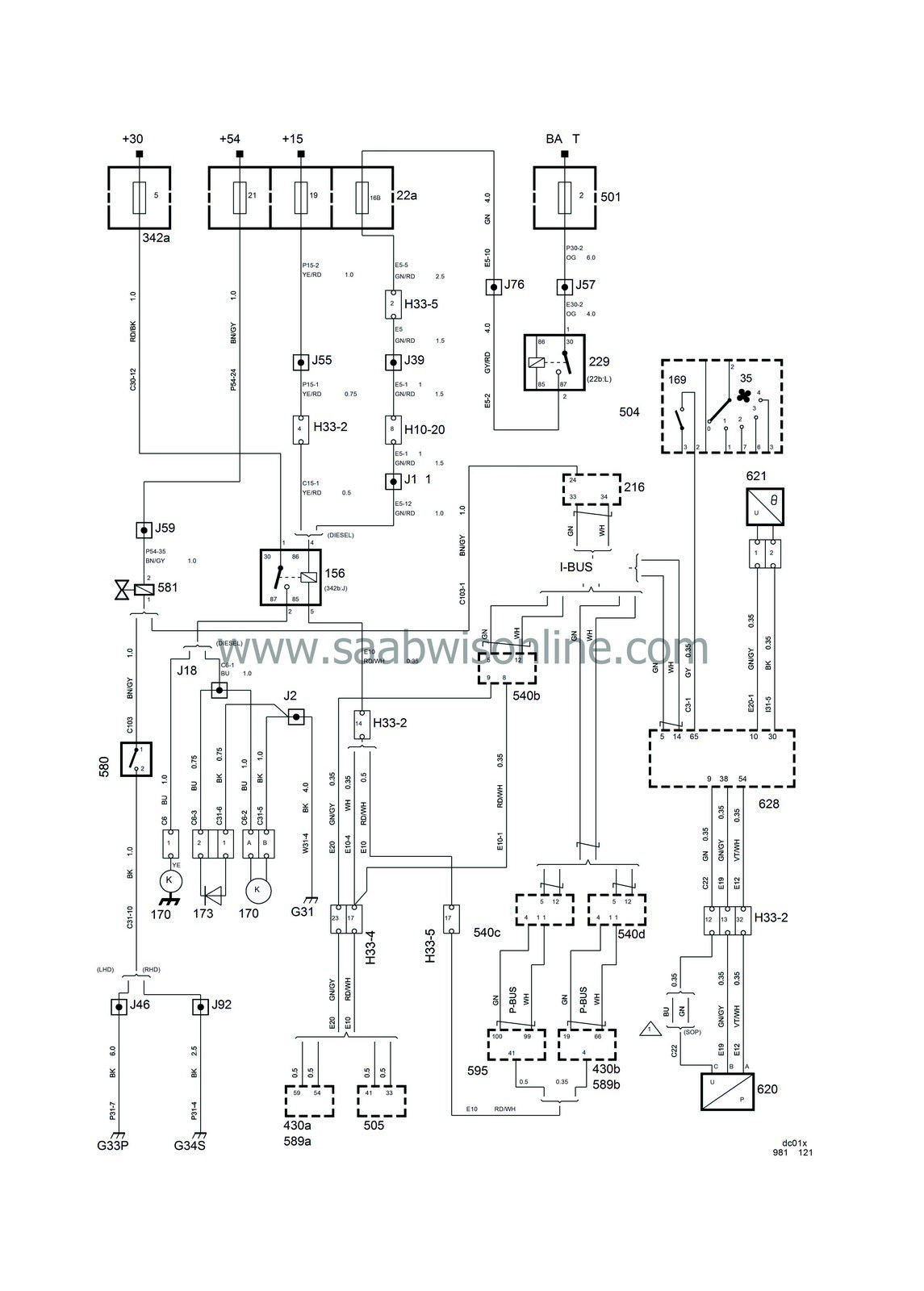
Air conditioning A/C
| Air conditioning A/C |
| List of components |
| No. | Name Location | Illustration |
|
Components |
||
|
22a
|
Main fuse box, dashboard
on end of dashboard by driver's door |

|
|
35
|
Switch, ventilation fan
in heating and ventilation control panel |

|
|
156
|
Relay, A/C compressor
in engine bay relay box |

|
|
169
|
A/C switch
in heating and ventilation control panel |

|
|
170
|
A/C compressor
on right-hand side of engine |

|
|
173
|
Diode, A/C compressor
on right-hand side of radiator member |

|
|
216
|
ACC control module
under radio |

|
|
229
|
Main relay, engine management system
in dashboard relay box |

|
|
342a
|
Main fuse box, engine bay
on left-hand side of engine bay below windscreen |

|
|
430a
|
Control module, Trionic T5
on right-hand side of cabin below A-pillar |

|
|
430b
|
Control module, Trionic T7
on right-hand side of cabin below A-pillar |

|
|
501
|
Main fuse box, maxi-fuses
next to the battery |

|
|
504
|
Control panel, heat and ventilation; under the radio
|
|
|
505
|
Control module, Motronic 2.10.3
on right-hand side of cabin below A-pillar |

|
|
540
|
Main instrument unit
in dashboard in front of driver |
b
c d |
|
580
|
Microswitch, air-mixing damper
on end of heater housing at air-mixing damper shaft |

|
|
581
|
Solenoid valve, heat exchanger
on front edge of heater housing |

|
|
589a
|
Control module, Trionic T5 OBDII
on right-hand side of cabin inside side trim under A-pillar |

|
|
589b
|
Control module, Trionic T7 OBDII
on right-hand side of cabin inside side trim under A-pillar |

|
|
595A
|
Control module, diesel, switch A
on right-hand side of cabin below A-pillar |

|
|
595B
|
Control module, diesel, switch B
on right-hand side of cabin below A-pillar |

|
|
620
|
A/C pressure sensor
below right-hand end of condenser |

|
|
621
|
Temperature sensor, A/C evaporator
on evaporator outlet pipe |

|
|
628
|
Control module, DICE
LHD: above dashboard relay box RHD: behind dashboard relay box |

|
|
10-pin connector |
||
|
H10-20
|
In engine bay by pedal position sensor
|

|
|
33-pin connector |
||
|
H33-2
|
Black connector on console below left A-pillar
|

|
|
H33-4
|
LHD:
Black connector on bulkhead behind glove box
RHD: Black connector under engine control module |

|
|
H33-5
|
LHD:
Grey connector on bulkhead behind glove box
RHD: Grey connector under engine control module |

|
|
Crimped connections |
||
|
J2
|
In branching point to front right wheel sensor
|

|
|
J11
|
Approx. 90 mm from branching point left wheel sensor towards ABS unit
|

|
|
J18
|
Approx. 200 mm from branching point grounding point G31 towards A/C compressor
|

|
|
J39
|
Approx. 80 mm from branching point connector H33-5 towards connector
|

|
|
J46
|
LHD:
Approx. 200 mm from branching grounding point G33 towards control module DICE
RHD: -- |

|
|
J55
|
LHD:
Approx. 240 mm from branching point DICE control module towards connector H33-2
RHD: Approx. 100 mm from rheostat branching point towards light switch |

|
|
J57
|
LHD:
Approx. 30 mm from branching grounding point G33 towards control module DICE
RHD: Approx. 90 mm from branching main fuse box towards main fuse box |

|
|
J59
|
LHD:
Approx. 40 mm from branching grounding point G33 towards main fuse box
RHD: Approx. 130 mm from branching main fuse box towards main fuse box |

|
|
J76
|
LHD:
Approx. 110 mm from branching grounding point G33 towards control module DICE
RHD: Approx. 70 mm from main relay board |

|
|
J92
|
LHD:
--
RHD: Approx. 140 mm from branching control module DICE towards main fuse box |

|
|
Grounding points |
||
|
G31
|
Grounding point, right-hand structural member
in engine bay on side panel in front of right-hand wheel housing |

|
|
G33P
|
Grounding point, connector bracket (power)
below left-hand A-pillar |

|
|
G34S
|
Grounding point, control module bracket (signal)
below right-hand A-pillar |

|


