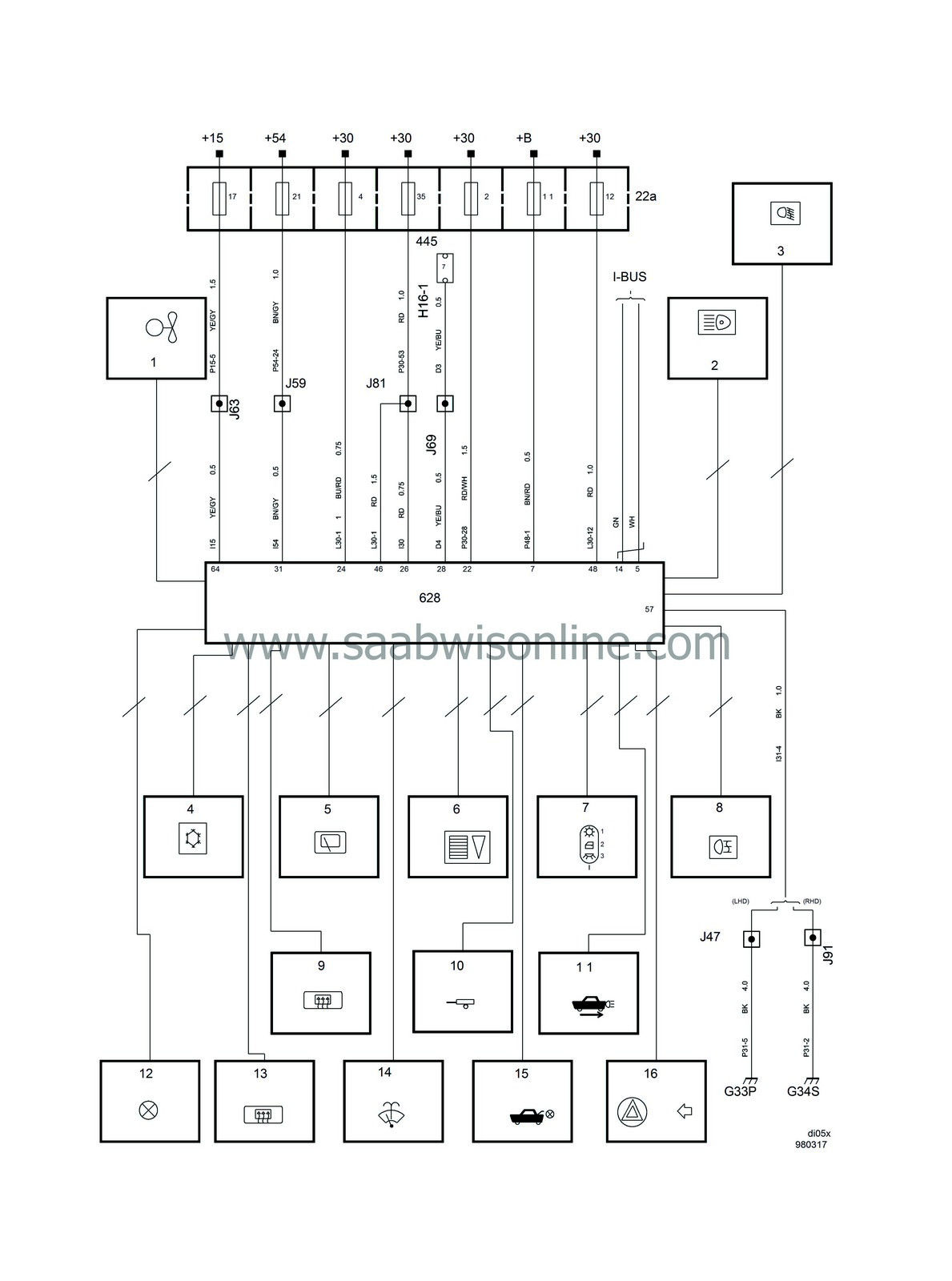
|
No.
|
Name
Location
|
Fig.
|
|
Components
|
|
22a
|
Main fuse board, dashboard,
on end of the dashboard by the driver's door
|

|
445
|
Data link connector, 16-pin, CARB,
under dashboard by steering column
|

|
628
|
Control module, DICE,
LHD:
above dashboard relay board
RHD:
behind dashboard relay board
|

|
|
16-pin connector
|
|
H16-1
|
under dashboard by steering column
|

|
|
Crimps
|
|
J47
|
LHD:
About 180 mm from branching point control module DICE towards brake light switch
RHD:
--
|

|
J59
|
LHD:
About 40 mm from branching point grounding point G33 towards fuse board
RHD:
About 130 mm from branching point fuse board towards fuse board
|

|
J63
|
LHD:
Approx. 200 mm from the MIU branching point, towards the SID
RHD:
About 50 mm from branching point rheostat towards light switch
|

|
J69
|
LHD:
Approx. 100 mm from branching of SID towards grounding point G34
RHD:
Approx. 250 mm from branching of SID towards radio
|

|
J81
|
LHD:
Approx. 430 mm from rear edge of connector for control module DICE
RHD:
About 30 mm from light switch branching point towards MIU
|

|
J91
|
LHD:
--
RHD:
Approx. 110 mm from DICE control module branching point towards engine bay
|

|
|
Grounding points
|
|
G33P
|
Grounding point connector bracket (Power),
in cabin below left A-pillar
|

|
G34S
|
Grounding point control module bracket (Signal),
in cabin below right A-pillar
|

|


