Fuel rail with injectors (B204i/E)
|
|
Fuel rail with injectors (B204i/E)
|
 Warning
|
|
Removal of the fuel rail involves partial dismantling of the car's fuel system. The following points must therefore be observed in connection with this work:
|
|
•
|
Work only in a well-ventilated area! If approved equipment for the extraction of fuel vapour is available, be sure to use it.
|
|
•
|
Wear suitable gloves! Prolonged contact with fuel can cause skin irritation or dermatitis.
|
|
•
|
Keep a class BE fire extinguisher close at hand! Beware of sparks caused by short circuits when connecting and disconnecting leads in electrical circuits for example.
|
|
•
|
No smoking anywhere in the vicinity.
|
|
|
|
|
|

|
Important
|
|
The utmost cleanliness must be observed when handling the fuel rails and injectors. Wash around the injectors, fuel rail and intake manifold and dry with compressed air.
|
|
|
|
Important
|
|
To minimize any residual fuel pressure, remove the fuel pump fuse no. 32 while the engine is idling. Turn off the ignition once the engine has stopped. Refit the fuse.
|
|
|
|
1.
|
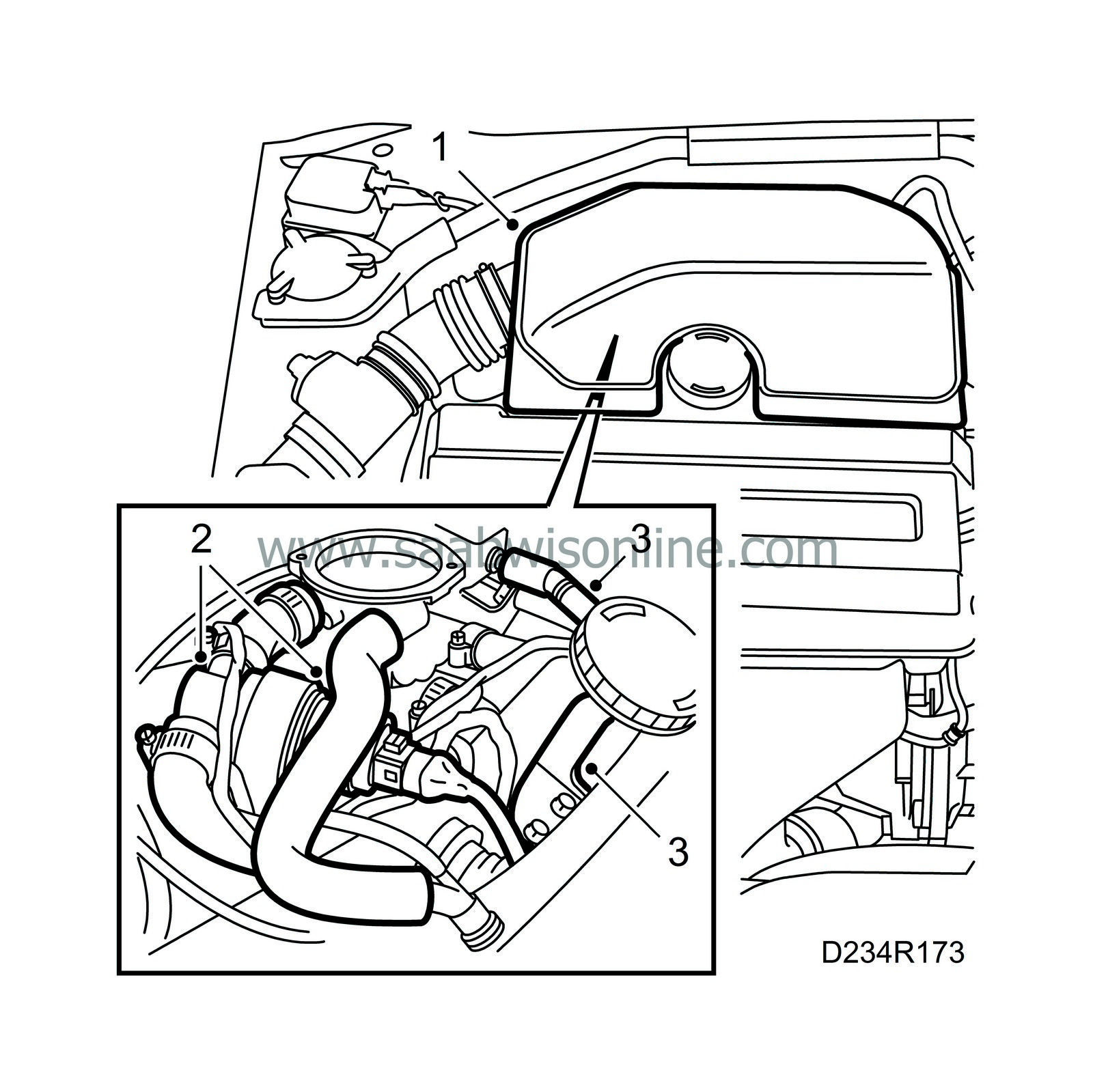
Remove the resonator (cover on turbo engines).
|
|
2.
|
Remove the crankcase ventilation hose and the idle speed control valve.
|
|
3.
|
Remove the bracket for the dipstick holder as well as the accelerator and cruise control cables.
|
|
4.
|
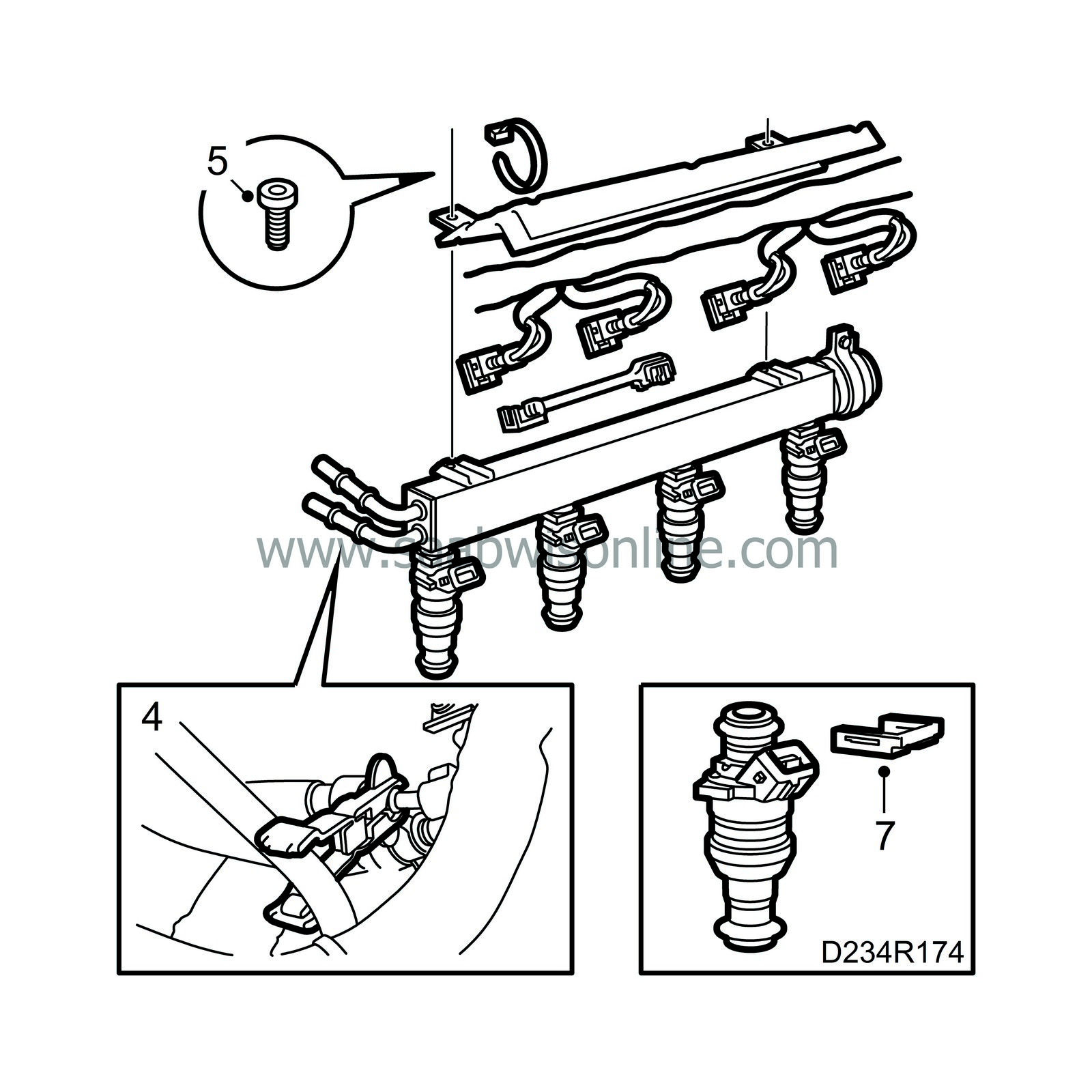
Use special tool no. 83 95 261 to detach the delivery and return fuel lines from the fuel rail.

|
|
5.
|
Remove the 4 retaining bolts, 2 at each end of the fuel rail. Remove the 2 protective rails and unplug the electric connections to the injectors.
|
|
6.
|
Carefully lift up the fuel rail.
|
|
7.
|
Remove the retaining clips securing the injectors to the fuel rail and pull out the injectors.
|

|
1.
|
Fit the injectors to the fuel rail and secure them with the retaining clips
|
|
2.
|
Fit the electric connections to the injectors and check that they are correct.
|
|
3.
|
Carefully press the fuel rail in place.
|
|
4.
|
Fit the protective rails and the 4 retaining bolts.
|
|
5.
|
Fit the delivery and return lines to the fuel rail.
|
|
6.
|
Fit the accelerator and cruise control cables as well as the bracket for the dipstick holder.
|
|
7.
|
Fit the idle speed control valve and the crankcase ventilation hose.
|
|
8.
|
Fit the resonator (the cover on turbo engines).
|
|
Important
|
|
The O-rings between the resonator and the throttle body can end up in the wrong position when being fitted, which will result in air entering the engine that has not passed through the mass air flow sensor. This can cause driveability problems and consequently fault diagnosis procedures.
|
|
When any work is done that involves removing the resonator from the throttle body, the following steps must always be taken:
|
|
•
|
Check the condition of the O-rings and that they are properly seated. Replace any that are deformed.
|
|
•
|
Grease the O-rings with acid-free petroleum jelly.
|
|
|


 Warning

