
Test readings, control module connections
| Test readings, control module connections |


The following chapter contains readings and directions for measuring signals/levels on the Motronic control module.
| Keep in mind: |
| • |
Note the measuring conditions, use common sense when considering the measurement results.
|
|
| • |
The specified values are with the ignition in the ON position unless otherwise stated.
|
|
| • |
First, check that the control module is supplied with power and that it is grounded.
|
|
| • |
Then check all the inputs and signals from other systems.
|
|
| • |
Finally, check the control module outputs. Remember that the test readings do not indicate whether the actuator is working.
|
|
| • |
If any measured value is incorrect, use the wiring diagram to diagnose which leads, connections or components that should be checked further.
|
|
| • |
The stated values refer to calibrated Fluke 88/97.
|
|
| • |
The test values % (+) and ms (+) indicate the pulse ratio and pulse length of the signal respectively. A test instrument with pulse ratio respective pulse width measuring capacity must be used. The sign indicates positive trigger pulse, TRIG+.
|
|
> = greater than; < = less than
» = similar to; ∼ = alternating current
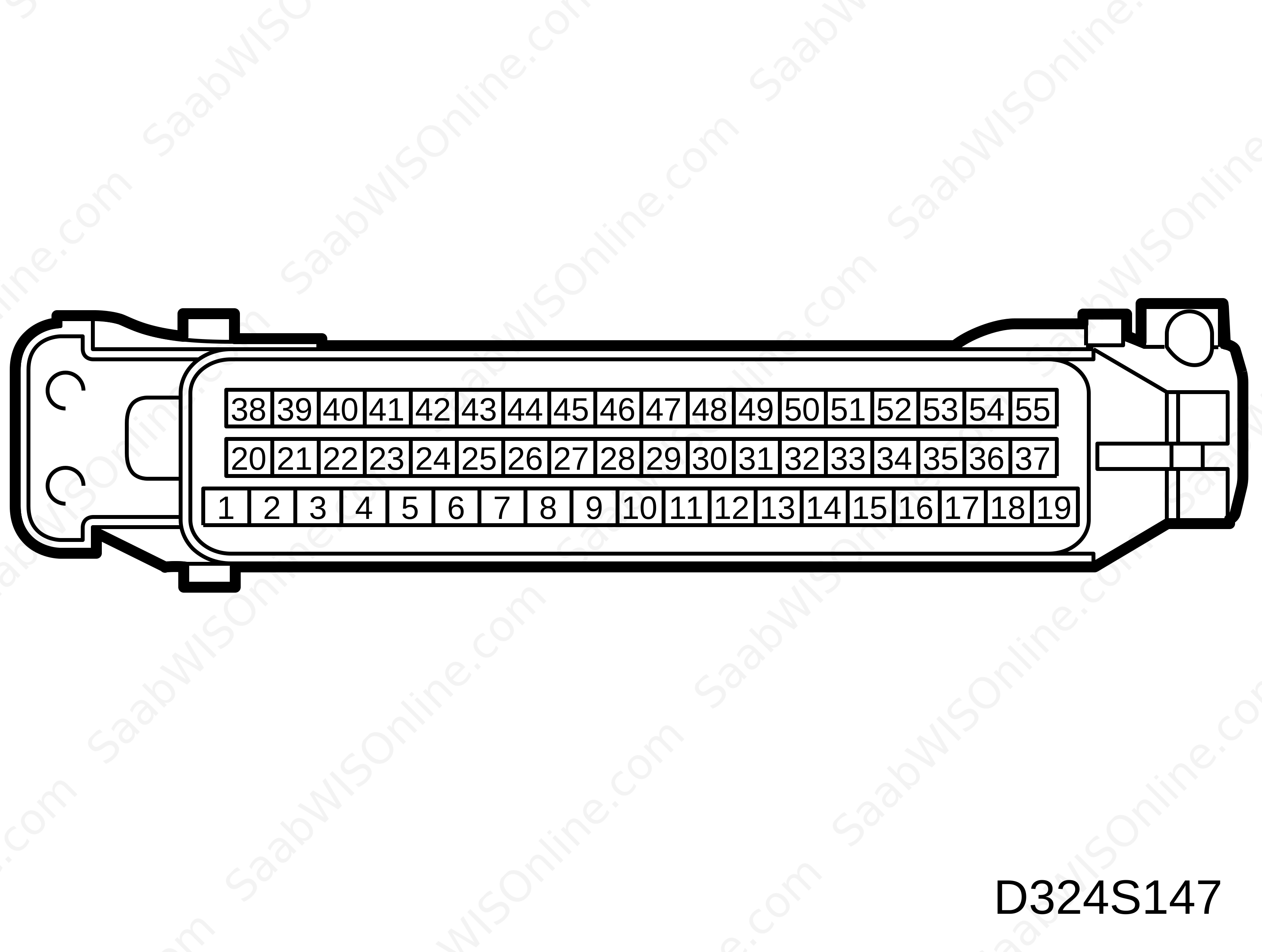
|
Pin
|
Colour
|
Component/Function
|
In/Out
|
Test conditions
|
Value
|
Between X-Y
|
|
1
|
GN
|
Ignition coil
|
Out
|
Ignition ON
|
Batt+
|
1 - 14
|
|
Idling speed
|
»
0.65 V
|
37 - 1
|
||||
|
2
|
BK
|
Power ground
|
In
|
Idling speed
|
< 0.1 V
|
2 - 14
|
|
3
|
WH
|
Fuel pump relay
|
Out
|
Ignition ON
|
Batt+
|
3 - 14
|
|
|
|
|
|
Starter motor cranking, idling speed
|
0 Volts
|
|
|
4
|
VT
|
Idle air control valve (OPEN)
|
Out
|
Idling speed, warm engine
|
»
2-5 V
» 2-5 ms 100 Hz |
37 - 4
|
|
5
|
BN
|
EVAP canister purge valve, fuel tank
|
Out
|
Ignition ON
|
Batt+
|
5 - 14
|
|
Idling speed, warm engine
|
0.3-0.5 V
15 Hz |
37 - 5
|
||||
|
6
|
GN/RD
|
Engine speed
|
In
|
Idling speed
|
»
3 V
» 30 Hz |
37 - 6
|
|
2500 rpm
|
»
85 Hz
|
6 - 14
|
||||
|
7
|
GY/WH
|
Mass air flow sensor
|
In
|
Idling speed
|
»
1 V
|
7 - 26
|
|
2500 rpm
|
»
1.5 V
|
|||||
|
Wide open throttle
|
»
3.2 V
|
|||||
|
8
|
YE
|
Position sensor,
camshaft |
In
|
Ignition ON
rotate engine |
0/5 Volts
|
8 - 14
|
|
Idling speed
|
»
4.3 V
» 7.5 Hz |
|||||
|
9
|
PK/BK
|
Vehicle Speed (wheel speed FR)
|
In
|
Ignition ON, rotate FR
|
0/10 V
|
9 - 14
|
|
10
|
BK
|
Reference ground, oxygen sensor
|
In
|
Idling speed
|
<0.1 V
|
10 - 14
|
|
11
|
BK
|
Knock Sensor
|
In
|
3000 rpm
|
>20 mV∼
|
11 - 14
|
|
12
|
BK
|
Throttle position sensor + Camshaft
|
Out
|
Ignition ON
|
5 Volts
|
12 - 14
|
|
13
|
GY/WH
|
Diagnosis L-wire
|
In
|
Ignition ON
|
»
10 Volts
|
13 - 14
|
|
14
|
BK
|
Power ground
|
In
|
Idling speed
|
<0.1 V
|
14 - Batt-
|
|
15
|
No connection
|
|||||
|
16
|
GN
|
Injector CYL3
|
Out
|
Idling speed, warm engine
|
»
0.3 V
» 3 ms » 8 Hz |
37 - 16
|
|
17
|
GY
|
Injector CYL1
|
Out
|
Idling speed, warm engine
|
»
0.3 V
» 3 ms » 8 Hz |
37 - 17
|
|
18
|
PK/WH
|
Battery voltage + 30 (memory)
|
In
|
Battery = OK
|
Batt+
|
18 - 14
|
|
19
|
BK
|
Signal ground
|
In
|
Idling speed
|
<0.1 V
|
19 - 14
|
|
20
|
No connection
|
|||||
|
21
|
YE/GN
|
CHECK ENGINE (MIL)
|
Out
|
Ignition ON
MIL on |
Batt+
|
37 - 21
|
|
Ignition ON
MIL off |
0 Volts
|
|||||
|
22
|
WH
|
IAC-valve, (CLOSE)
|
Out
|
Idling speed, warm engine
|
7-10 V
6-8 ms 100 Hz |
37 - 22
|
|
23
|
No connection
|
|||||
|
24
|
BK
|
Power ground
|
In
|
Idling speed
|
<0.1 V
|
24 - 14
|
|
25
|
No connection
|
|||||
|
26
|
BU/YE
|
Ground, Mass air flow sensor
|
Out
|
Idling speed
|
<0.1 V
|
26 - 14
|
|
27
|
YE/GY
|
Battery voltage +15
|
In
|
Idling speed
|
Batt+
|
27 - 14
|
|
28
|
GN
|
Signal, oxygen sensor
|
In
|
Idling speed, warm engine
|
0-1 V
|
28 - 10
|
|
29
|
|
No connection
|
||||
|
30
|
BN/WH
|
Sensor ground
|
Out
|
Idling speed
|
<0.1 V
|
30 - 14
|
|
31
|
No connection
|
|||||
|
32
|
No connection
|
|||||
|
33
|
RD/WH
|
Relay, air-conditioning
|
Out
|
Idling, A/C ON
|
Batt+
|
37 - 33
|
|
34
|
BN
|
Injector CYL2
|
Out
|
Idling speed, warm engine
|
»
0.3 V
» 3 ms » 8 Hz |
37 - 34
|
|
35
|
BU/BK
|
Injector CYL4
|
Out
|
Idling speed, warm engine
|
»
0.3 V
» 3 ms » 8 Hz |
37 - 35
|
|
36
|
BU/GY
|
Main relay
|
Out
|
Ignition OFF
|
Batt+
|
36 - 14
|
|
Ignition ON
|
0 Volts
|
|||||
|
37
|
GN/RD
|
Voltage supply
|
In
|
Ignition ON
|
Batt+
|
37 - 14
|
|
38
|
No connection
|
|||||
|
39
|
No connection
|
|||||
|
40
|
GN/RD
|
Coding for choice of gearbox
|
In
|
Ignition ON
|
B+ (aut)
|
40 - 14
|
|
Ignition ON
|
0 V (man)
|
|||||
|
41
|
GN/GY
|
Air-conditioning ON/OFF
|
In
|
Ignition ON
A/C ON |
Batt+
|
41 - 14
|
|
42
|
No connection
|
|||||
|
43
|
No connection
|
|||||
|
44
|
GN/BK
|
Electrical load
|
In
|
Radiator fan ON
|
Batt+
|
44 - 14
|
|
Radiator fan OFF
|
0
|
|||||
|
45
|
GN/WH
|
Coolant temperature sensor
|
In
|
Ignition ON
90°C |
»
0.9 V
|
45 - 30
|
|
46
|
No connection
|
|||||
|
47
|
BK/WH
|
DRIVsignal
|
In
|
Ignition ON
R-D-3-1 |
Batt+
|
47 - 14
|
|
48
|
YE
|
Crankshaft position sensor
|
In
|
Starter motor cranking
|
2-5 V∼
|
48 - 49
|
|
Idling speed
|
7-11 V∼
|
|||||
|
2500 rpm
|
»
20 V ∼
|
|||||
|
49
|
BK
|
Crankshaft position sensor
|
In
|
Starter motor cranking
|
2-5 V∼
|
49 - 48
|
|
Idling speed
|
7-11 V∼
|
|||||
|
2500 rpm
|
»
20 V ∼
|
|||||
|
50
|
No connection
|
|||||
|
51
|
OG/WH
|
Torque reduction
|
In
|
Ignition ON
|
Batt+
|
51 - 14
|
|
Gear
|
0 V
|
|||||
|
52
|
GN/OG
|
Throttle Position to TCM
|
Out
|
Idling speed
|
»
1.3 V
100 Hz |
52 - 14
|
|
2500 rpm
|
»
2.2 V
100 Hz |
|||||
|
Wide open throttle
|
»
12 V
100 Hz |
|||||
|
53
|
BU/WH
|
Throttle position sensor
|
In
|
Closed throttle position
|
»
0.6 V
|
53 - 30
|
|
Wide open throttle
|
»
4.5 V
|
|||||
|
54
|
BU/GN
|
Coding
|
||||
|
55
|
GY/BK
|
Data link
|
In/Out
|
Ignition ON
Diagnostic instrument connected |
»
11 V
|
55 - 14
|
This project is supported by memberships and donations. If you use this site, please consider Joining SCNA and/or making a donation.
Our Friends