Mass air flow sensor
| Mass air flow sensor |
| Mass air flow sensor |
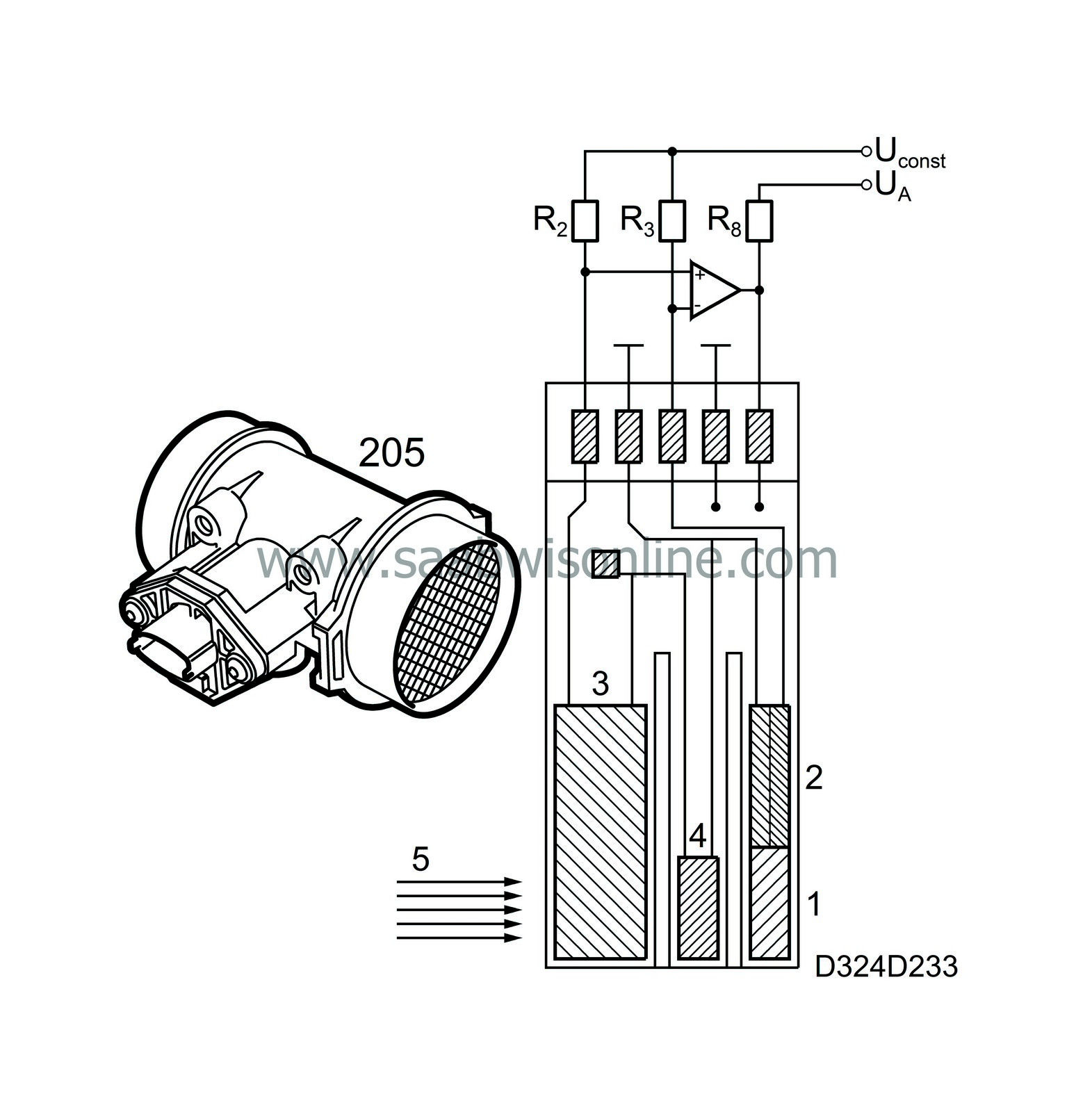
In the Motronic systems there is an electrically heated sensor element encapsulated in a film base that registers the air mass consumed by the engine.
The heated sensor element consists of a resistive sensor (1), a thermal resistor (2), a temperature sensor (3) and a calibrating resistor for the temperature sensor (4).
The resistive sensor is part of the so called compensating circuit, which leads current through the thermal resistor in such a way that its temperature remains constant.
Because the thermal resistor is connected to the resistive sensor, the resistive sensor will also maintain a constant temperature.
When the engine load and consequently the incoming air mass (5) increases, the cooling effect on the sensor increases. This forces the compensating circuit to increase the current (and temperature) through the thermal resistor.
We can therefore see that the current consumption through the thermal resistor is controlled by the engine load and that the voltage drop that arises across the resistor is directly proportional to the air mass intake.
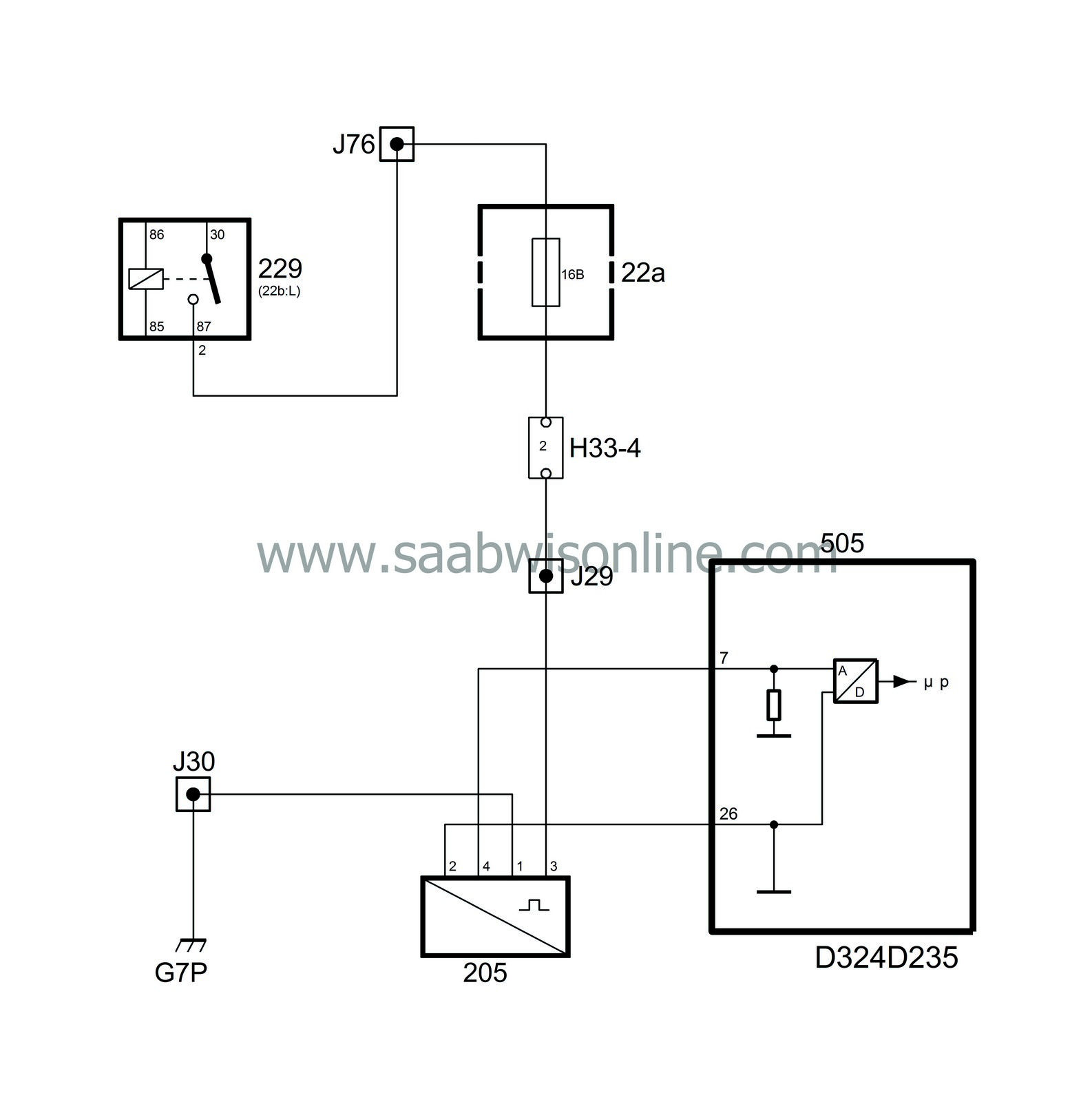
The voltage drop is taken out across pin 1 and 4 on the mass air flow sensor and the control module receives the information via pin 7.
The sensor does not require burning off as is the case on a mass air flow sensor with hot wire.
Should the mass air flow sensor function stop for some reason, the control is temporarily taken over by the throttle potentiometer, which gives the control module information about the throttle position and in this way provides a well functioning Limp-home function.
The mass air flow sensor can only be changed as a complete unit.


The control module receives immediate information about engine load (air mass intake), via voltage variations on the control module pin 7.
The mass air flow sensor receives its power supply from the main relay pin 87 and has its ground connection in the power ground G7P.
The mass air flow sensor pin 2 takes signal ground from the control module pin 26.
Through the compensation in temperature which is desired when the increased air flow is counteracted by an increased current through the thermal resistor, the voltage drop also increases across the resistor and the voltage on pin 4 (and the control module pin 7) decreases. In that way the voltage on the control module pin 7 varies from approx. 5 volts when fully loaded to approx. 1 volt when idling. (When measuring with BOB at full throttle and without load the voltage is approx. 3 volts).
On faulty or failing signal on the control module pin 7, the CHECK ENGINE lamp (MIL) comes on and the system goes over to the Limphome position. In this position the control module uses the information from the throttle position sensor to control the amount of petrol.


