Bus communication
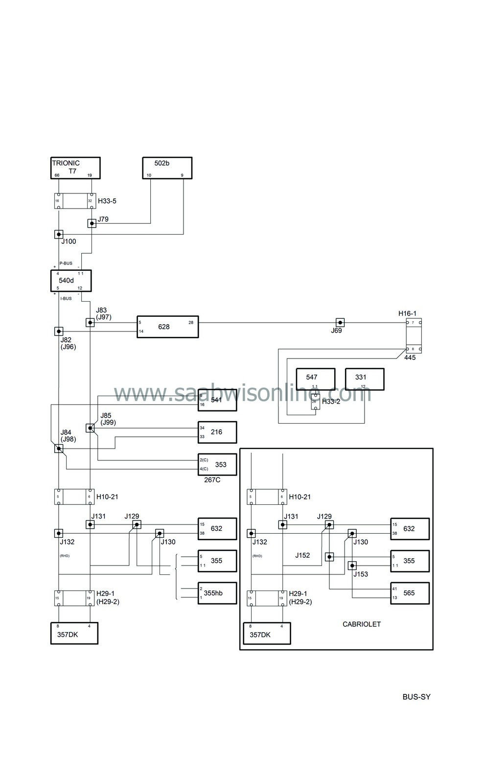
| Bus communication |
| • |
Control module ACC (216)
|
|
| • |
Radio connector C (267c)
|
|
| • |
Control module airbag/SRS (331)
|
|
| • |
Radio (353)
|
|
| • |
CD changer (355)
|
|
| • |
Control module PSM (357Dk)
|
|
| • |
Control module Trionic T7 (430b)
|
|
| • |
Transmission control module, TCM (502b)
|
|
| • |
MIU (540d)
|
|
| • |
SID (541)
|
|
| • |
Control module ABS (547)
|
|
| • |
Control module STC (565)
|
|
| • |
Control module Trionic T7 OBDII (589b)
|
|
| • |
Control module DICE (628)
|
|
| • |
Control module TWICE (632)
|
|
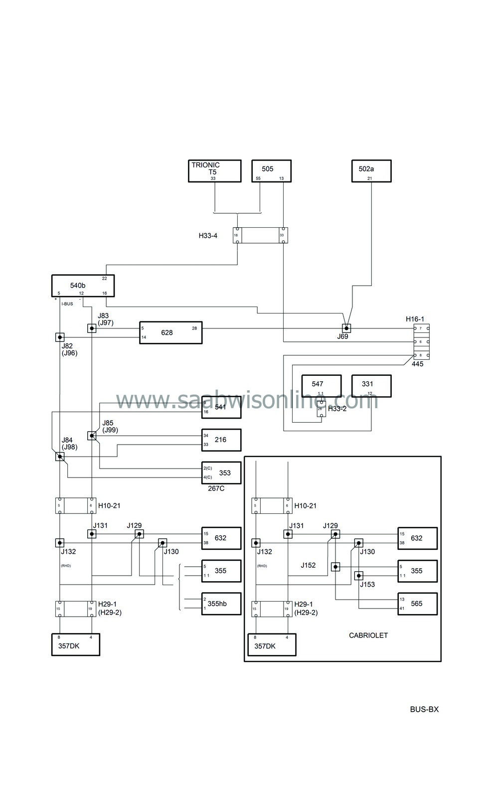
| Bus communication, other petrol engine variants |

| • |
Control module ACC (216)
|
|
| • |
Radio connector C (267c)
|
|
| • |
Control module airbag/SRS (331)
|
|
| • |
Radio (353)
|
|
| • |
CD changer (355)
|
|
| • |
Control module PSM (357Dk)
|
|
| • |
Control module Trionic T5 (430a)
|
|
| • |
Control module TCM (502)
|
|
| • |
Control module M2.10.3 (505)
|
|
| • |
MIU (540b)
|
|
| • |
SID (541)
|
|
| • |
Control module ABS (547)
|
|
| • |
Control module STC (565)
|
|
| • |
Control module Trionic T5 OBDII (589a)
|
|
| • |
Control module DICE (628)
|
|
| • |
Control module TWICE (632)
|
|
| Bus communication, diesel |

| • |
Control module ACC (216)
|
|
| • |
Radio connector C (267c)
|
|
| • |
Control module airbag/SRS (331)
|
|
| • |
Radio (353)
|
|
| • |
CD changer (355)
|
|
| • |
Control module PSM (357Dk)
|
|
| • |
MIU (540c)
|
|
| • |
SID (541)
|
|
| • |
Control module ABS (547)
|
|
| • |
Control module STC (565)
|
|
| • |
Control module EDC 15 (595)
|
|
| • |
Control module auxiliary heater (597)
|
|
| • |
Diesel pump (598)
|
|
| • |
Control module DICE (628)
|
|
| • |
Control module TWICE (632)
|
|
| P-bus and I-bus |

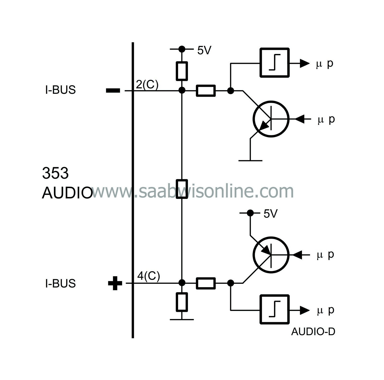
A bus is a number of wires on which information is sent digitally and serially. Digital means that the voltage difference between two wires has only two values, about 0V or 5V. The information is coded so that different combinations of pulses with values 0V and 5V have different meanings.
Serial means that the information is sent in ”packets” one after the other in rapid succession.
The bus is divided into the P-bus (Powertrain Bus) and the I-bus (Instrument Bus). Both buses are connected to the main instrument unit (MIU). The buses are electrically isolated from each other.
Only diesel-engined cars and cars with Trionic T7 have a P-bus. Other petrol-engined variants have the same engine management system and automatic transmission as the earlier 900 model (T5, M2.10.3 and TCM) and these have no bus connections.
As in the 9-5, the Airbag and ABS control modules are not bus-connected.
The diagnostics instrument is not directly connected to the bus but communicates via DICE, which is connected to the I-bus, and therefore has access to all the control modules connected to the bus.
The P-bus has a data transfer rate ten times higher than that of the I-bus. This is because the P-bus requires information with the least possible delay.
All information sent out by a control module is available to all other control modules connected to the bus. The MIU ensures that the information that is available on one bus is also available on the other.
The control modules send out information on the bus at regular intervals. The time between two transmissions depends on the information being transmitted and varies between 10 milliseconds (0.010 seconds) and one second. Information is also transmitted by the control module whenever the information changes.
The transmission of information between the control modules is achieved on two leads, bus+ (green lead) and bus- (white lead). The leads are twisted to increase tolerance to electrical interference.
| The main unit uses the following information |
| The main unit transmits the following information |


