Diagnostics communication
| Diagnostics communication |
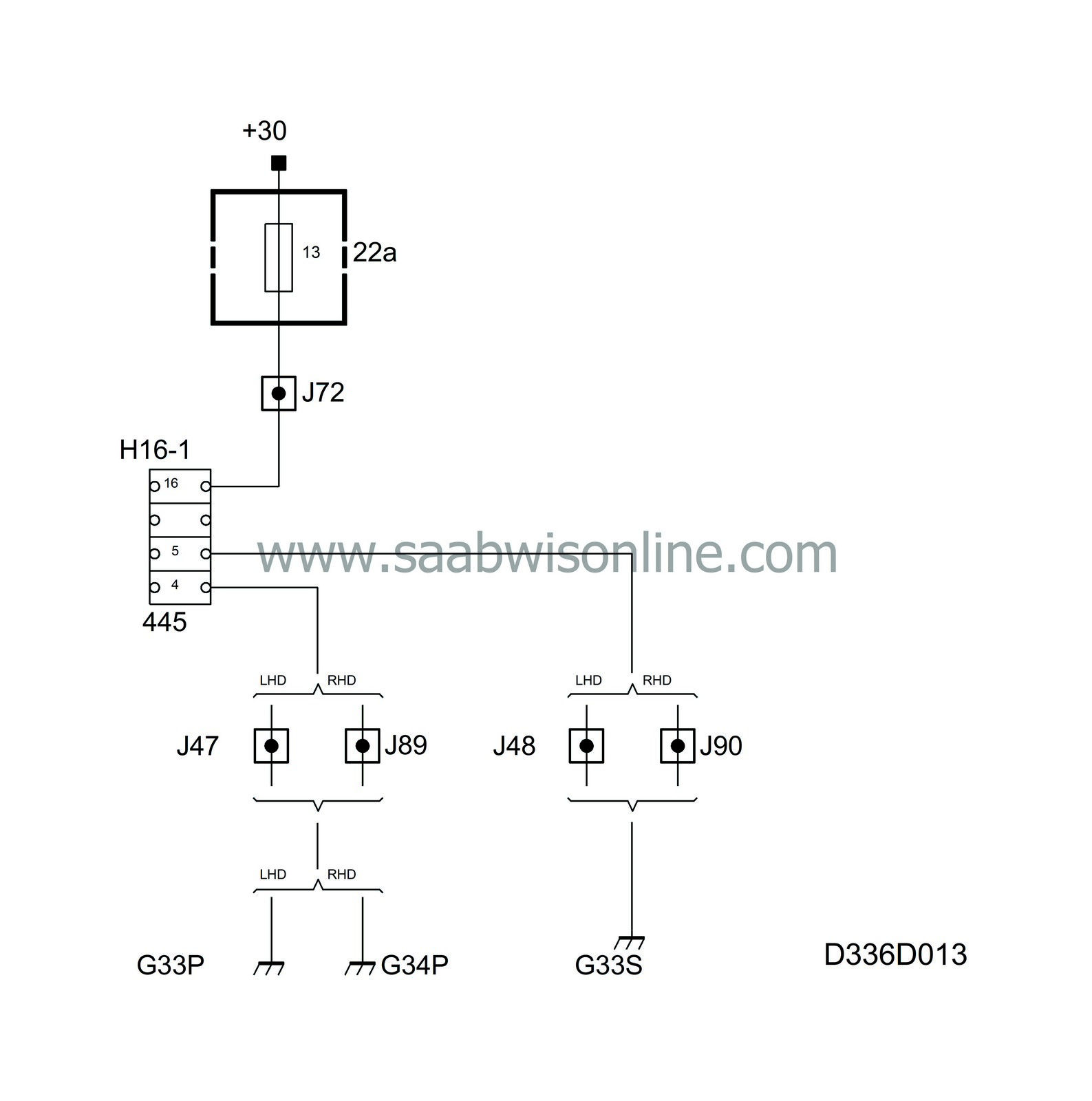
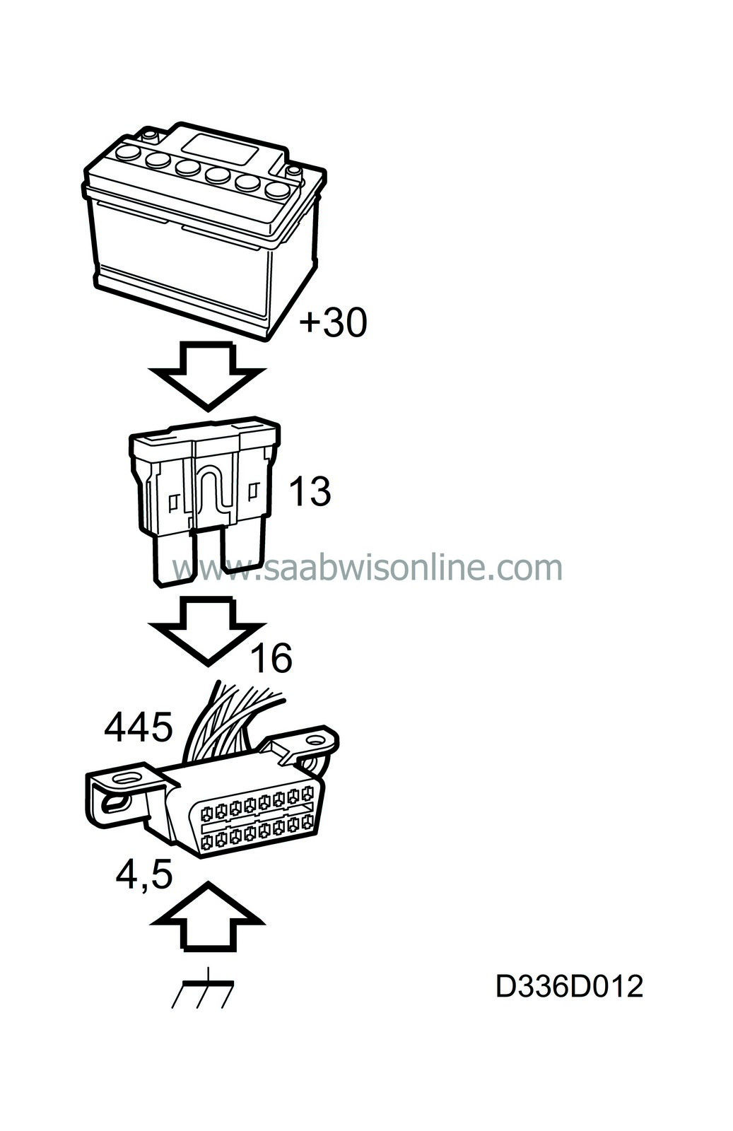
The data link connector is powered with +30 on pin 16 via fuse 13.
The data link connector pin 4 is grounded from grounding point G33P/G34P.
The data link connector pin 5 is grounded from grounding point G33S.
| TCM (cars with the Trionic T7 engine management system) |
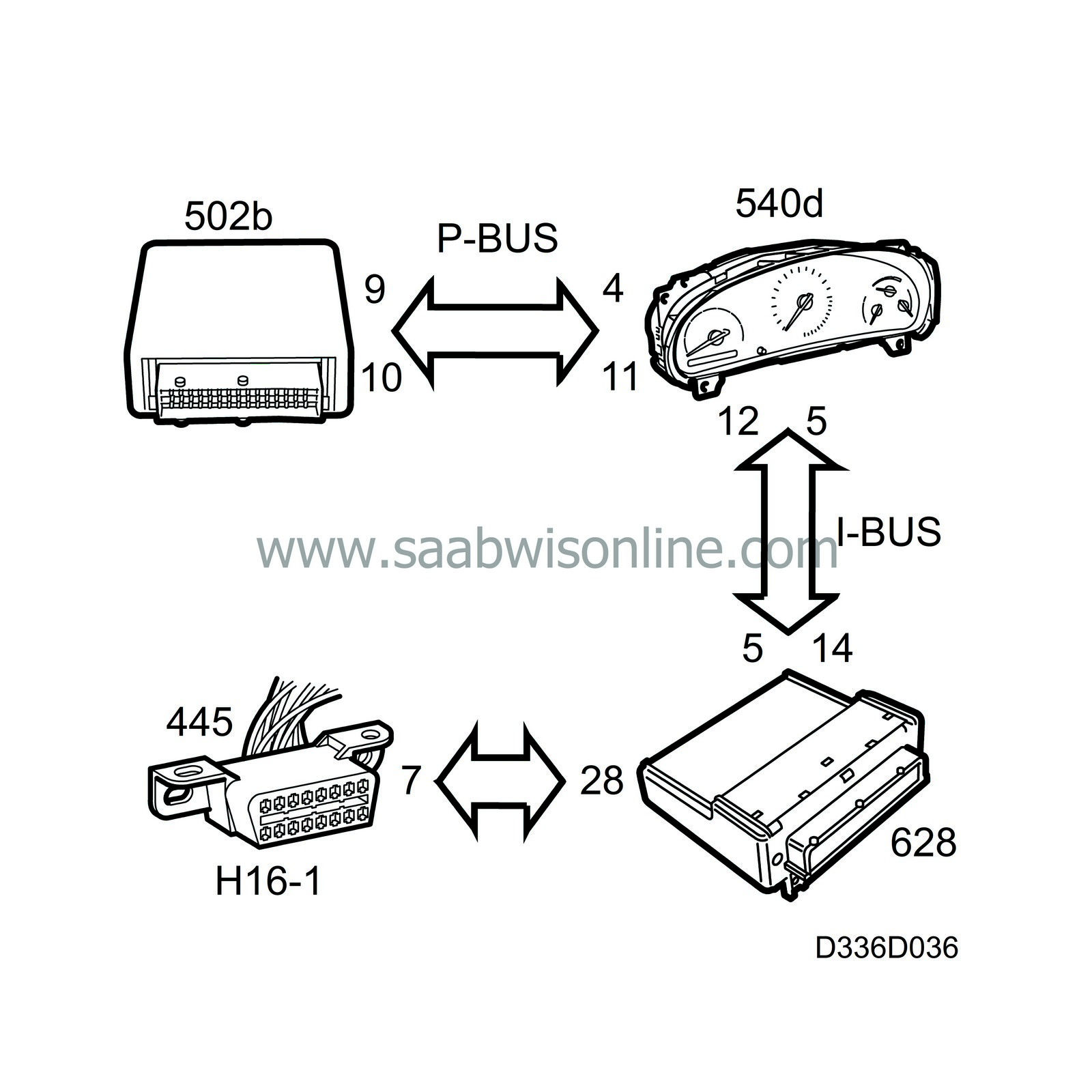
If the TCM is contacted, the diagnostic instrument will first call DICE and request diagnostics communication with the TCM. DICE sends the diagnostic instrument's request to the I-bus and the MIU then sends the diagnostics request to the P-bus and TCM,
This means that the DICE and MIU must both be supplied with current (awake) to enable contact with the TCM to be made.
Diagnostics
If none of the bus systems can be contacted then the fault must be either in the car or in the diagnostic tool.If the diagnostic tool can make contact with any of the systems concerned in another car, the fault will be in the car.
For further information about fault diagnosis of diagnostics communication with DICE or other system connected to a bus
see Bus diagnosis
| DICE and all bus systems except EDC 15 |
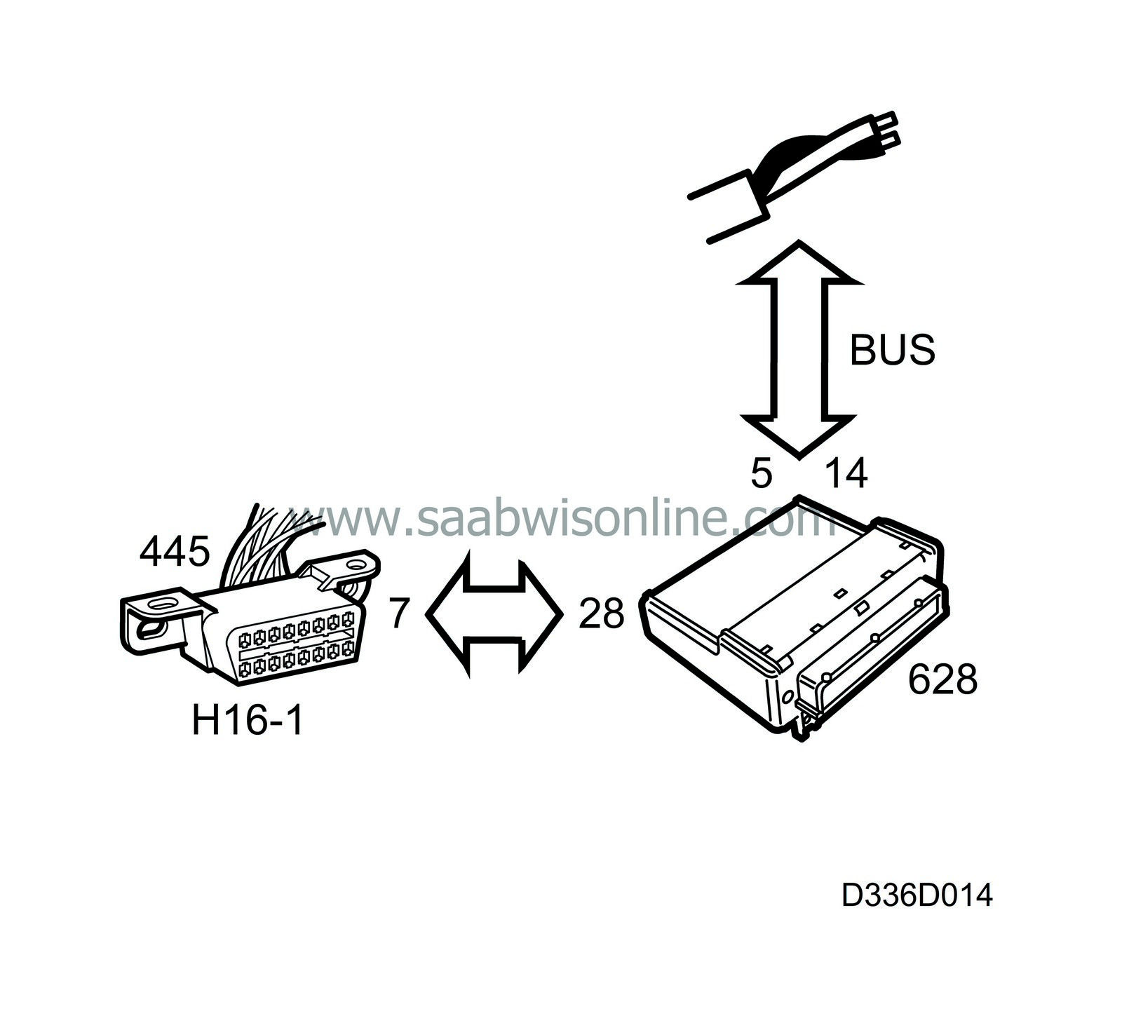
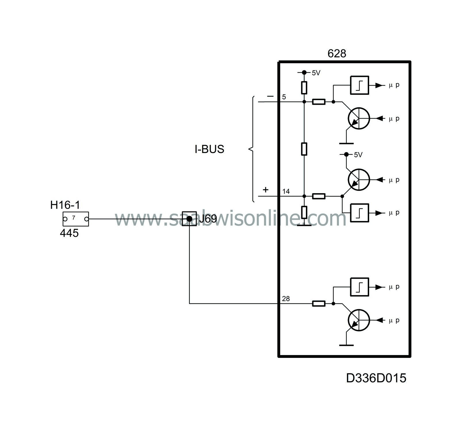
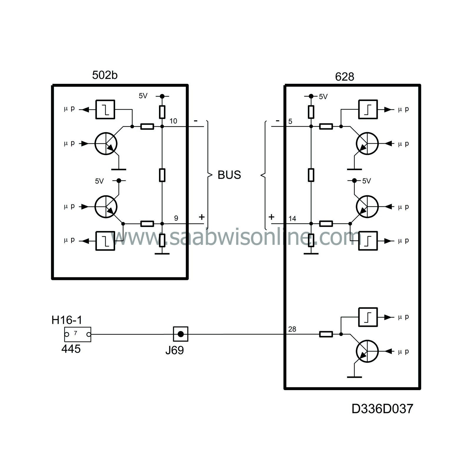
DICE is connected with a communication lead to the data link connector pin 7.
The diagnostic tool communicates digitally and serially with the DICE. Digitally means that the voltage difference between the lead and ground has only two values, in this case about 0 V and B+.
Serial means that the information is sent in ”packets” which are transmitted one after the other in rapid succession.
As the diagnostic tool has contact with DICE, it also has access to all the bus systems except EDC 15 which has a separate K lead.
If, for example, MIU is to be contacted, the diagnostic tool first calls DICE.
This means that DICE must be powered (awake) so that MIU can make contact.
Diagnostics
If none of the bus systems can be contacted then the fault must be either in the car or in the diagnostic tool.If the diagnostic tool can make contact with any of the systems concerned in another car, the fault will be in the car.
For further information about fault diagnosis of diagnostics communication with DICE or other system connected to a bus
see Bus diagnosis .
| Trionic T5 and Motronic |
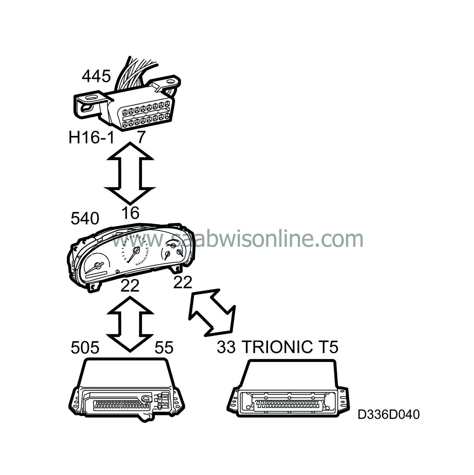
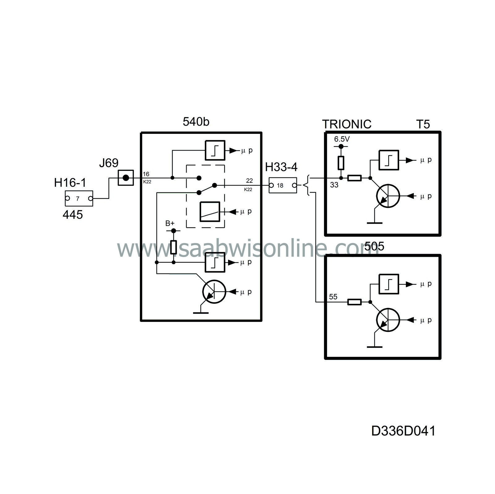
The K lead for the Trionic T5 and Motronic is connected via the MIU to pin 7 of the data link connector so that it can be used for the immobilization function.
Data link connector pin 6 is used by the diagnostic tool to activate the actuator in Motronic.
The diagnostic tool communicates digitally and serially with the selected system. Digitally means that the voltage difference between the lead and ground has only two values, in this case about 0 V and B+. The information is coded so that different combinations of 0 V and B+ pulses have different meanings, like which system is to be called.
Serial means that the information is sent in “packets” which are transmitted one after the other in rapid succession.
Diagnostics
If none of the systems can be contacted, the fault may be either in the car or the diagnostic tool. If the diagnostic tool can contact one of the systems concerned in another car, then the fault is in the car.In this case, first make sure that the control module is awake (as described in the technical data). If it is awake then the fault is probably in the lead between the data link connector and the control module.
| EDC 15 and DAH |
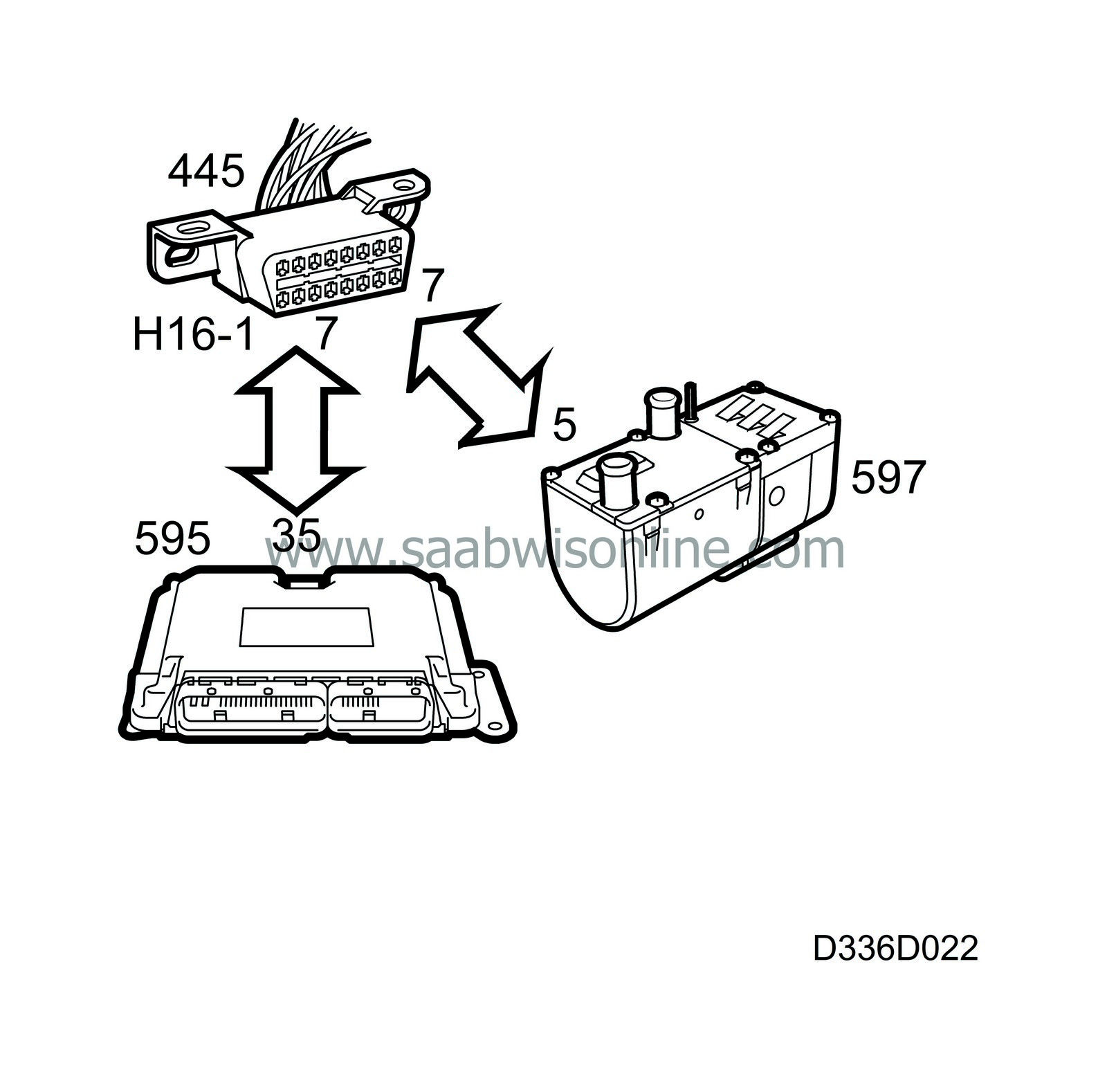
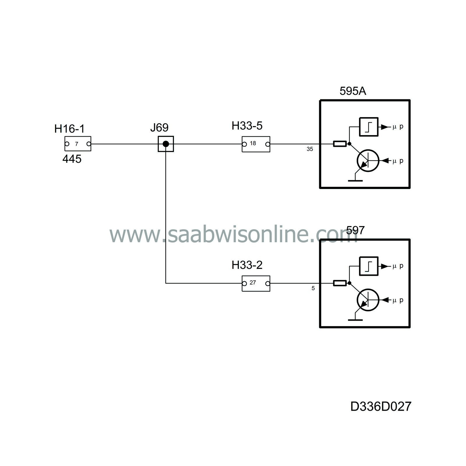
EDC 15 and DAH are each connected to the data link connector pin 7 through a communications lead.
The diagnostic tool communicates digitally and serially with the selected system. Digitally means that the voltage difference between the lead and ground has only two values, in this case about 0 V and B+. The information is coded so that different combinations of 0 V and B+ pulses have different meanings, like which system is to be called.
Serial means that the information is sent in “packets” which are transmitted one after the other in rapid succession.
Diagnostics
If none of the systems can be contacted, the fault may be either in the car or the diagnostic tool. If the diagnostic tool can contact one of the systems concerned in another car, then the fault is in the car.In this case, first make sure that the control module is awake (as described in the technical data). If it is awake then the fault is probably in the lead between the data link connector and the control module.
| ABS and SRS |
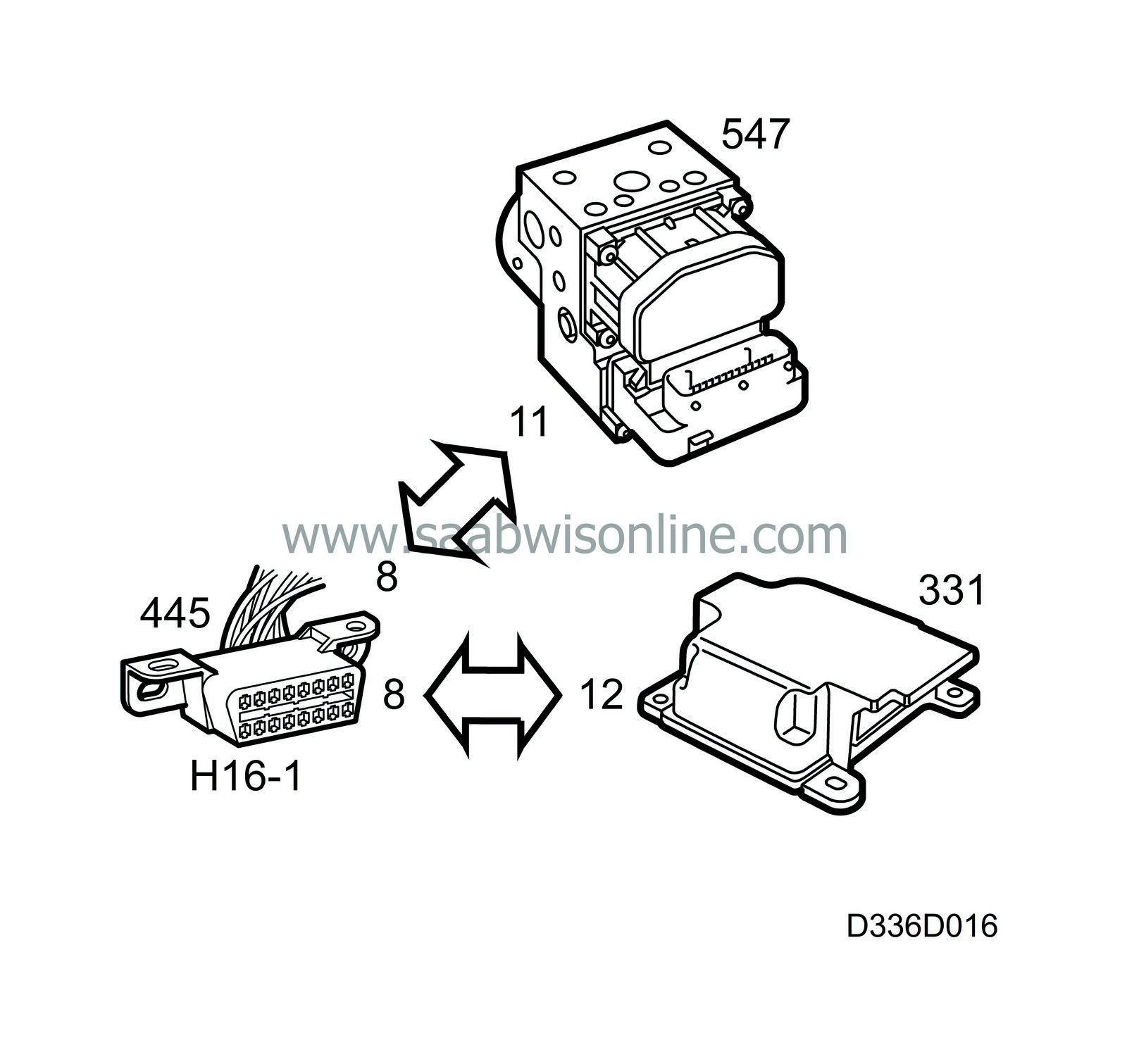
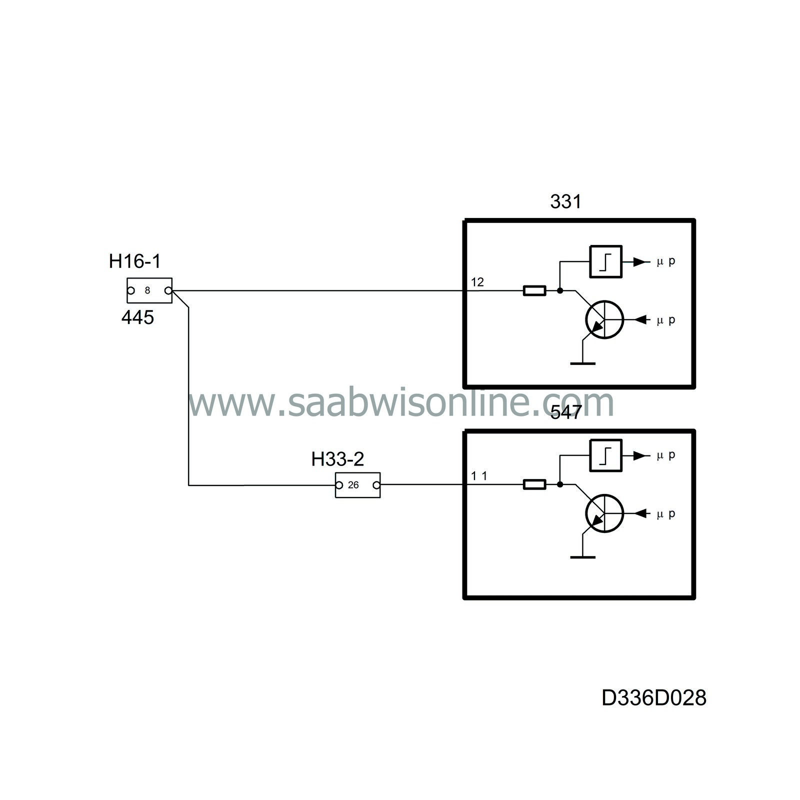
ABS and SRS are each connected to the data link connector pin 8 through a communications lead.
The diagnostics instrument communicates digitally and serially with the selected system. With digital communication the difference in voltage between the lead and ground has only two values, in this case about 0 V and B+. The information is coded so that different combinations of 0 V and B+ pulses have different meanings, such as whether the SRS or ABS is to be called.
Serial means that the information is sent in “packets” which are transmitted one after the other in rapid succession.
Diagnostics
If none of the systems can be contacted, the fault may be either in the car or the diagnostic tool. If the diagnostic tool can contact one of the systems concerned in another car, then the fault is in the car.In that case, first check that the control module is awake. The ABS and SRS warning lamps are tested by the control module as soon as the ignition is switched on. If the control module is awake, then the fault is probably in the lead between the data link connector and the control module.

