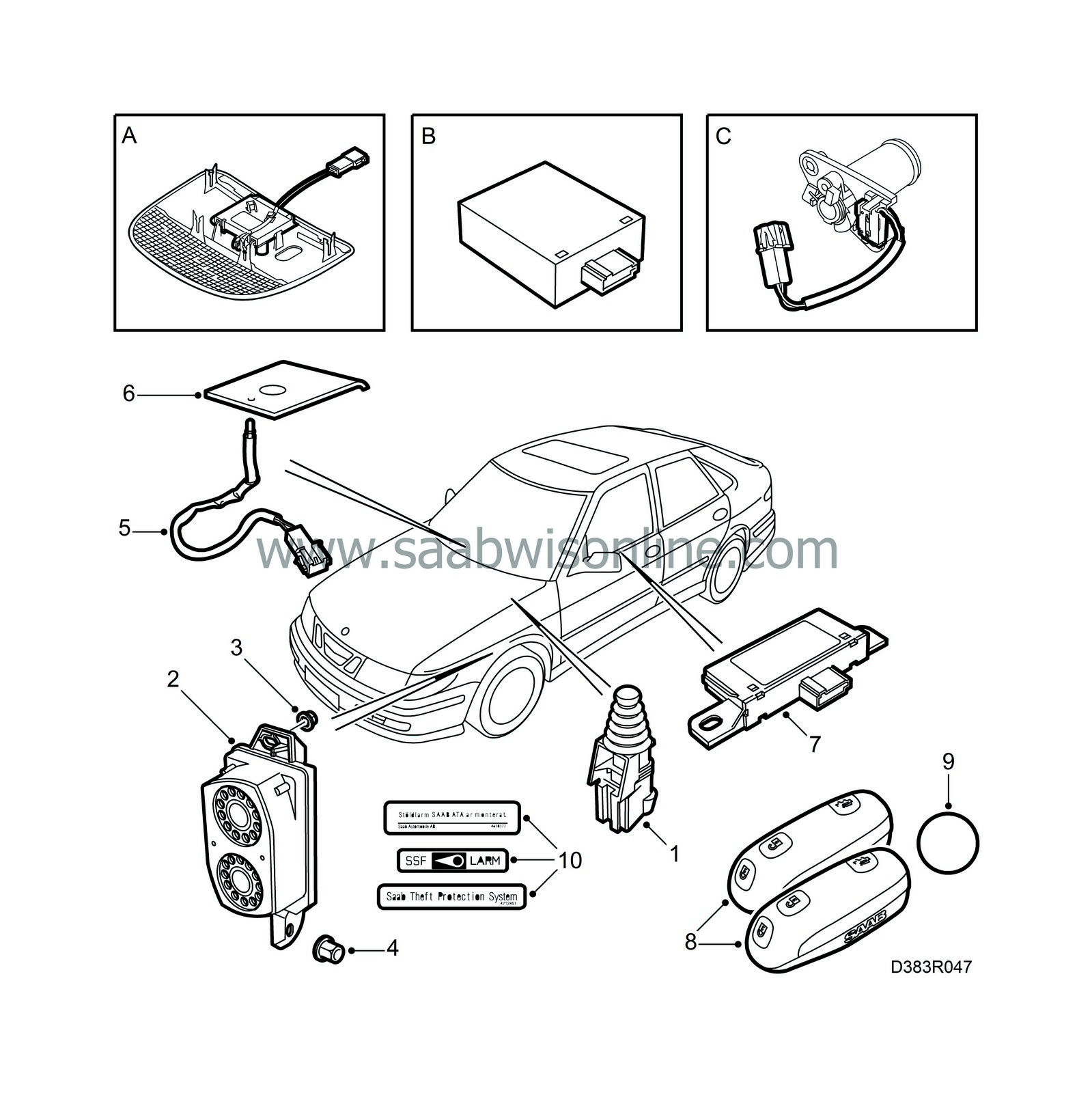
Anti-theft alarm fitting kit components
|
|
Anti-theft alarm fitting kit components
|
Basic kit
|
5.
|
LED (Light Emitting Diode)
|
|
7.
|
Receiver for remote control
|
|
8.
|
Remote controls (2 units)
|
Diverse
|
A.
|
Lens cover with glass breakage sensor
(textile, leather trim, cabin)
|
Labels, decals
The labels and decals should be attached to the side windows and windscreen as described in the instructions in the Service Manual “Group 1 Service” when the anti-theft alarm has been installed and is functioning.

|
1.
|
Open the bonnet and lift up the main fuse box to access the wiring harness with the bonnet switch connector located underneath.
|
|
2.
|
Plug in the wiring harness connector to the bonnet switch.
|
|
3.
|
Fit the bonnet switch into its holder.
|
|
1.
|
Raise the car and remove the front left wheel.
|
|
2.
|
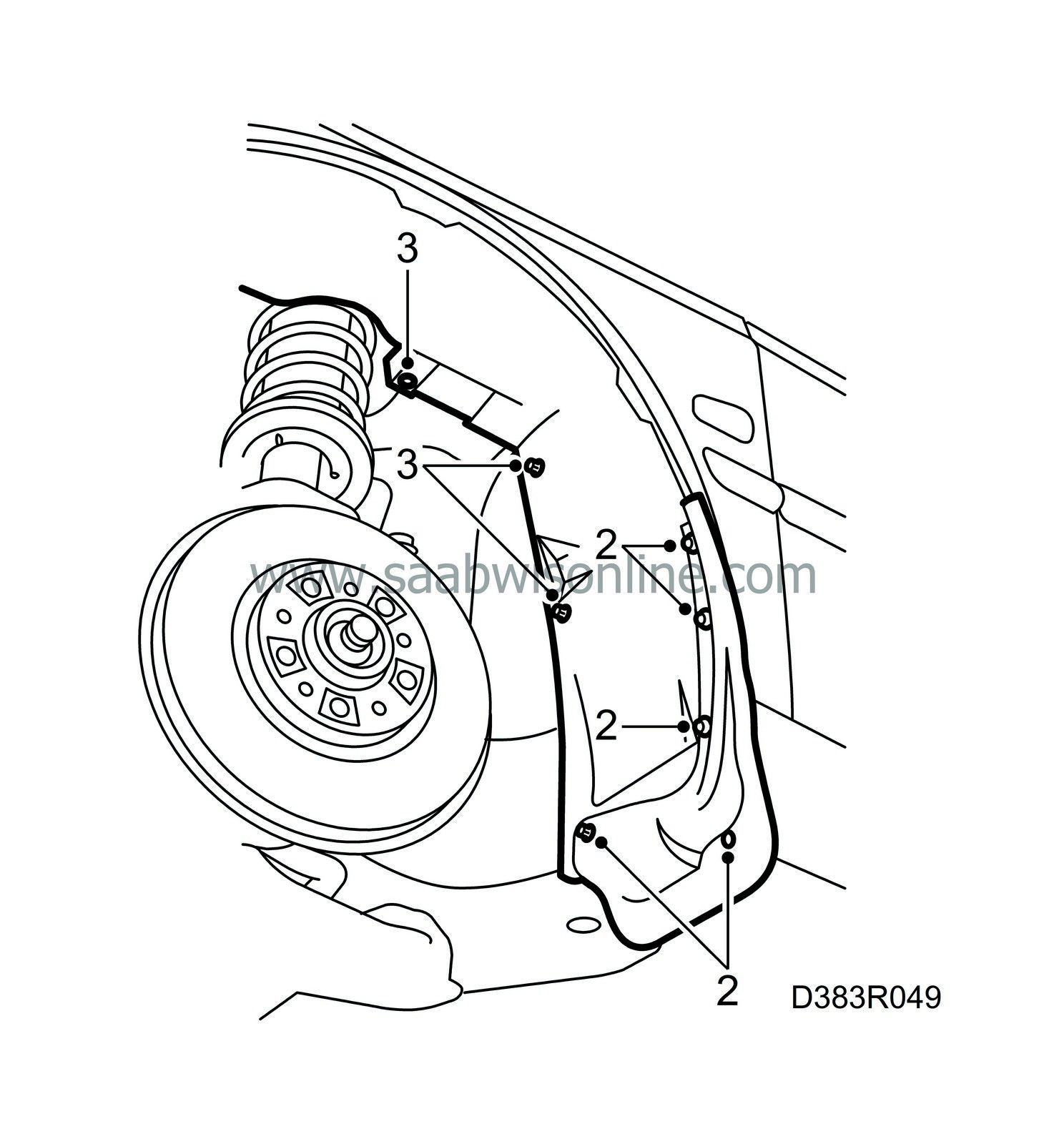
Remove the front left mudflap (4 screws).
|
|
3.
|
Remove the rear section of the wing liner from the left-hand front wheel housing (2 nuts and 1 rivet).
|
|
4.
|
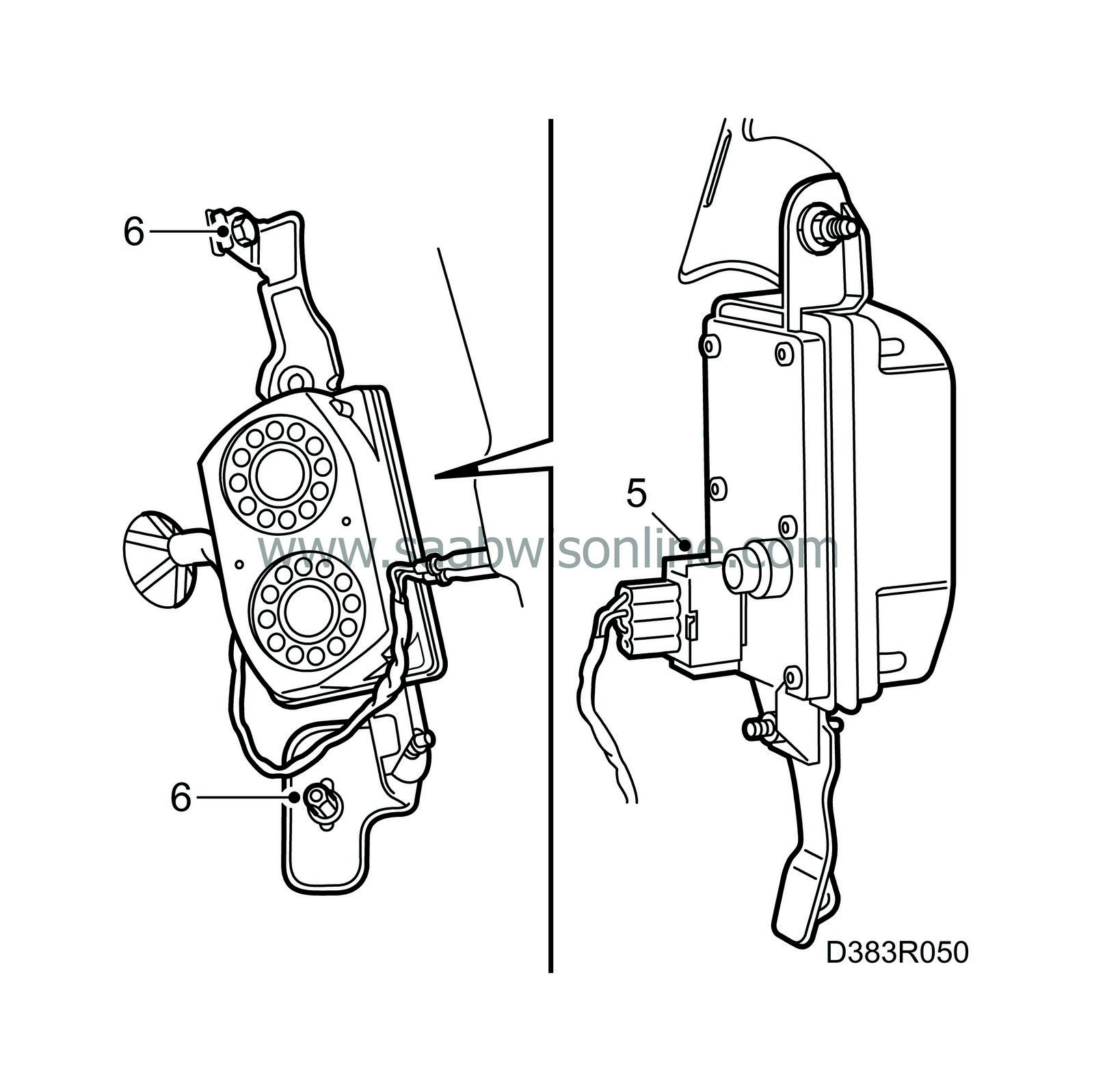
Localize the wiring harness with a 4-pin electrical connector.
|
|
5.
|
Plug the 4-pin connector into the siren.
|
|
6.
|
Fit the siren on the two welded studs and secure it with 2 nuts.
|
|
7.
|
Fit the wing liner, mudflap, and front left wheel, and lower the car to the ground.
|
|
LED (Light Emitting Diode)
|
|
1.
|
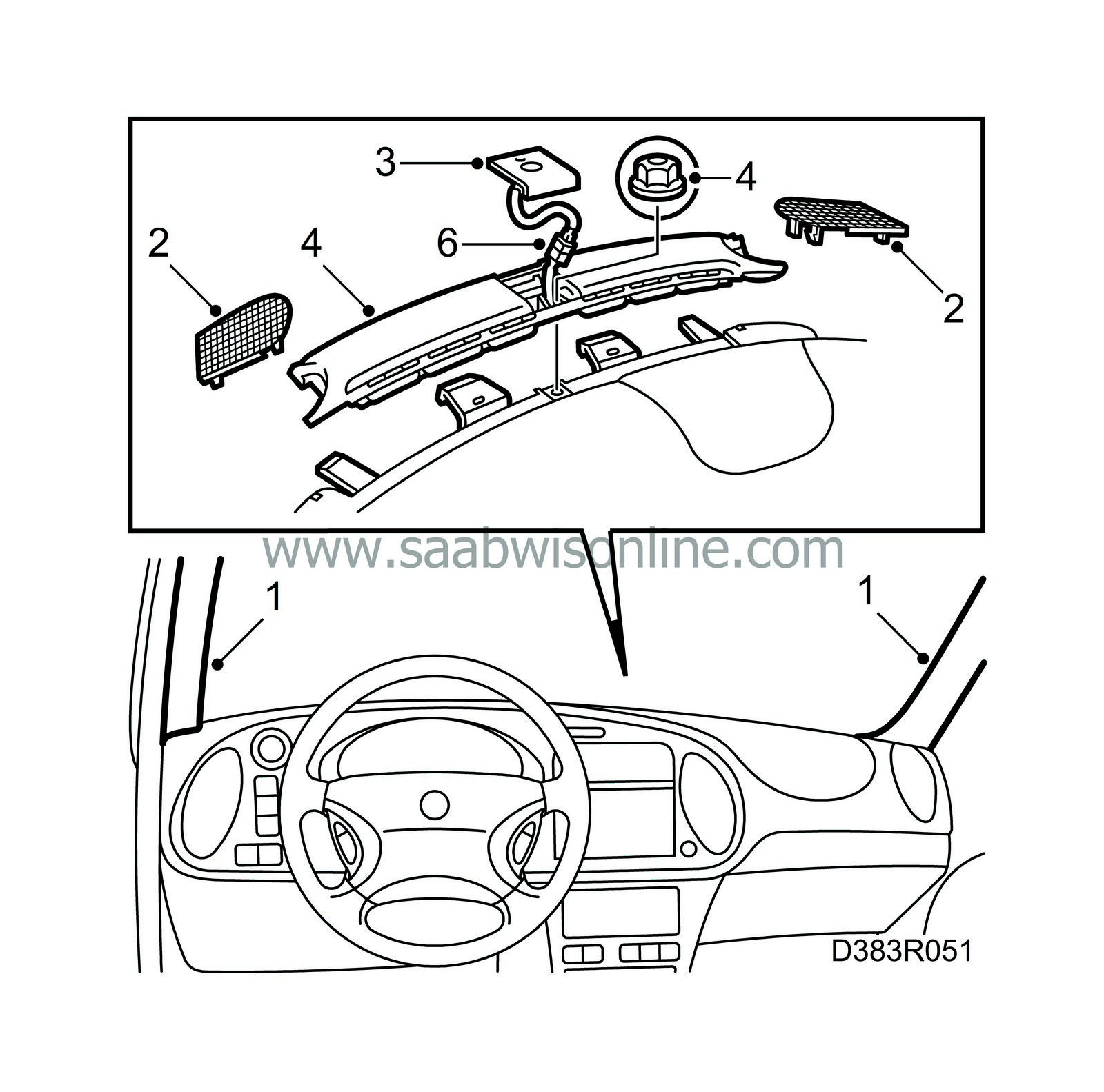
Remove the trim from the A pillar by loosening the rubber strip and pulling off the trim (attached with clips).
|
|
2.
|
Remove the right-hand loudspeaker grille.
|
|
3.
|
In the middle of the defroster cover there is a cover plate. Remove this plate by pressing backwards and lifting slightly.
|
|
4.
|
Remove the defroster cover by loosening the nut and lifting the cover straight upwards at the rear edge (attached with clips).
|
|
5.
|
Localize the electrical connector for the LED.
|
|
6.
|
Fit the LED into the plate included in the kit and attach the connector to the LED. Ensure that the connector is positioned correctly in the appropriate space underneath the defroster cover.
|
|
7.
|
Fit the parts that were removed.
|
|
Receiver for remote control
|
|
Note
|
|
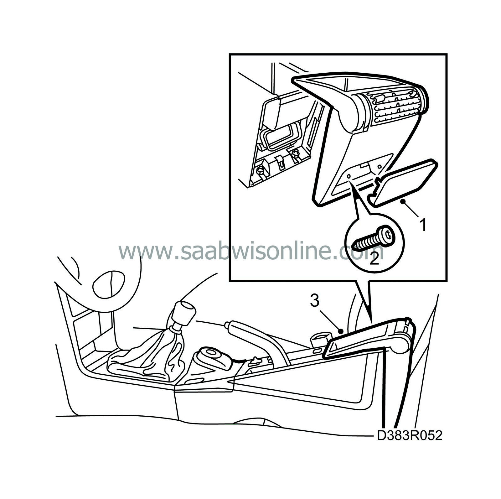
The remote control receiver and the tilt sensor are both situated underneath the floor console. So if a tilt sensor is to be included in the anti-theft alarm, it should be fitted at the same time as the remote control receiver.
|
|
1.
|
Remove the cover for the rear section of the floor console.
|
|
3.
|
Lift off the rear section of the floor console.
|
|
4.
|
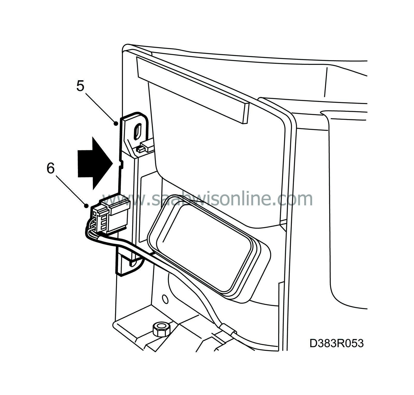
Localize the electrical connector for the receiver.
|
|
5.
|
Fit the receiver into its holder.
|
|
7.
|
Refit the rear section of the floor console.
|
|
1.
|
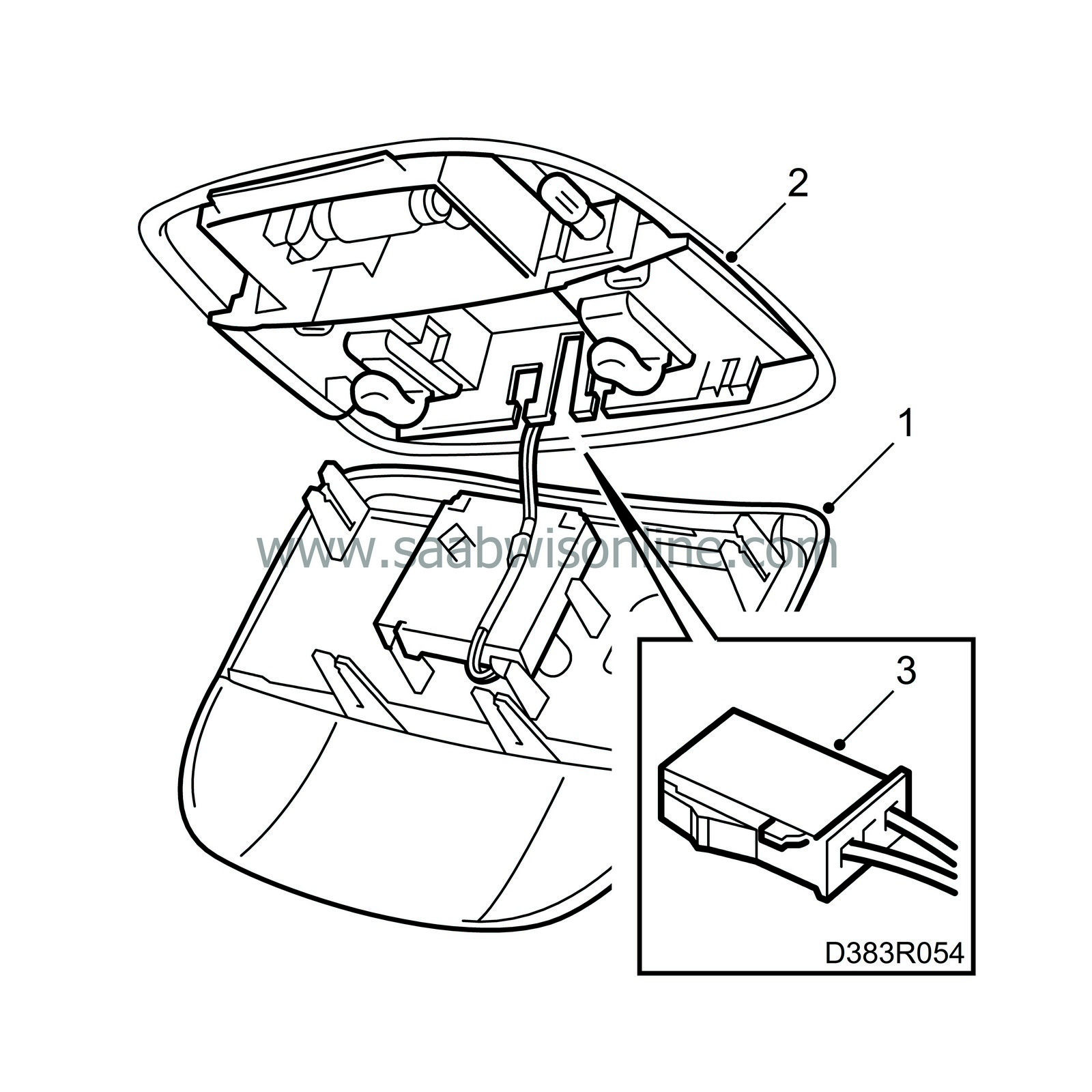
Remove the existing lens cover from the centre roof lamp.
|
|
2.
|
Loosen the switch panel in the lamp to obtain access to the electrical connector for the glass breakage sensor. Pull out the connector and fit the switch panel back in the lamp.
|
|
3.
|
Attach the electrical connector to the glass breakage sensor on the new lens cover.
|
|
4.
|
Press the lens cover into position.
|
|
5.
|
Finally, the glass breakage sensor must be programmed into the theft protection system with the diagnostic tool. If the tilt sensor is also to be fitted, it should be programmed after fitting.

|

|
1.
|
Remove the antenna unit by turning it clockwise. Lift the unit up and disconnect the electrical connector.
|
|
2.
|
Remove the ignition switch cover. Start at the back as it is fastened with hooks at the front.
|
|
3.
|
Unscrew 2 screws holding the floor console.
|
|
4.
|
Remove the rear section of the floor console.
|
|
5.
|
Unscrew 2 nuts holding the floor console.
|
|
6.
|
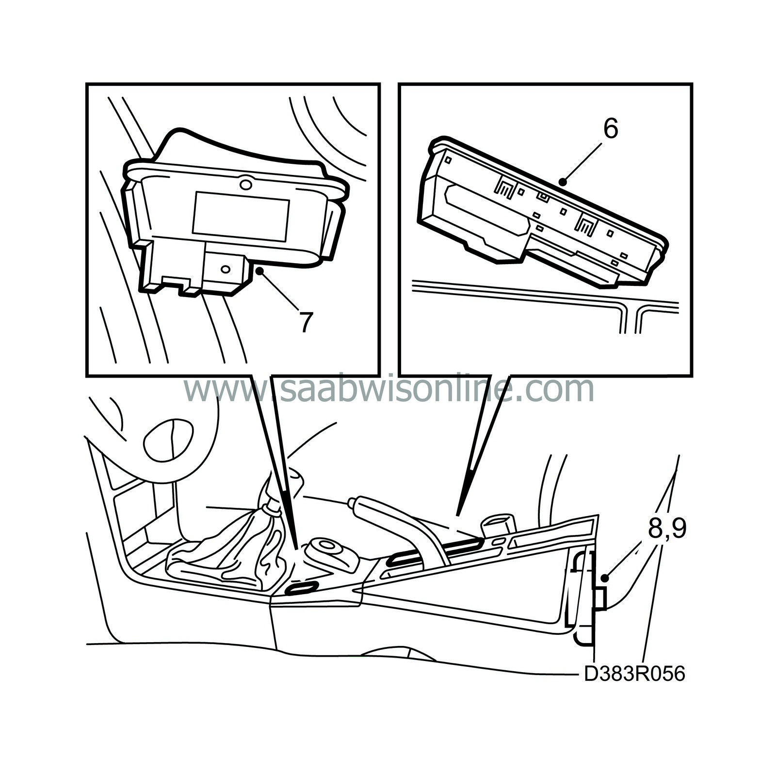
Remove the switch. Start at the front. (Use a suitable screwdriver inserted into the groove in order to press out the front of the switch.)
|
|
7.
|
On the Convertible, remove the interior lighting switch.
|
|
8.
|
Remove the remote control receiver from the side wall of the floor console, if it was fitted earlier.
|
|
9.
|
Disconnect the electrical connector from the receiver unit.
|
|
10.
|
Lift off the floor console.
|
|
11.
|
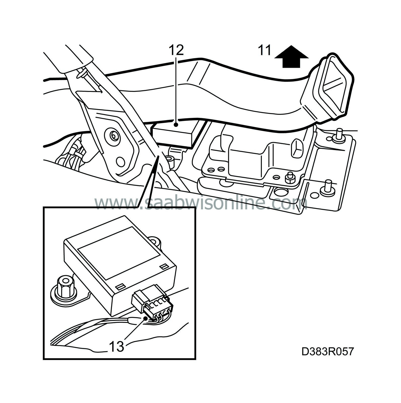
Lift the floor duct. Localize the electrical connector for the tilt sensor on the wiring harness.
|
|
12.
|
Fit the tilt sensor in its holder (slides in). Fit the connector.
|
|
13.
|
Replug the connector.
|
|
14.
|
Fit the remote control receiver.
|
|
15.
|
Fit the parts that were removed.
|
|
16.
|
Finally, the tilt sensor must be programmed into the theft protection system with the diagnostic tool.

|
|
Microswitch in boot lid/tailgate lock (LA)
|
|
1.
|
Open the boot lid/tailgate.
|
|
2.
|
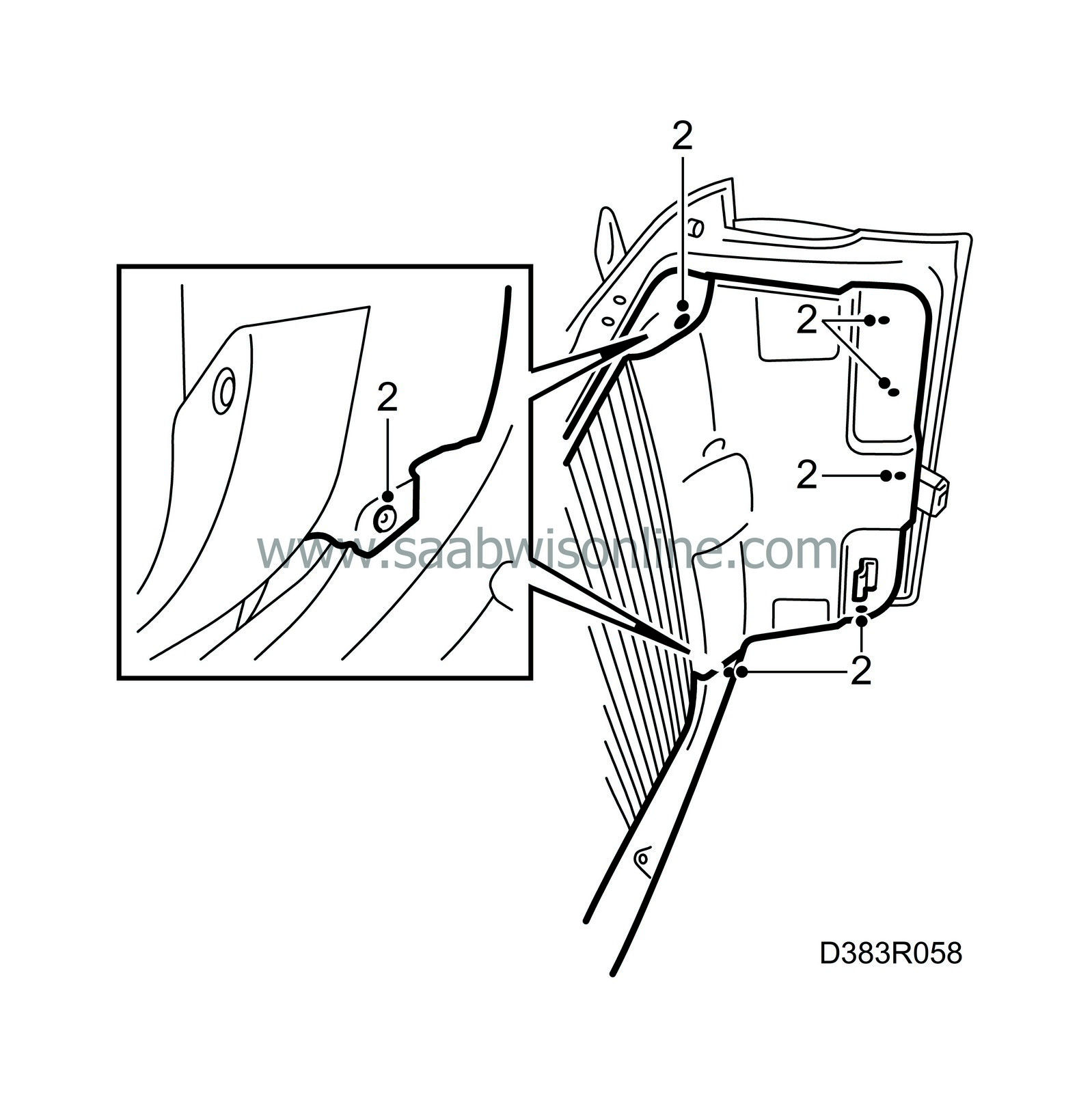
Remove the boot lid/tailgate trim.
See Interior equipment

|
|
3.
|
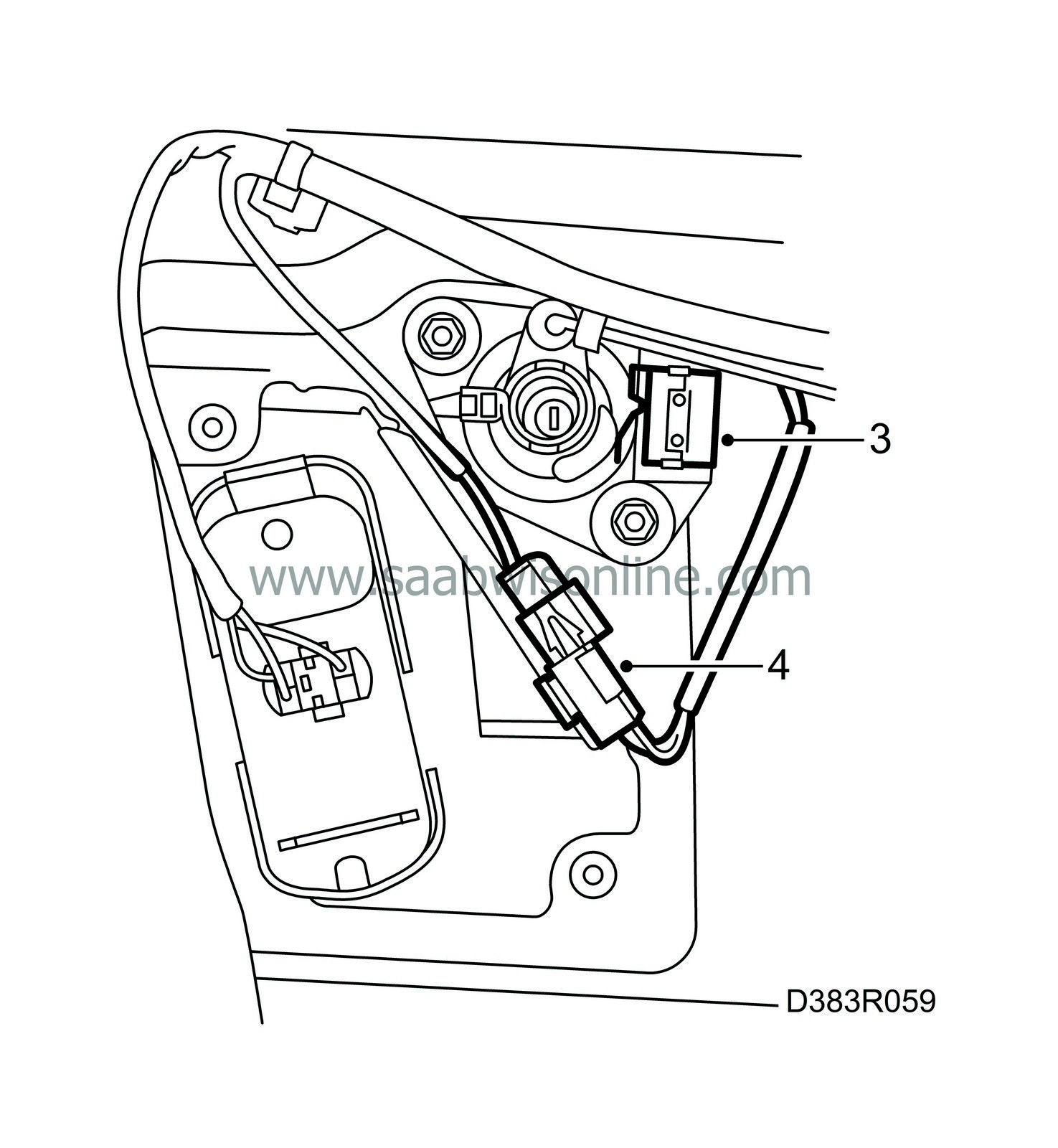
Fit the microswitch.
|
|
4.
|
Localize the electrical connector for the microswitch on the wiring harness and connect it to the microswitch.
|
|
5.
|
Fit the trim on the tailgate.
|


