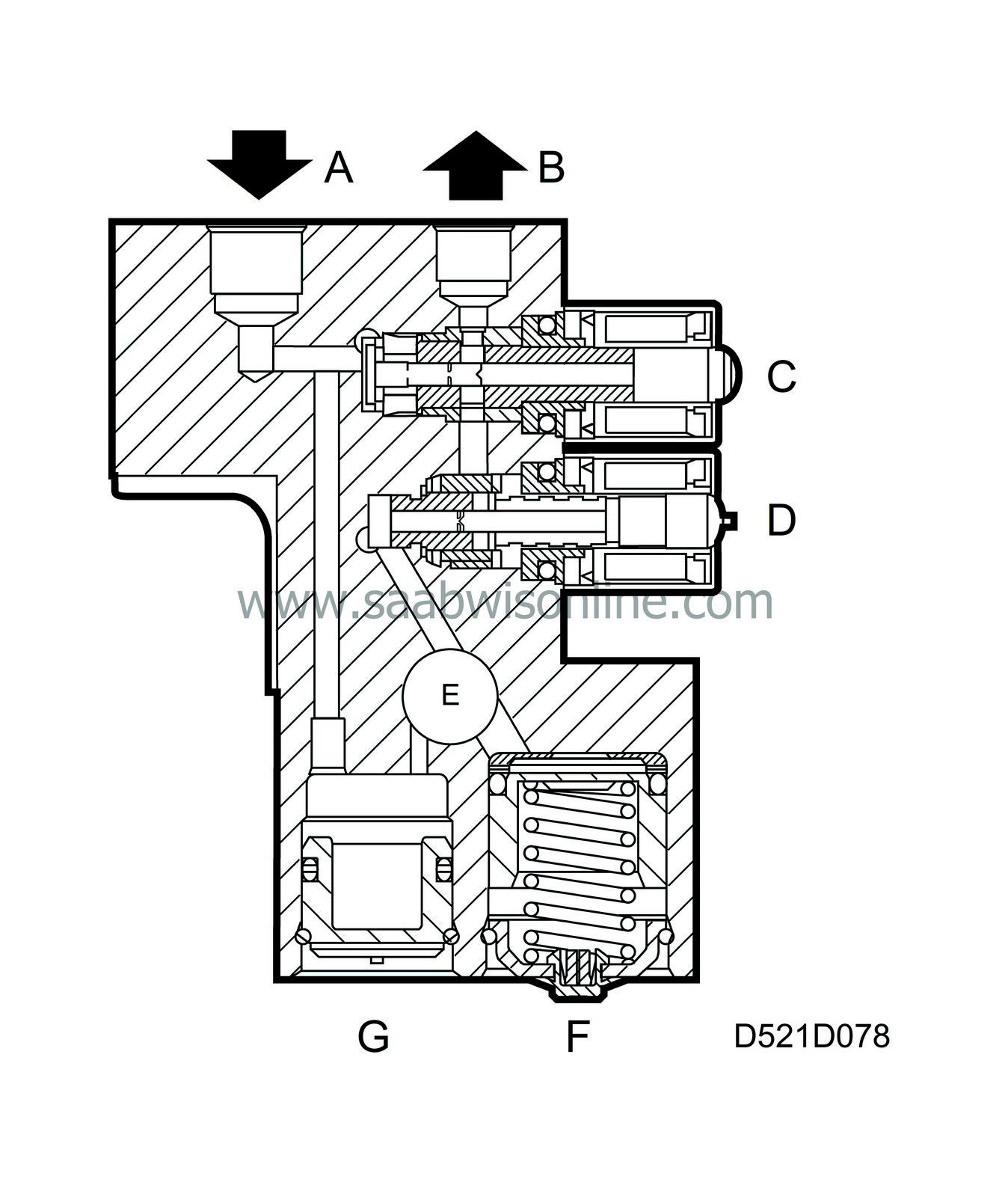
Valve block
| Valve block |
| A. |
To master cylinder
|
|
| B. |
To wheel cylinder
|
|
| C. |
Inlet valve
|
|
| D. |
Outlet valve
|
|
| E. |
Pump
|
|
| F. |
Accumulator chamber
|
|
| G. |
Pressure chamber
|
|
The valve block, which is an integral part of the hydraulic unit, controls the brake pressure to the caliper assemblies during ABS-controlled braking.
The valve block contains eight electromagnetic valves: 4 inlet valves and 4 outlet valves, or 1 inlet and 1 outlet valve per wheel.
In the rest position, the inlet valve is open and the outlet valve closed.
The valve block incorporates an accumulator chamber and a pressure chamber for each brake circuit. The accumulator chamber, which is located between the outlet and the return pump, accumulates the brake fluid until the return pump starts running.
The function of the pressure chamber, which is located between the return pump and master cylinder, is to dampen both noise and pressure fluctuations when the return pump is operating (ABS mode).
The control module performs a valve test each time the ignition is switched on. This test takes place at the same time as the pump-motor test and the valves are actuated for 20 ms.
Diagnosis
A fault in a front left solenoid valve will generate DTC C2450.A fault in a front right solenoid valve will generate DTC C2455.
A fault in a rear left solenoid valve will generate DTC C2415.
A fault in a rear right solenoid valve will generate DTC C2485.
In all cases, the ABS function will be disabled and the ABS lamp, brake fluid warning lamp and central warning lamp will come on.


