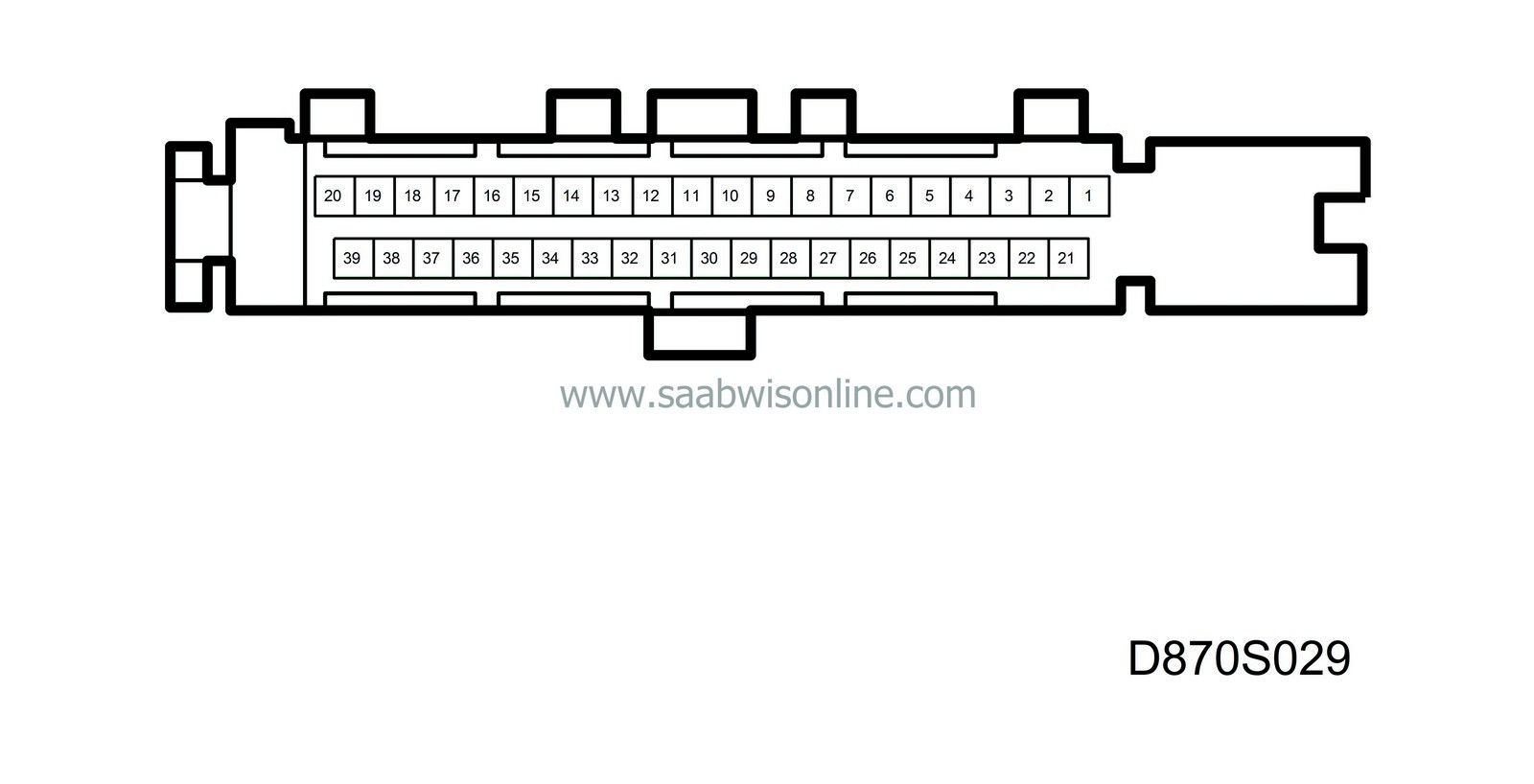
Measurement values, control module connections
| Measurement values, control module connections |
| Keep in mind: |
| • |
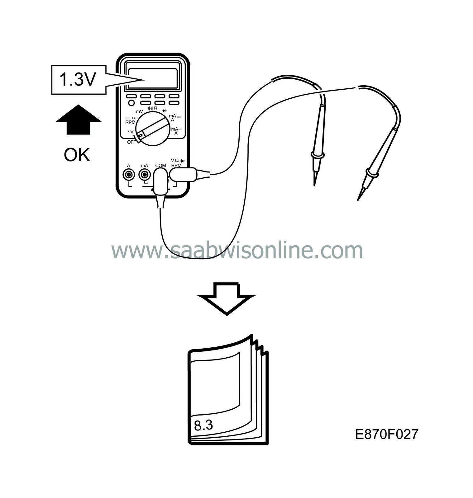
Observe the measurement conditions. Use common sense when considering the test results and measurement values.
|
|
| • |
First, check that the control module is supplied with power and that it is grounded.
Then, check all sensor inputs and signals from other systems. Finally, check the control module outputs. Remember that the measured values do not indicate if the switch works or not. |
|
| • |
If a measured value is incorrect, use the wiring diagram to find out which leads, connectors or components that should be checked further.
|
|
| • |
The indicated values refer to calibrated Fluke 88/97.
|
|
| • |
The measured values indicate the pulse relation and pulse length of the signal. Test instrument with pulse quotient measurement respective pulse width measurement must be used.

|
|
| ACC-unit, control module connections |

|
Pin
|
Lead colour
|
Component/Function
|
In/Out
|
Measuring conditions
|
Measure between
|
Value
|
|
1
|
BK
|
Ground for control module
|
In
|
Ignition ON
|
4-1
|
B+
|
|
2
|
YE
|
Power supply, air recirculation motor
|
Out
|
Activate fresh air
|
2-21
|
+12V
|
|
2, cont'd
|
YE
|
Power supply, air recirculation motor
|
Out
|
Activate air recirculation
|
2-21
|
-12V
|
|
3
|
BN/RD
|
Connection for parking heater
|
In
|
Activate parking heater
|
3-1
|
B+
|
|
4
|
BN/GY
|
Power supply +15
|
In
|
Ignition ON or activated control module
|
4-1
|
B+
|
|
5
|
PK/WH
|
B+ current to fan control module
|
Out
|
Ignition ON
|
5-1
|
B+
|
|
6
|
PK
|
Stepping motor, air-mixing damper
|
Out
|
Ignition ON activate engine
|
6-25
|
50 Hz/50% LP Hi-Lo
|
|
7
|
BN/WH
|
Stepping motor, air-mixing damper
|
Out
|
Ignition ON activate engine
|
7-26
|
50 Hz/50% LP Hi-Lo
|
|
8
|
BU/WH
|
Stepping motor, air distribution damper
|
Out
|
Ignition ON activate engine
|
8-27
|
50 Hz/50% LP Hi-Lo
|
|
9
|
WH
|
Stepping motor, air distribution damper
|
Out
|
Ignition ON activate engine
|
9-28
|
50 Hz/50% LP Hi-Lo
|
|
10-13
|
|
No connection
|
|
|
|
|
|
14
|
GY/RD
|
Fan control module, control current
|
Out
|
Ignition ON change fan speed
|
14-1
|
0-5 V
|
|
15
|
YE/RD
|
Power supply fan, cabin temperature sensor
|
Out
|
Ignition ON
|
15-1
|
B+
|
|
16
|
BN/RD
|
Solar sensor
|
Out
|
Ignition ON
|
16-36
|
0-0.5 V
|
|
17-18
|
|
No connection
|
|
|
|
|
|
19
|
VT
|
Mixed-air temperature sensor
|
In
|
Ignition ON
|
19-38
|
see Technical data
|
|
20
|
BU/YE
|
Cabin temperature sensor
|
In
|
Ignition ON
|
20-39
|
see Technical data
|
|
21
|
RD
|
Power supply, air recirculation motor
|
Out
|
Activate air recirculation
|
2-21
|
LHD: -12 V
RHD: +12 V |
|
21, cont'd.
|
RD
|
Power supply, air recirculation motor
|
Out
|
Activate fresh air
|
2-21
|
LHD: +12 V
RHD: -12 V |
|
22
|
RD/WH
|
Power supply +30
|
In
|
Power supply +30
|
22-1
|
B+
|
|
23
|
|
No connection
|
|
|
|
|
|
24
|
BN/GY
|
Shut-off valve, heater box
|
Out
|
Ignition ON max cooling -LO
|
4-24
|
B+
|
|
25
|
BU/GN
|
Stepping motor, air-mixing damper
|
Out
|
Ignition ON activate engine
|
25-6
|
50 Hz/50% LP Hi-Lo
|
|
26
|
OG
|
Stepping motor, air-mixing damper
|
Out
|
Ignition ON activate engine
|
26-7
|
50 Hz/50% LP Hi-Lo
|
|
27
|
GN/WH
|
Stepping motor, air distribution damper
|
Out
|
Ignition ON activate engine
|
27-8
|
50 Hz/50% LP Hi-Lo
|
|
28
|
BN
|
Stepping motor, air distribution damper
|
Out
|
Ignition ON activate engine
|
28-9
|
50 Hz/50% LP Hi-Lo
|
|
29-32
|
|
No connection
|
|
|
|
|
|
33
|
GN
|
I-bus (+)
|
In/Out
|
Ignition ON
|
33-1
|
2-3 V
|
|
34
|
WH
|
I-bus (-)
|
In/Out
|
Ignition ON
|
34-1
|
2-3 V
|
|
35
|
|
No connection
|
|
|
|
|
|
36
|
YE/GN
|
Solar sensor ground
|
Out
|
Ignition ON
|
16-36
|
0-0.5 V
|
|
37
|
|
No connection
|
|
|
|
|
|
38
|
BU/RD
|
Air-mixing temperature sensor, ground
|
Out
|
Ignition ON
|
38-19
|
see Technical data
|
|
39
|
YE/BN
|
Cabin temperature sensor, sensor ground
|
Out
|
Ignition ON
|
39-20
|
see Technical data
|


