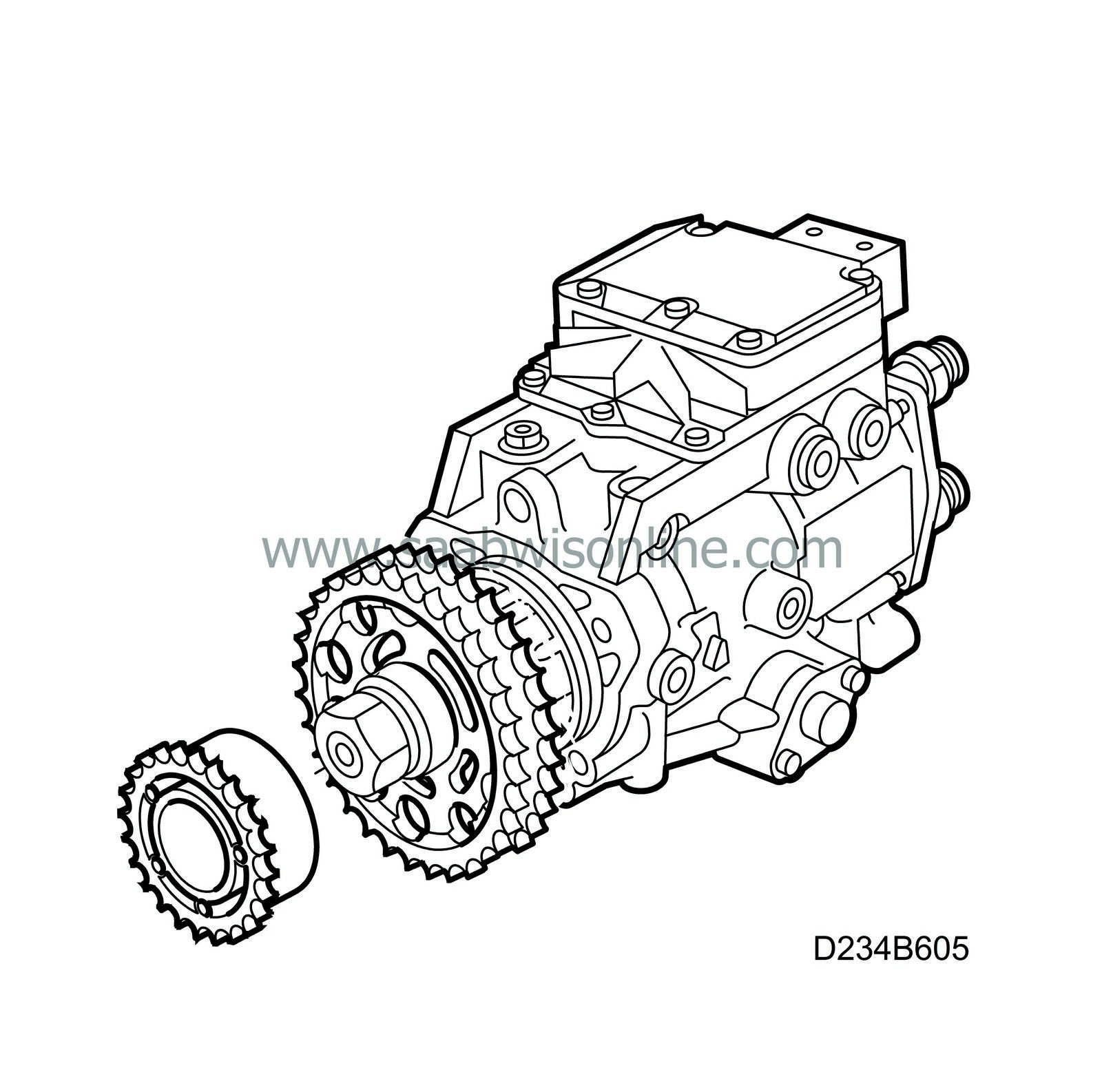
(234-2278) Faulty sprocket, diesel pump
|
MODIFICATION INSTRUCTION
|
|
Bulletin Nbr:
|
234-2278
|
|
Date:
...........
|
december 2000
|
|
Market:
|
enligt lista
|
|
|
Faulty sprocket, diesel pump
|
Cars in stock must be remedied before delivery.
A personal communication must be sent to the owners of cars already delivered requesting them to get in touch with the nearest Saab garage as soon as possible to have the fault rectified.
Saab 9-3 M01 with diesel engine and one of the following chassis numbers
12020040 12020490 12020494 12020498 12020503 12020506 12020554 12020569 12020583 12020602 12020606 12020612 12020624 12020628 12020633 12020637 12020642 12020650 12020670 12020674 12020678 12020681 12020682 12020686 12020690 12020694 12020698 12020702 12020706 12020714 12020719 12020726 12020736 12020741 12020755 12020760 12020795 12020798 12020818 12020830 12020833 12020837 12020844 12020848 12020854 12020917 12020920 12020923 12020926 12020932 12020957 12021450 12021454 12021457 12021460 12021464 12021468 12021475 12021478 12021493 12021496 12021499 12021546 12021557 12022714 12023074 12026002
A material fault has been identified in a limited number of sprockets on the diesel engine's fuel distribution pump. The useful life of the sprocket can be reduced thus necessitating this exchange.
95 44 073 Sprocket
95 44 099 Cover
95 44 297 Screw
46 23 286 Gasket
95 44 420 Gasket (x2)
(16) 87 81 841 Silicone Flange Seal
(16) 30 20 971 Molycote 1000
Examine box A2 on the modification identity plate before proceeding. Continue as follows if the box is not marked:
|
1.
|
Make note of the radio code if needed, place the car on a hoist, use a wing protector and remove the battery's negative cable.
|
|
2.
|
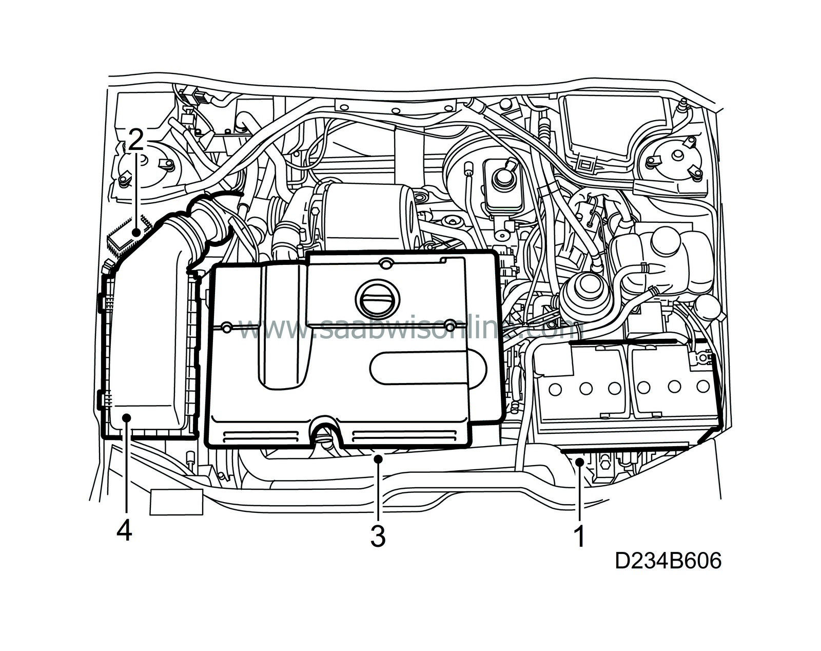
Remove the diesel engine's relay.
|
|
3.
|
Remove the engine cover.
|
|
4.
|
Remove the air cleaner, with the mass air flow sensor and hoses, from the turbocharger and the valve cover.
|
|
5.
|
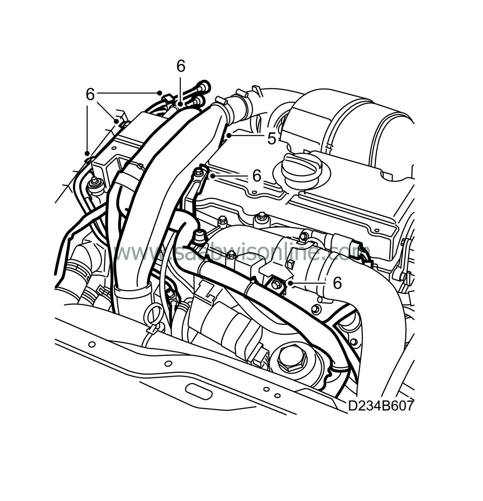
Remove the turbocharger pressure pipe (2 screws under the wiring harness). Plug the turbo intake and turbo hoses.
|
|
6.
|
Remove the wiring harness's channel from the cylinder head and loosen the fuel lines from the clip on the valve cover.
|
|
7.
|
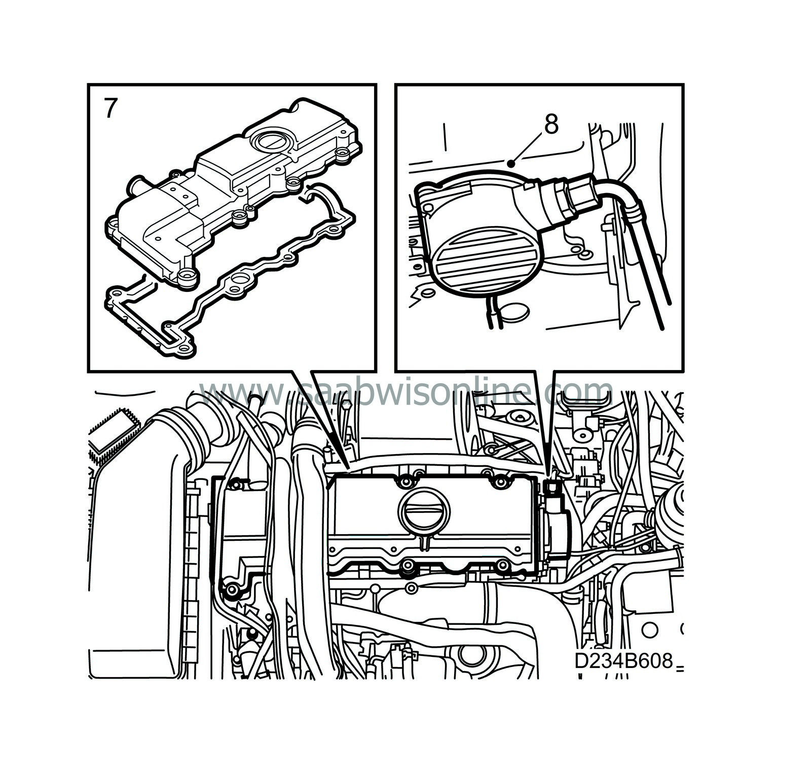
Remove the valve cover.
|
|
8.
|
Remove the vacuum pump's four retaining screws and twist the pump to the side.
|
|
9.
|
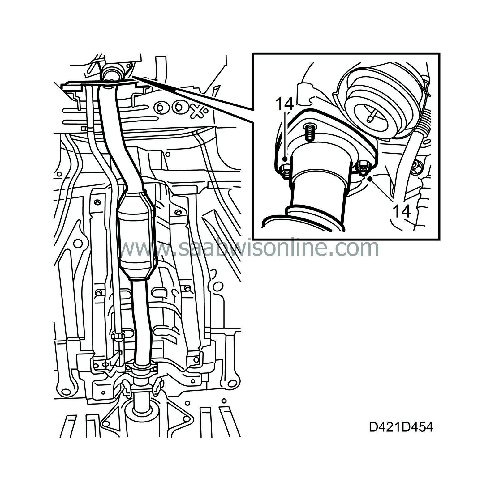
Remove the rear nut from the forward exhaust pipe's connection to the turbocharger.

|
|
10.
|
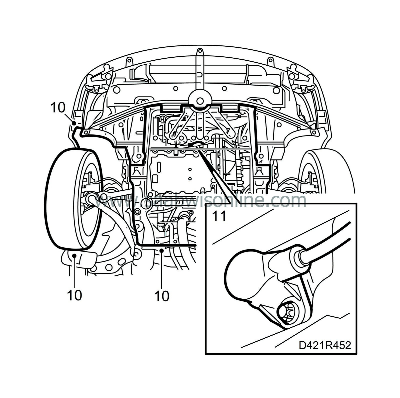
Lift the car, remove the right front wheel, the lower engine cover and the cover in the right wheel housing.
|
|
11.
|
Remove the crankshaft sensor and the O-ring.
|
|
12.
|
Remove tension from the belt tensioner by twisting it counter-clockwise (towards the rear of the car) using a 19 mm wrench and lift off the belt.

|
|
13.
|
Remove the belt tensioner.
|
|
14.
|
Loosen the nuts to the forward part of the exhaust pipe from the turbocharger.
|
|
15.
|
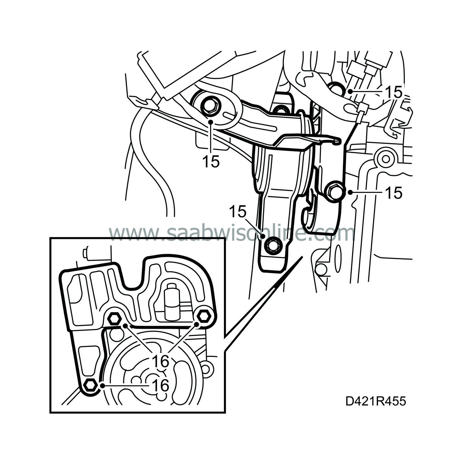
Lower the car and place a jack with a block of wood under the right side of the oil sump. Lift the engine until the right engine mounting is unloaded and remove the right engine mounting.
|
|
16.
|
Remove the engine mount and bracket (the lower screw need not be completely removed) and lift the engine a bit further.
|
|
17.
|
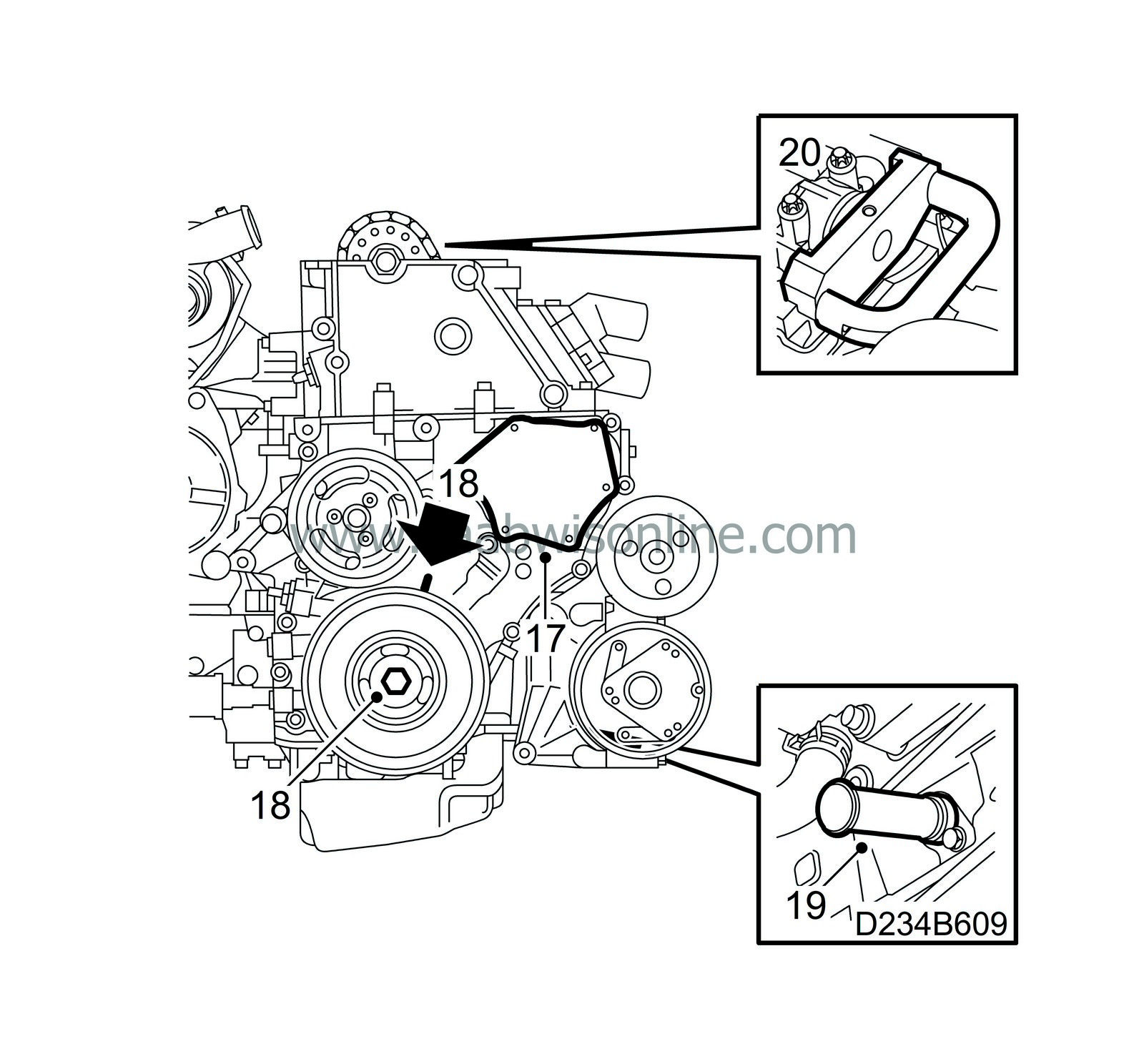
Remove the cover plate screws, carefully insert a putty knife behind the cover and carefully pry it loose.
|
|
18.
|
Twist the crankshaft with the help of the belt pulley's central screw to just before the mark for top dead centre in cylinder 1. Make sure that both camshaft lobes for cylinder 1 point upwards.
|
|
19.
|
Insert inspection gauge 83 95 352 in the hole for the crankshaft sensor. Push the tool somewhat inward at the same time as the crankshaft is twisted to the zero point. The tool will then go into an outlet in the crankshaft and lock it.
|
|
20.
|
Insert inspection gauge 83 95 386 into the camshaft and cylinder head.
|
|
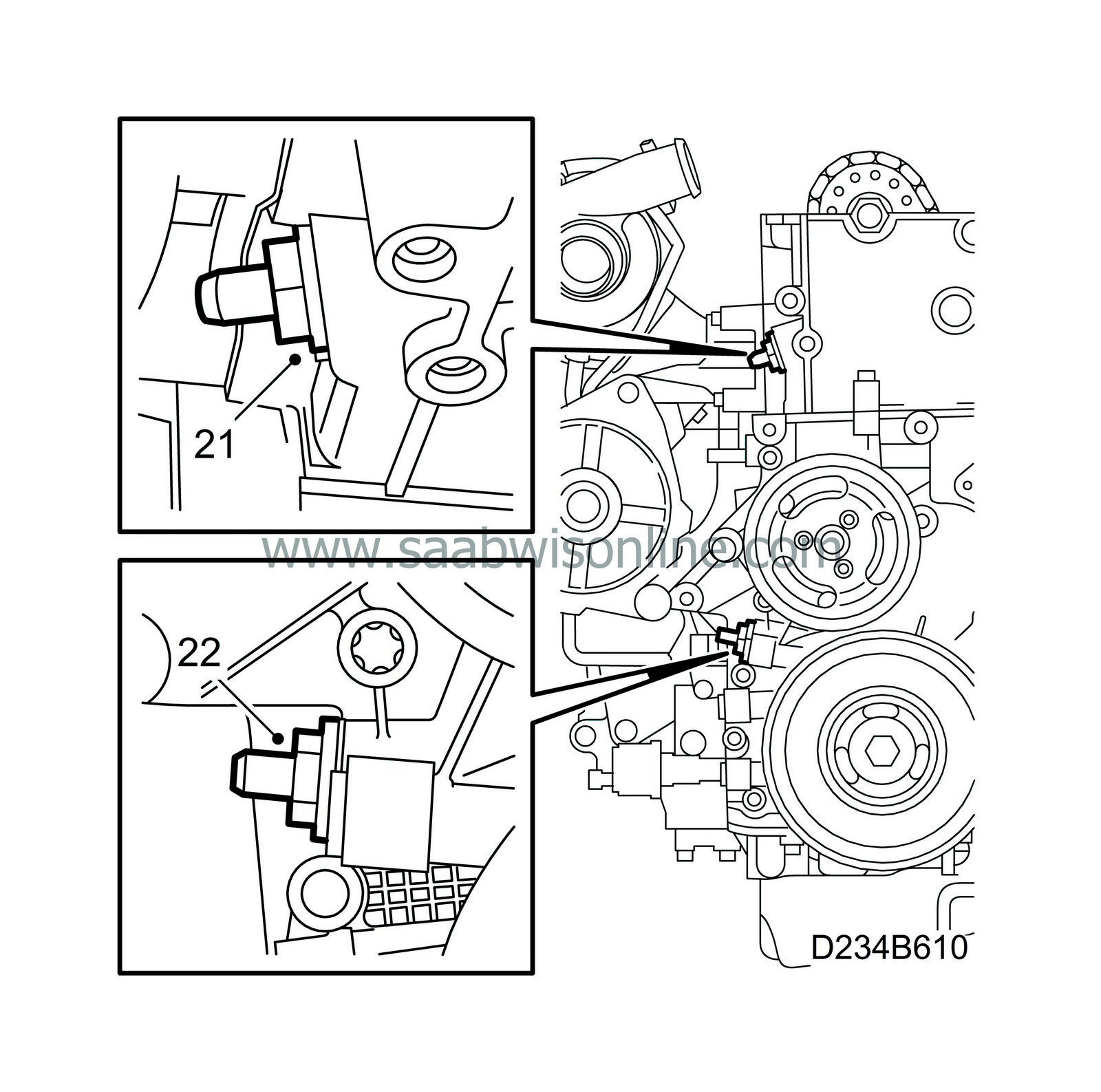
21.
|
Remove the upper timing chain tensioner. Note how it is assembled. Upper and lower chain tensioners may not be switched.
|
|
22.
|
Remove the lower timing chain tensioner.
|
|
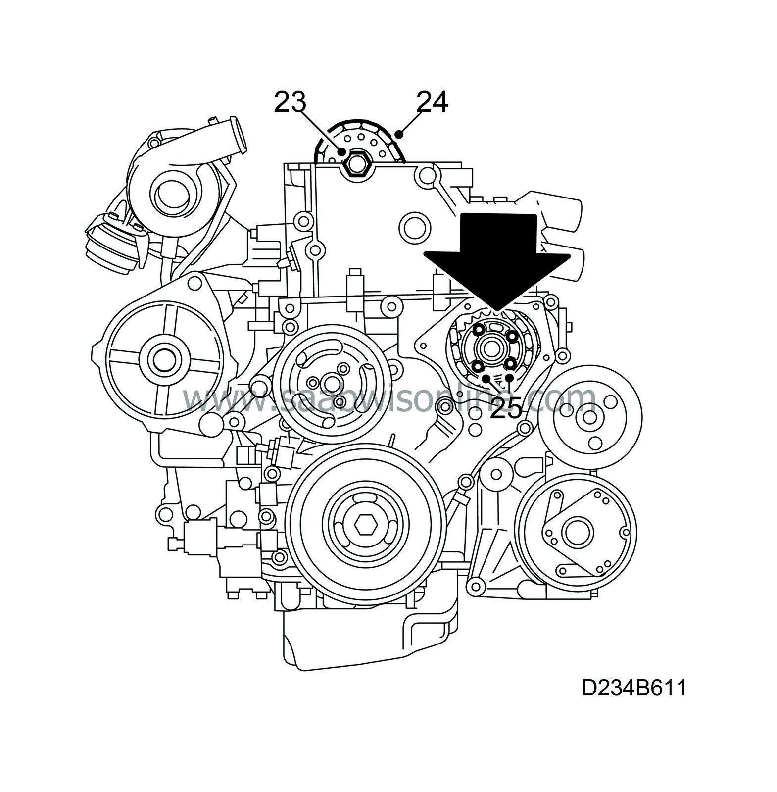
23.
|
Remove the camshaft sprocket. Use an open wrench as a support in the six-sided outlet on the camshaft.
|
|
24.
|
Take away the camshaft sprocket and fasten the chain with a tiewrap, so that it won't fall down.
|
|
25.
|
Loosen the four screws for the fuel distributor pump's sprocket and remove the sprocket. Make a note of the sprocket's position using the arrow as a reference.
|
|
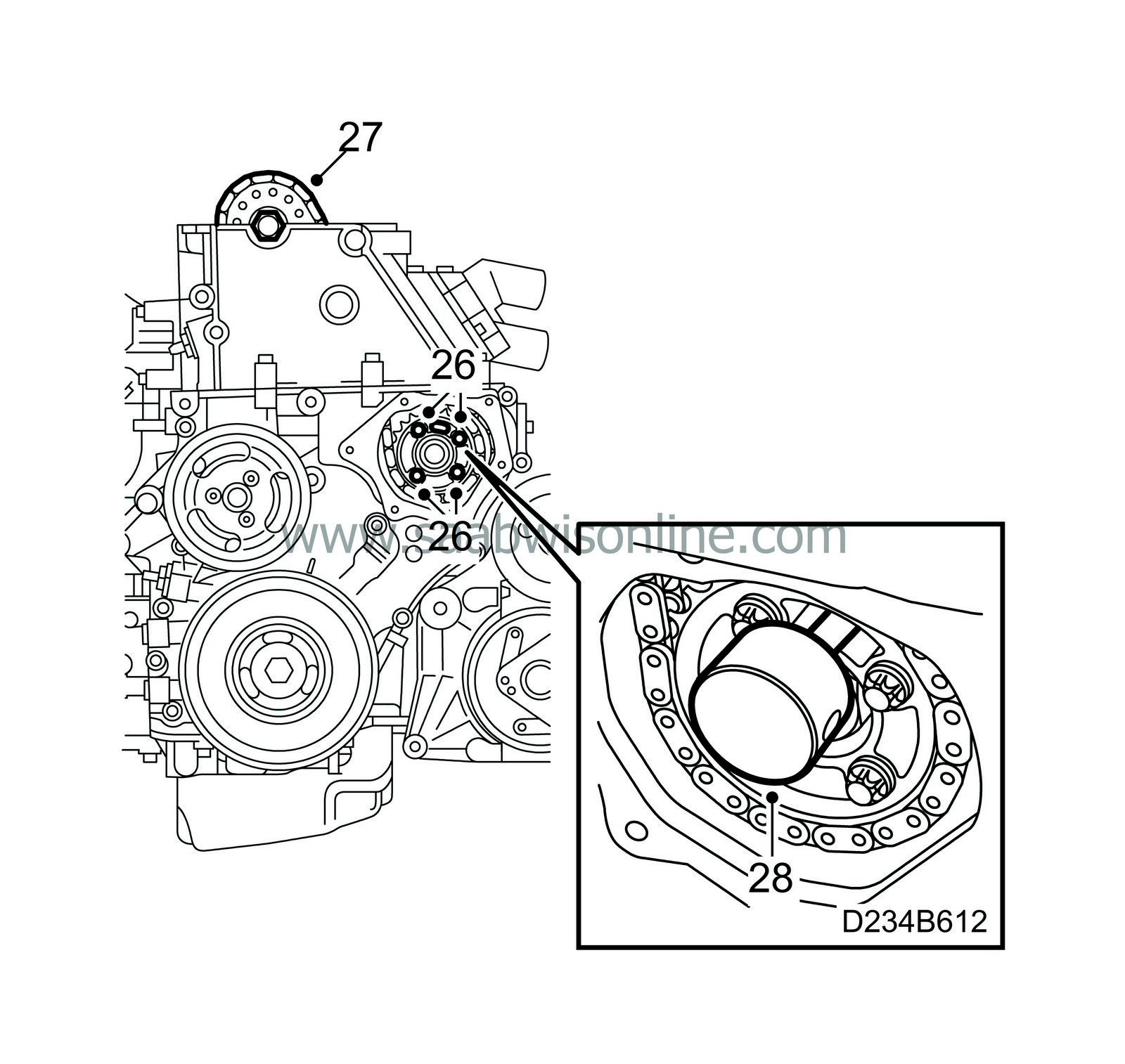
26.
|
Insert the chain along with the fuel distribution pump's new sprocket and hand-tighten the sprocket's screws.
|
|
27.
|
Place the camshaft sprocket underneath the chain and place it onto the camshaft. Mount a new screw and tighten it by hand.
|
|
28.
|
Insert the Installation tool, fuel pump 83 95 337 in the fuel distribution pump's outlet.
|
|
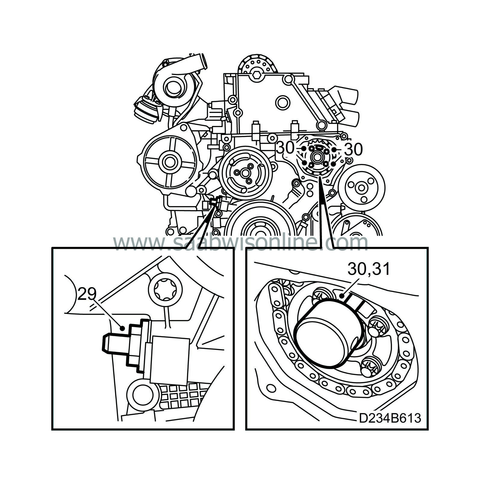
29.
|
Replace the chain tensioner for the lower timing chain using a new gasket.
Tightening torque 60 Nm (44 lbf ft).
|
|
30.
|
Remove the inspection gauge from the fuel distribution pump and tighten the sprocket's screws.
Tightening torque 30 Nm (22 lbf ft).
|
|
31.
|
Re-insert inspection gauge 83 95 337 into the fuel distribution pump's outlet.
|
|
32.
|
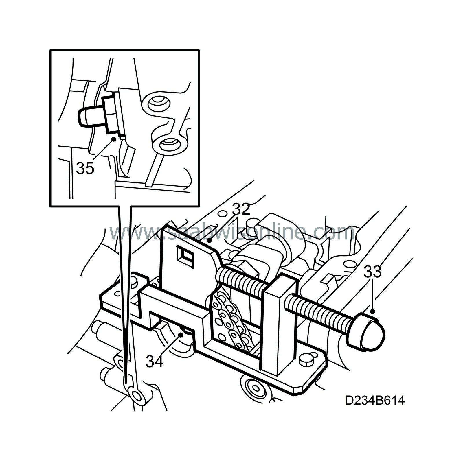
Mount the adapter for the Adjustment tool, cam chain 83 95 394 on the camshaft sprocket and mount the adjustment tool on the cylinder head.
|
|
33.
|
Fix the position for the adapter on the camshaft sprocket by lightly twisting it counter-clockwise with a ratchet handle. Pull on the adjustment screw on the tool.
|
|
34.
|
Tighten the screw for the camshaft sprocket. Support the camshaft using an open-ended wrench on the six-sided fitting on the camshaft.
Tightening torque 90 Nm (67 lbf ft) + 60°
|
|
35.
|
Replace the chain tensioner for the upper timing chain using a new gasket.
Tightening torque 60 Nm (44 lbf ft).
|
|
36.
|
Remove all tools and gauges.
|
|
37.
|
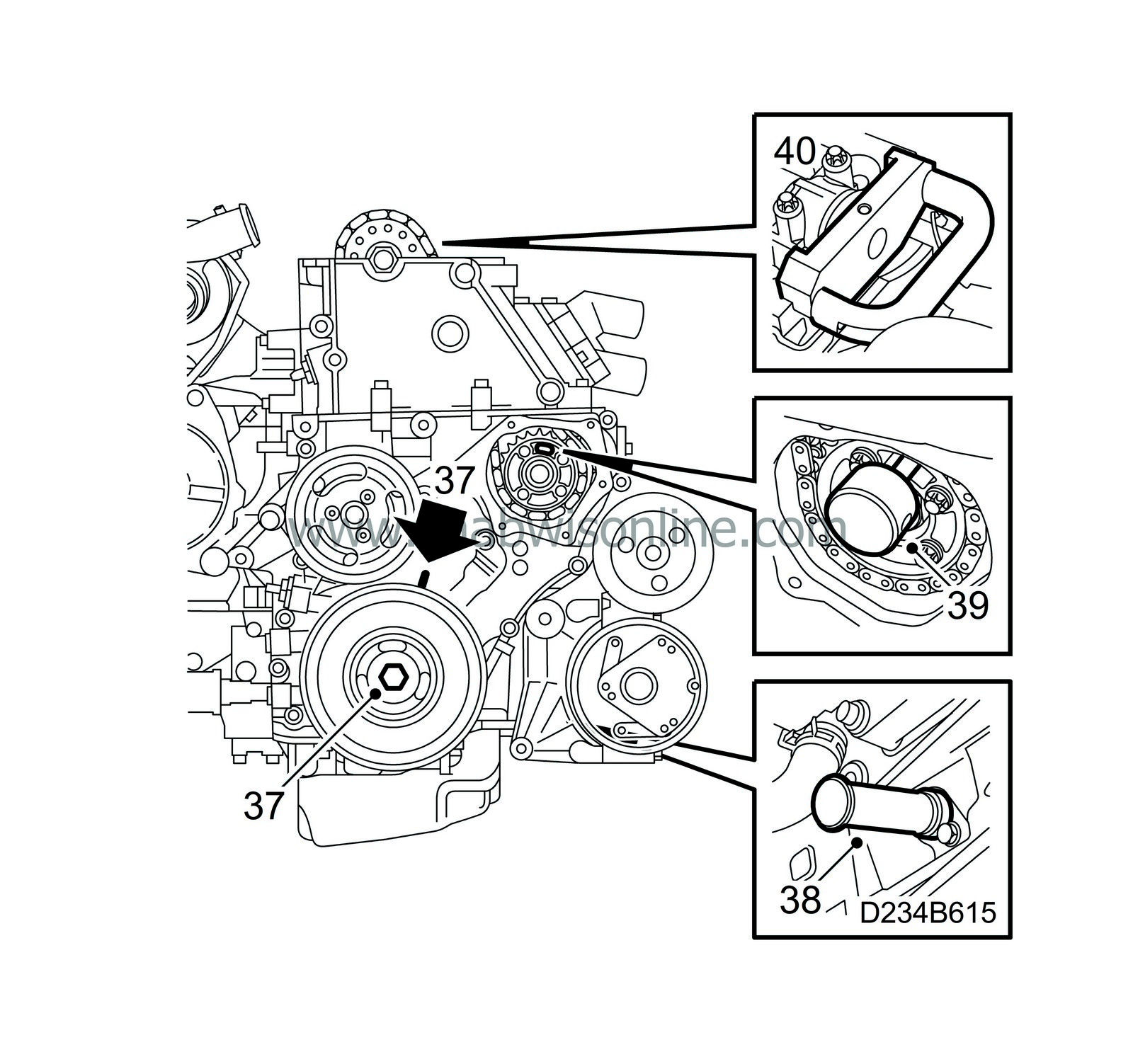
Twist the crankshaft with the help of the belt pulley's central screw to just before the mark for top dead centre in cylinder 1. Make sure that both camshaft lobes for cylinder 1 point upwards.
|
|
38.
|
Insert inspection gauge 83 95 352 in the hole for the crankshaft sensor. Push the tool somewhat inward at the same time as the crankshaft is twisted to the zero point. The tool will then go into an outlet in the crankshaft and lock it.
|
|
39.
|
Insert the Installation tool, fuel pump 83 95 337 in the fuel distribution pump's outlet.
|
|
40.
|
Insert the Positioning tool, camshaft 83 95 386 into the camshaft and cylinder head.
|
|
41.
|
Remove all inspection gauges.
|
|
42.
|
Cover the opening in the timing cover with a lint-free rag and clean any left-over gasket material from the sealing surfaces.
|
|
43.
|
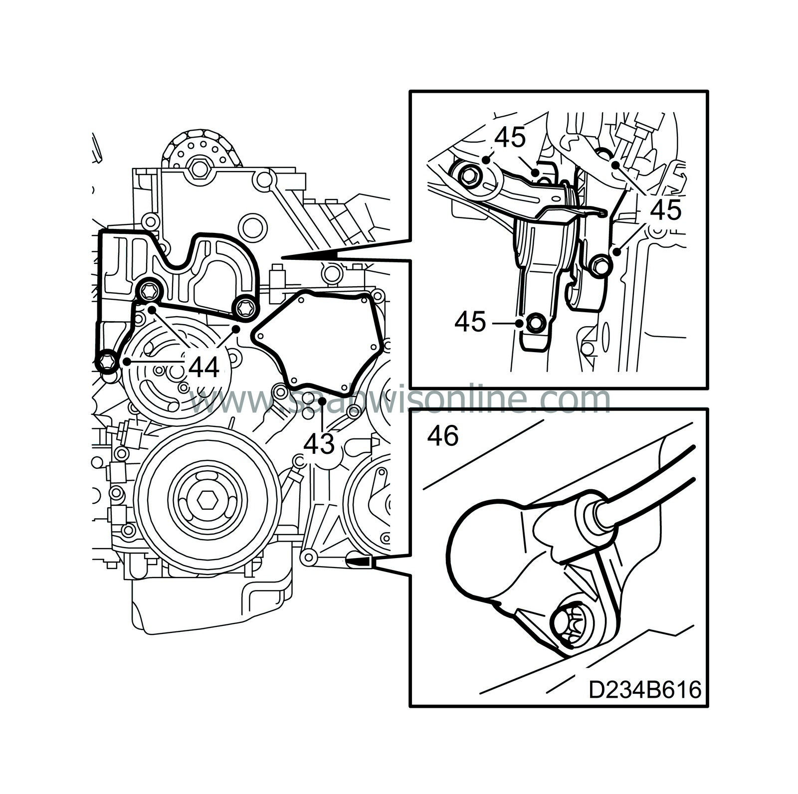
Apply an approximately 2 mm thick line of silicone sealant, part no. 87 81 841 on the cover plate, remove the rag from the timing cover and replace the cover plate.
Tightening torque 6 Nm (4 lbf ft).
|
|
44.
|
Replace the right engine mounting bracket on the engine and tighten the engine mounting against the engine.
Tightening torque 47 Nm (35 lbf ft).
|
|
45.
|
Lower the engine and tighten the right engine mounting. Make sure that nothing is pinched or injured.
Tightening torque 47 Nm (35 lbf ft).
|
|
46.
|
Lift the car and replace the camshaft sensor.
Tightening torque 8 Nm (6 lbf ft).
|
|
47.
|
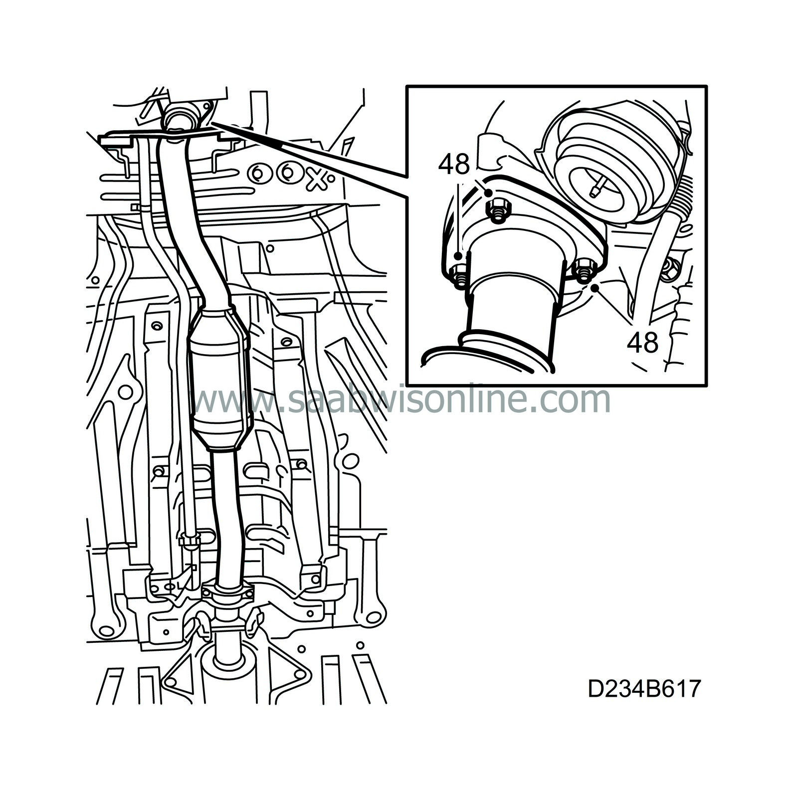
Spread Molycote 1000 on the turbocharger studs, insert the forward portion of the exhaust pipe with a new gasket and thread on new nuts.
|
|
48.
|
Tighten the forward exhaust pipe to the turbocharger.
Tightening torque 25 Nm (19 lbf ft).
|
|
49.
|
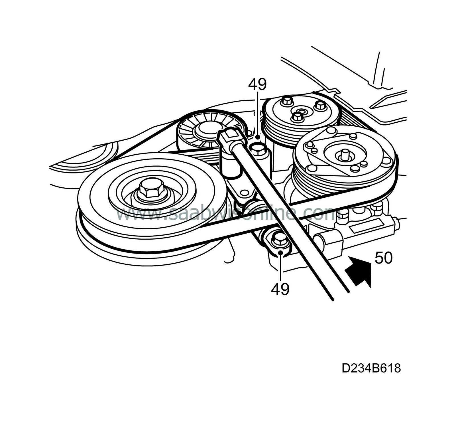
Replace the belt tensioner and tighten first the upper screw, then the lower one.
Tightening torque, upper screw 42 Nm (31 lbf ft).
Tightening torque, lower screw 23 Nm (17 lbf ft).
|
|
50.
|
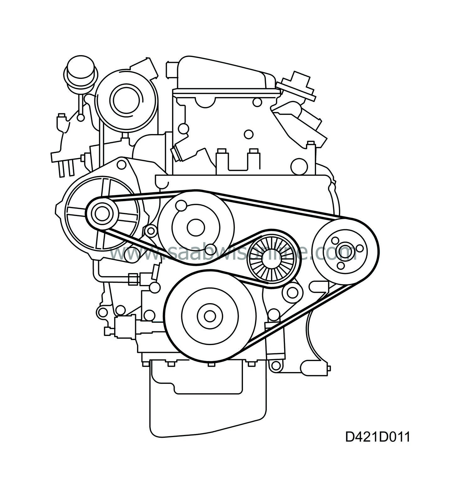
Thread the Poly-V belt around all of the pulleys. Remove tension from the belt tensioner by twisting it counter-clockwise (towards the rear of the car) using a 19 mm wrench and place the belt on the belt tensioner pulley. Check the belt's position on all of the pulleys.
|
|
51.
|
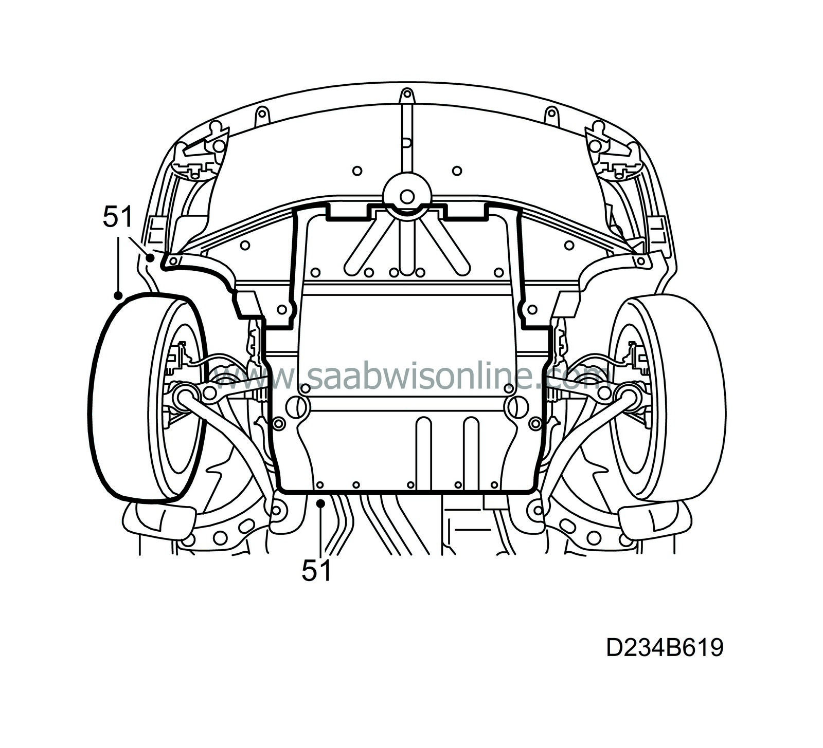
Replace the lower engine cover, the cover in the right wheel housing and the wheel.
Tightening torque, wheel 110 Nm (81 lbf ft).
Lower the car to the floor.
|
|
52.
|
Place a new gasket on the vacuum pump and replace the pump along with the adapter.
Tightening torque 8 Nm (6 lbf ft).
|
|
53.
|
Clean any left-over gasket material from the sealing surfaces.
|
|
54.
|
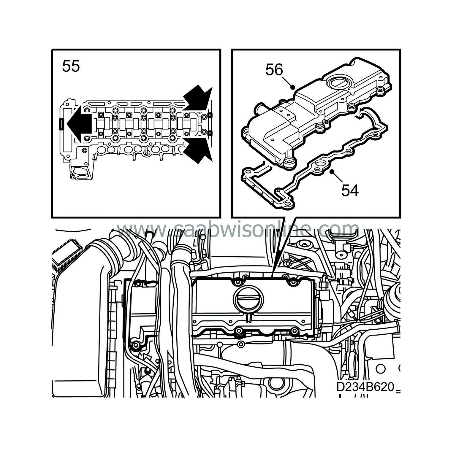
Place the gasket on the valve cover. The screws have sleeves where the gasket shall be placed.
|
|
55.
|
Apply sealant 87 81 841 to the sealing surfaces, see picture.
|
|
56.
|
Place the valve cover on the cylinder head and tighten the screws.
Tightening torque 8 Nm (6 lbf ft).
|
|
57.
|
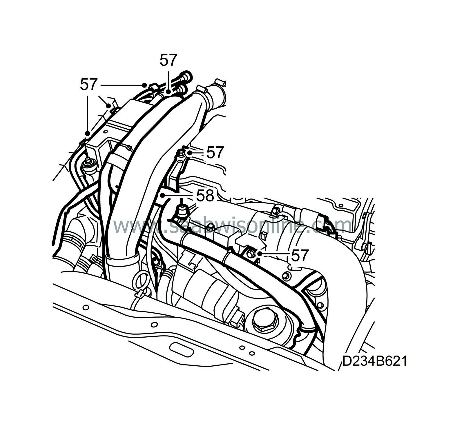
Replace and insert the wires into their holders. Replace the wiring harness channel in the cylinder head.
|
|
58.
|
Replace the turbocharger pressure pipe.
|
|
59.
|
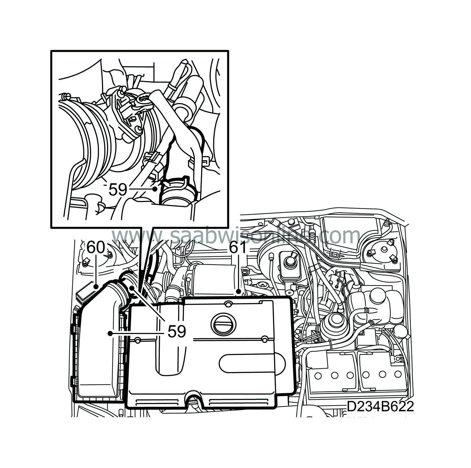
Replace the air cleaner with the mass air flow sensor and hoses.
|
|
60.
|
Replace the diesel engine's relay.
|
|
61.
|
Connect the crankcase ventilation hose to the valve cover and replace the engine cover.
|
|
62.
|
Mount the battery's negative cable and remove the wing protector.
|
|
63.
|
Set the clock and radio code if needed.
|
|
Marking the modification identity plate
|
Upon completion of the necessary procedure, box A2 on the modification identity plate must be marked. If the work was carried out by the importer, mark the box with a "7". If done by a dealer, mark it with an "8".
|
Standard times-/Warranty information
|
See separate information.


