Diesel pump with control module
|
|
Diesel pump with control module
|
 Warning
|
|
Removing the fuel pump involves work on the car's fuel system. The following points must therefore be considered in connection with the work:
|
|
|
|
|
|
|
•
|
Make provision for good ventilation! If approved ventilation for extracting fuel fumes is available then it must be used.
|
|
•
|
Use protective gloves! Prolonged contact with fuel may irritate the skin.
|
|
•
|
Keep a class BE fire extinguisher close at hand! Watch out for sparks, e.g. in connection with breaking electric circuits, short-circuits, etc.
|
|
•
|
Smoking is absolutely forbidden.
|
|
1.
|
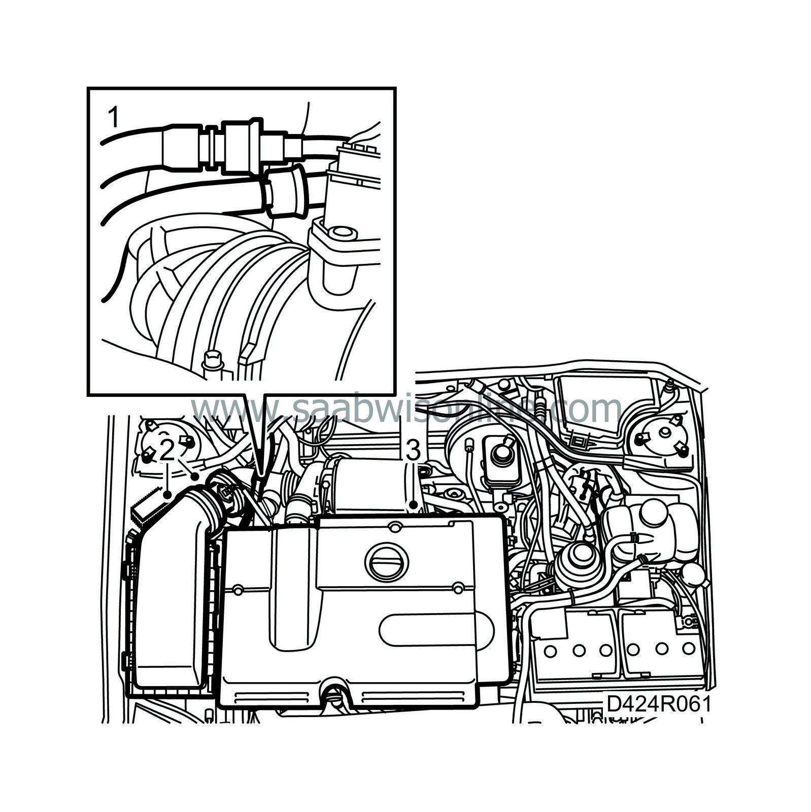
Separate the fuel hoses with tool 83 95 261 and seal them.
|
|
2.
|
Remove the air cleaner with mass air flow sensor and hoses.
|
|
3.
|
Remove the engine cover.
|
|
4.
|
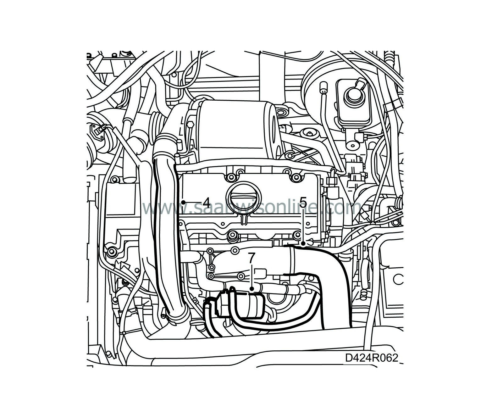
Remove the charge air pipe with connecting hose. Plug the hoses.
|
|
5.
|
Detach the air hose from the EGR valve adapter, bend it to one side and plug the hose.
|
|
6.
|
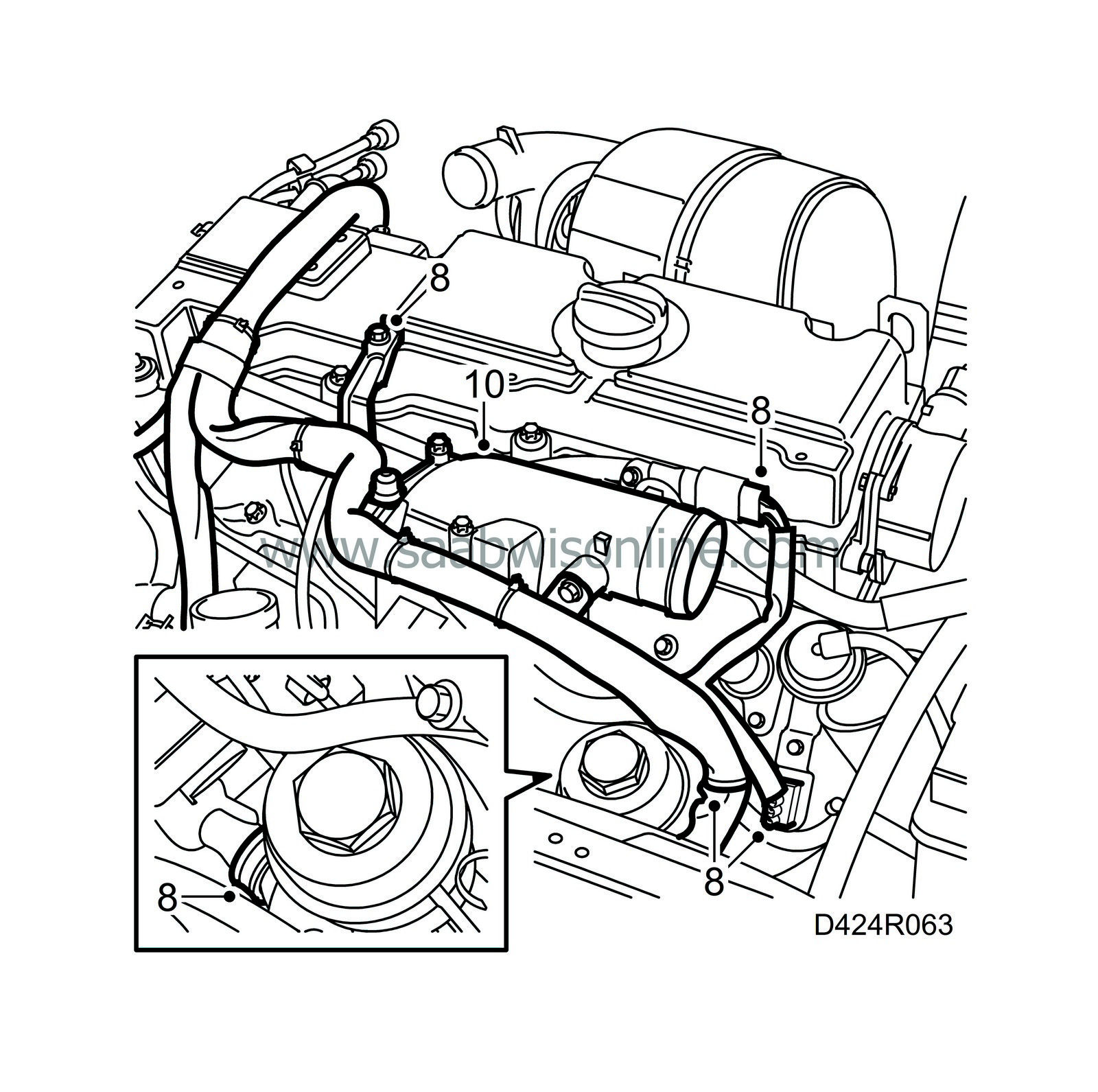
Disconnect all the cables to the engine harness duct and cut the fixations.
|
|
7.
|
Undo the EGR valve and move to one side.
|
|
8.
|
Remove the cable channel from the cylinder head and lay it over the engine.
|
|
9.
|
Unplug the control module connector.
|
|
10.
|
Remove the throttle body.
|
|
11.
|
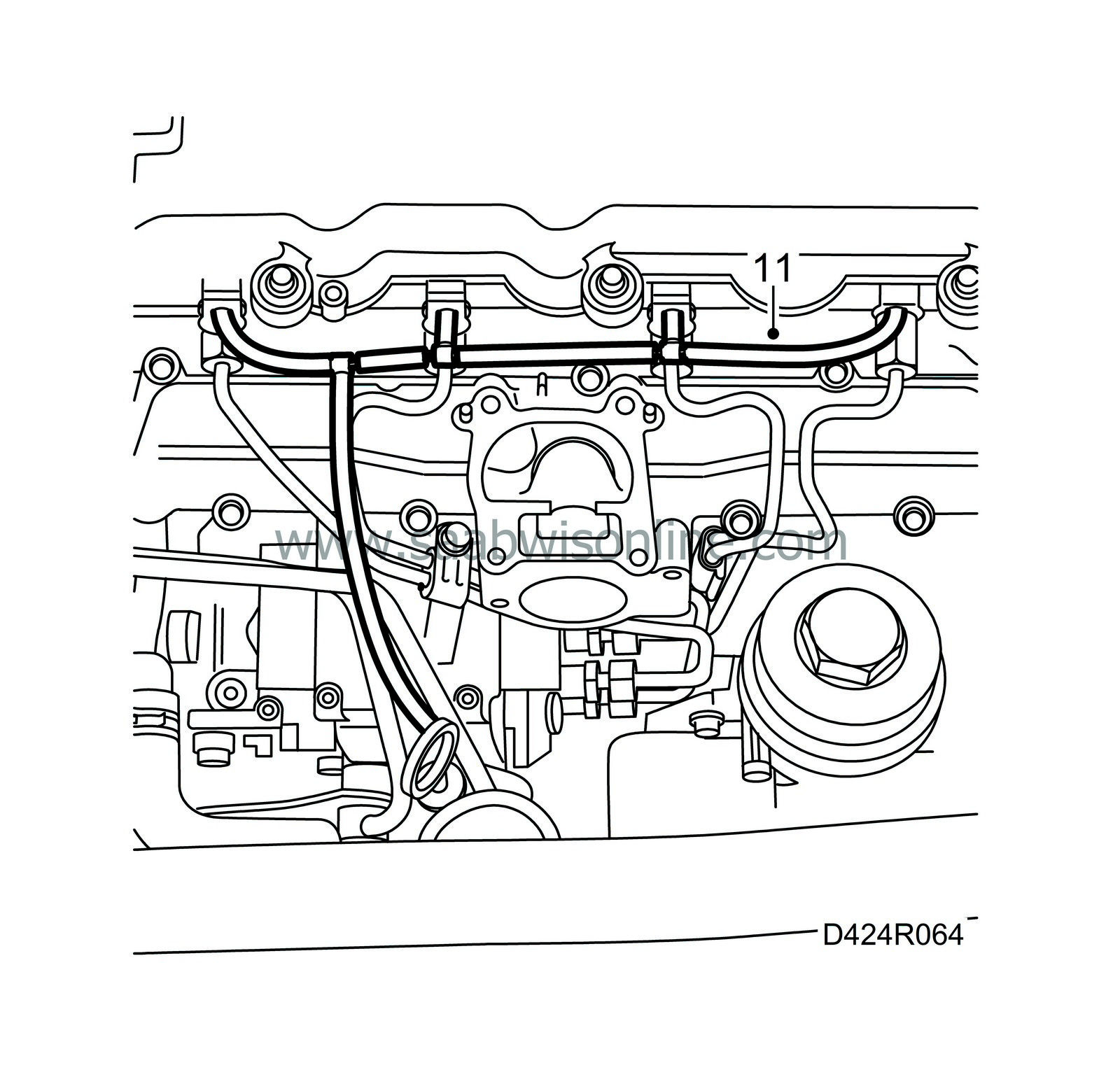
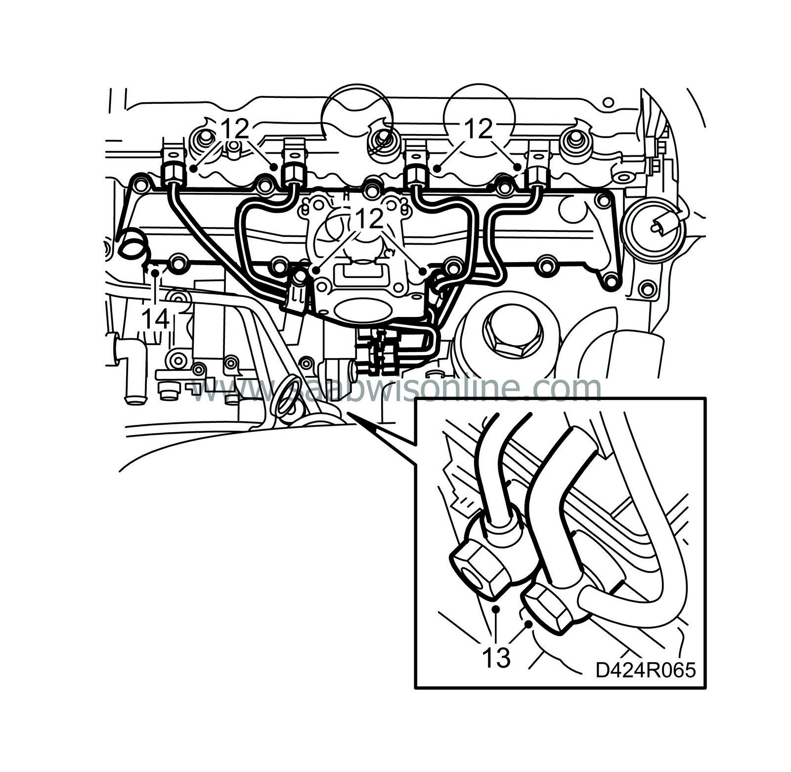
Detach the fuel return hoses from the fuel bridges.
|
|
12.
|
Mark the position of the fuel rails with clamps and remove the rails.
|
|
13.
|
Remove the fuel lines from the fuel distribution pump with control module.
|
|
14.
|
Remove the upper section of the intake manifold.
|
|
15.
|
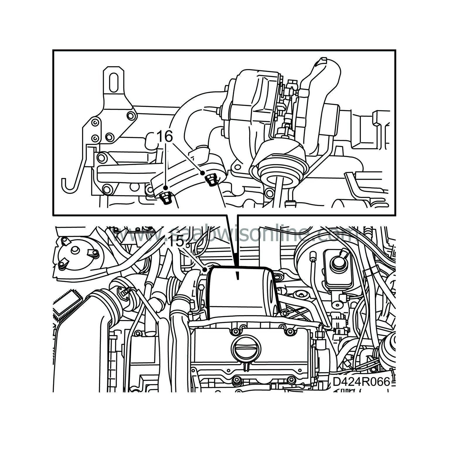
Removing the turbo unit's heat shield.
|
|
16.
|
Remove the exhaust pipe at its connection with the turbocharger.
|
|
17.
|
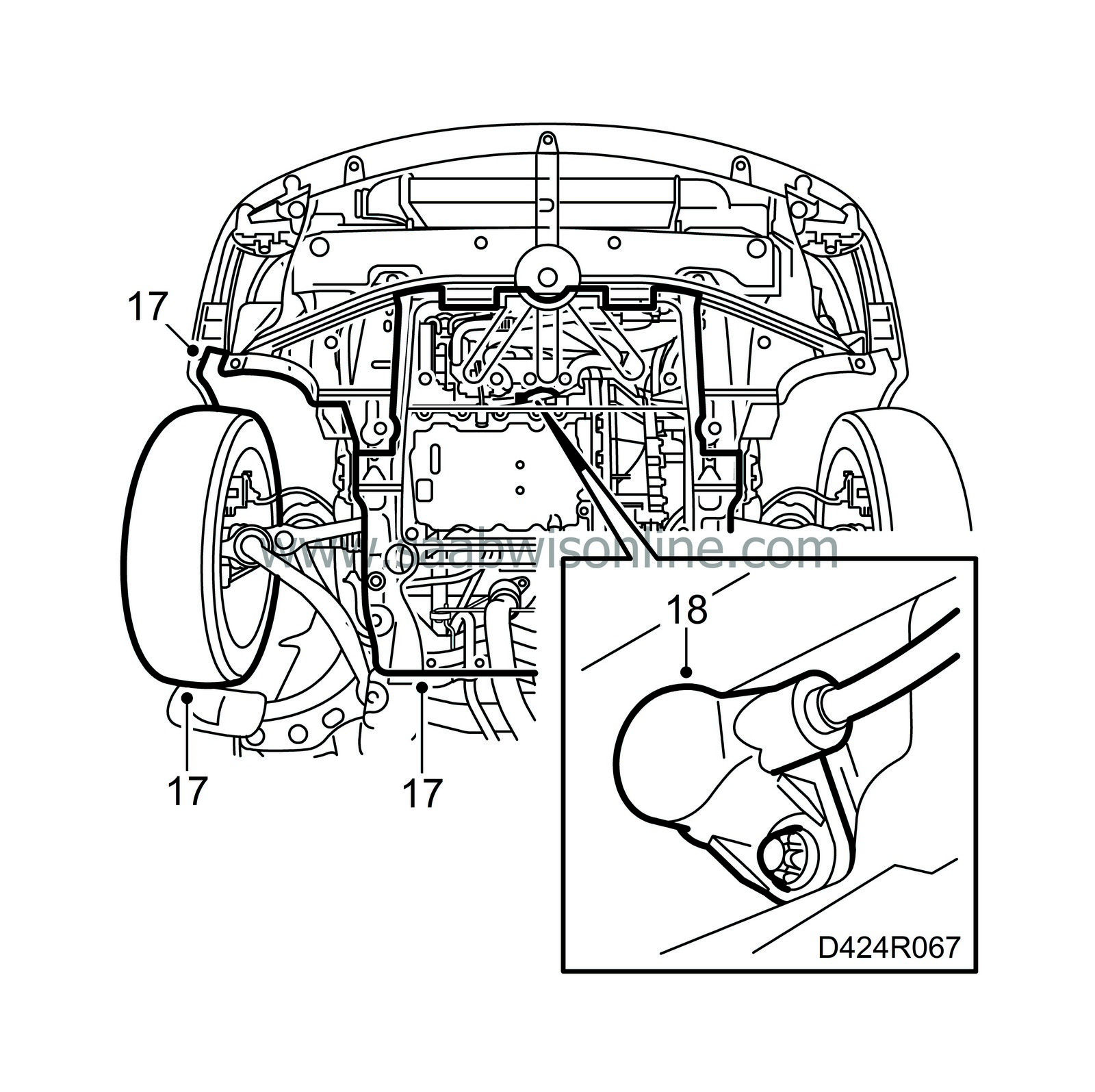
Raise the car and remove the front right wheel, lower engine cover and the belt circuit cover.
|
|
18.
|
Remove the crankshaft position sensor with O-ring.
|
|
19.
|
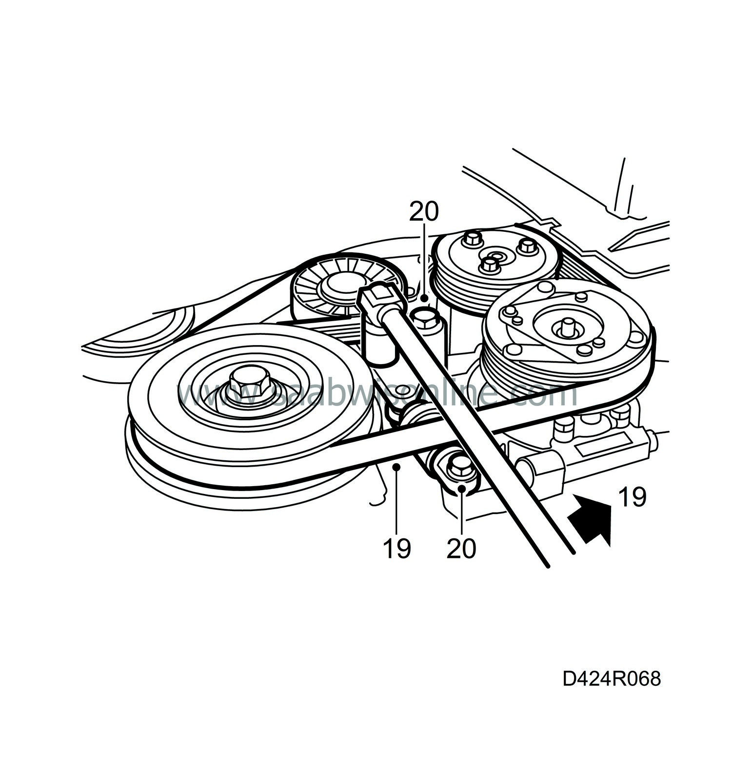
Relieve the tension on the belt tensioner by turning it anticlockwise using a 19 mm spanner. Lift off the belt.
|
|
20.
|
Remove the belt tensioner.
|
|
21.
|
Lower the car and place a jack with wood block under the oil sump.
|
|
22.
|
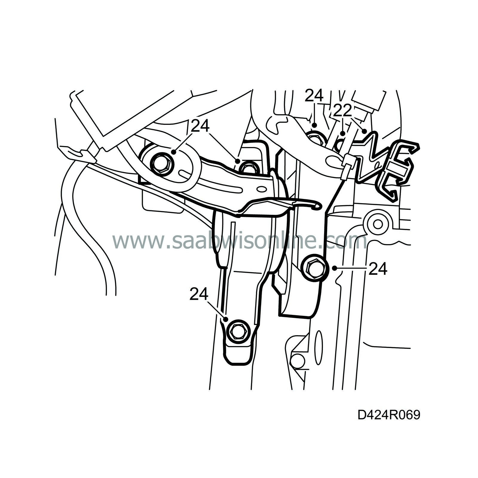
Detach the wiring harness with bracket and bend it to one side.
|
|
23.
|
Carefully lift up the engine to take the weight off the engine pads.
|
|
24.
|
Remove the right-hand engine pad from the engine and the body.
|
|
25.
|
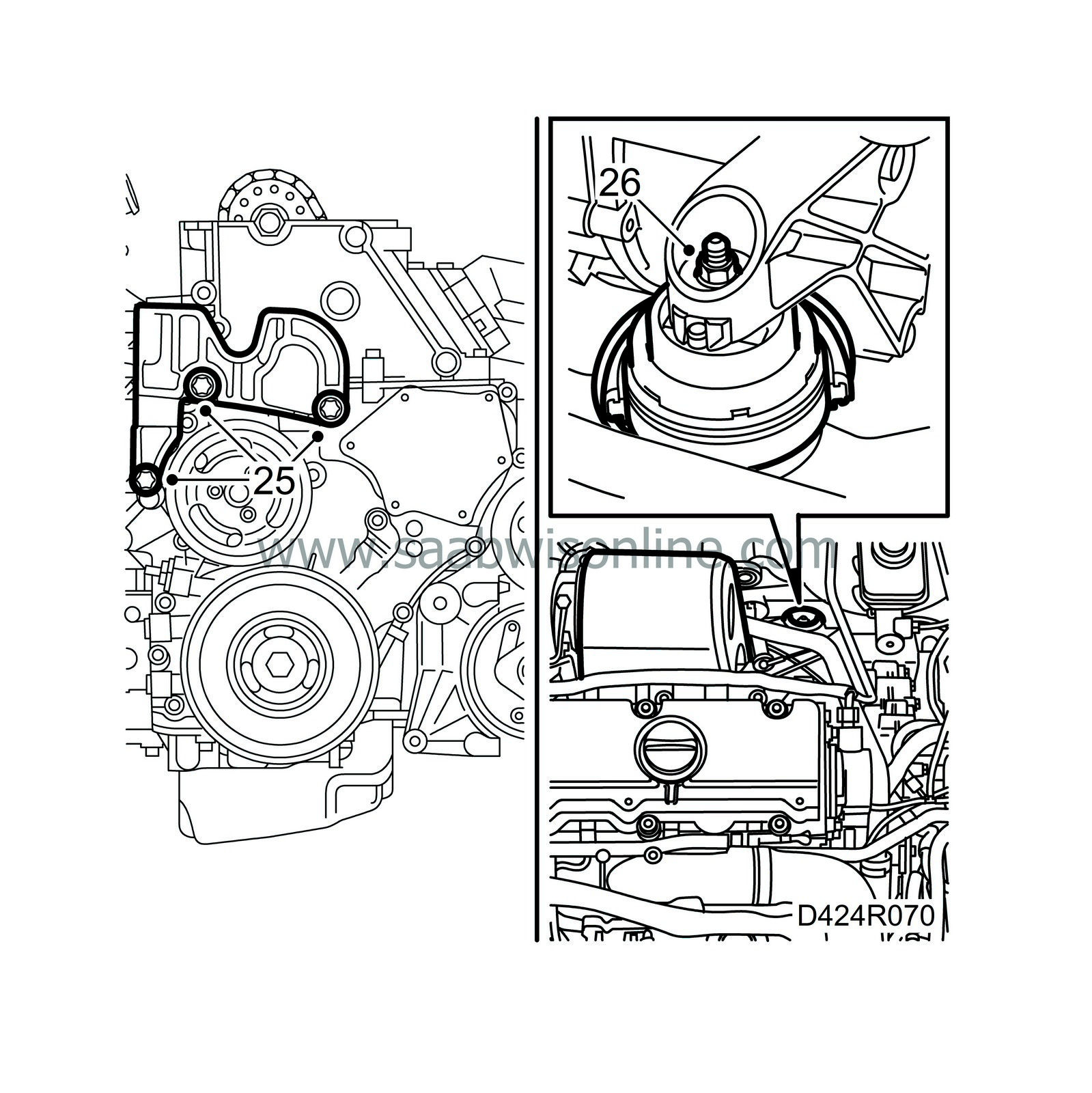
Remove the engine mounting (the lower bolt need not be removed completely).
|
|
26.
|
Remove the nut from the rear engine pad and lift the engine some more.
|
Important
|
|
Make sure nothing is damaged when the engine is moved.
|
|
|
|
|
27.
|
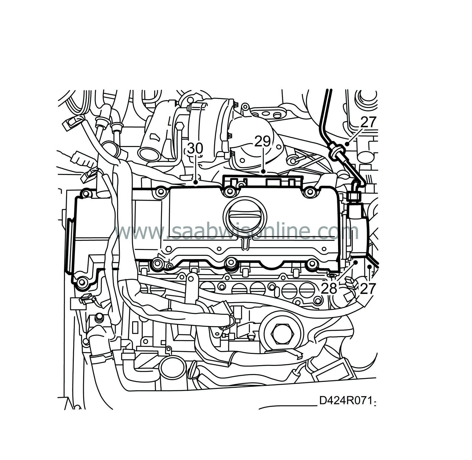
Detach the vacuum hose on the brake servo and the vacuum hose connected to the bottom of the vacuum pump.
|
|
28.
|
Remove and carefully lift away the vacuum pump with adapter.
|
Important
|
|
Note the position of the vacuum pump.
|
|
|
|
|
29.
|
Undo the clips for the wiring harness behind the camshaft cover.
|
|
30.
|
Remove the camshaft cover.
|
|
31.
|
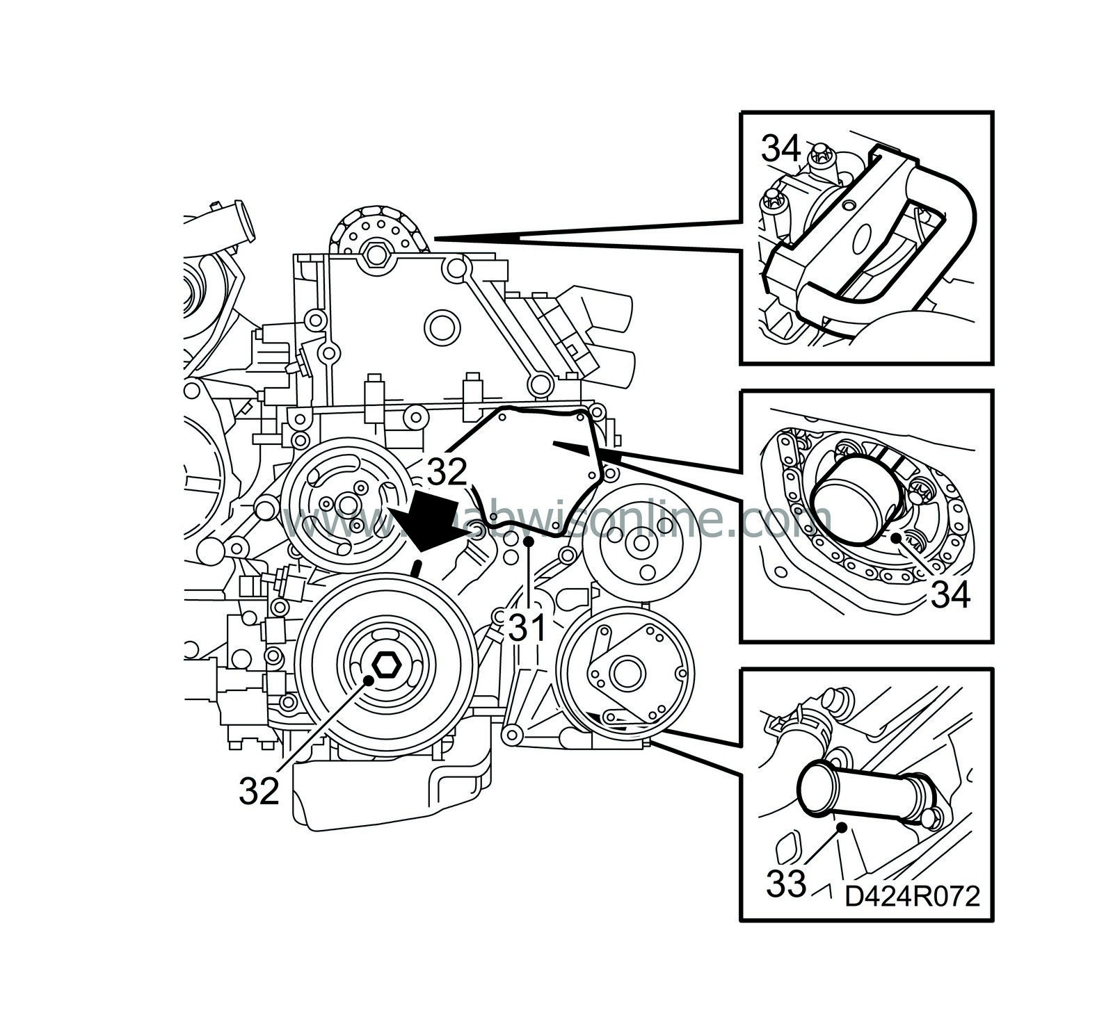
Remove the screws for the timing cover cap, carefully insert a spatula behind the cover and prise it off carefully.
|
Important
|
|
Be careful, as there is otherwise a risk of deforming the cover and causing leaks.
|
|
|
|
|
32.
|
Rotate the crankshaft two turns to just before the mark for TDC in cylinder 1. Check that both cams for cylinder 1 are pointing diagonally upwards.
|
|
33.
|
Position the inspection gauge 83 95 352 into the hole for the crankshaft position sensor. Press in the tool at the same time as the crankshaft is turned to the zero marking. The tool will then enter a recess in the crankshaft and lock it.
|
|
34.
|
Position the inspection gauge 83 95 337 into the recess in the fuel distributor pump and the inspection gauge 83 95 386 to the camshaft and cylinder head.
|
|
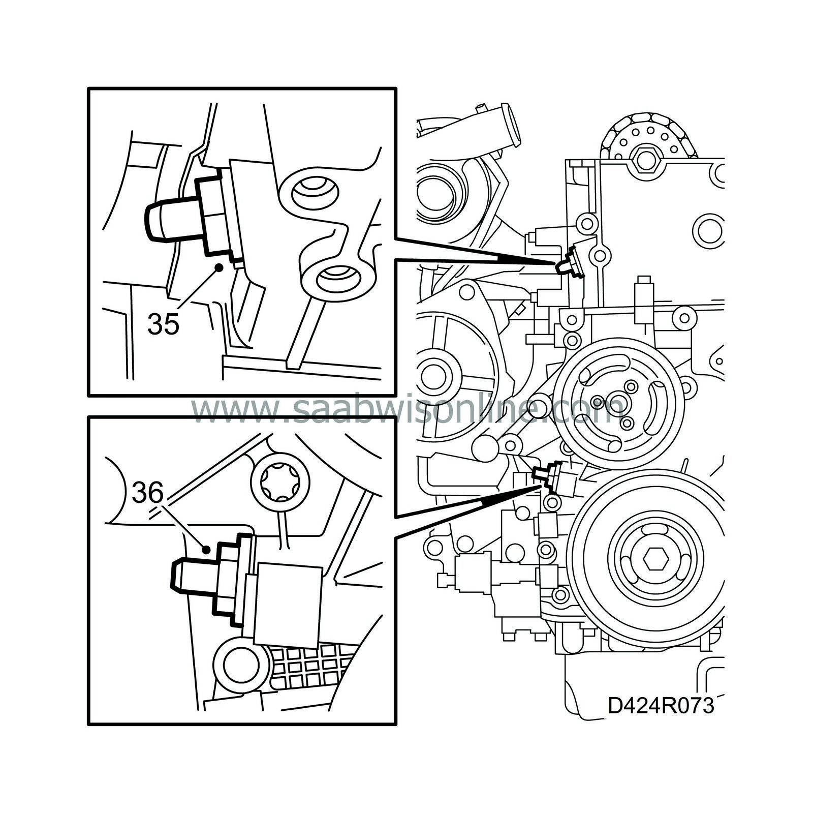
35.
|
Remove the upper timing chain tensioner.
|
|
36.
|
Remove the lower timing chain tensioner.
|
|
37.
|
Remove inspection gauge 83 95 337 from the fuel pump recess.
|
|
38.
|
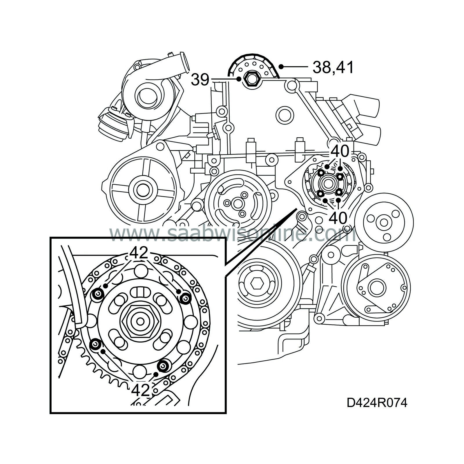
Secure the upper timing chain to the camshaft sprocket with a cable tie.
|
|
39.
|
Remove the camshaft gear using an open-end spanner as a backstop in the hexagonal recess on the camshaft.
|
|
40.
|
Undo the bolts on the fuel distributor pump chain drive and remove the pinion. Use sleeve 83 95 543.
|
Important
|
|
Remove only the four bolts,
not
the centre nut.
|
|
|
|
|
41.
|
Pull up the chain and remove it.
|
|
42.
|
Remove the four retaining bolts on the fuel distributor pump that are accessible through the hole in the timing chain cover.
|
|
43.
|
Place a receptacle under the car. Connect a hose to the engine block drain nipple. Drain the coolant.
|
|
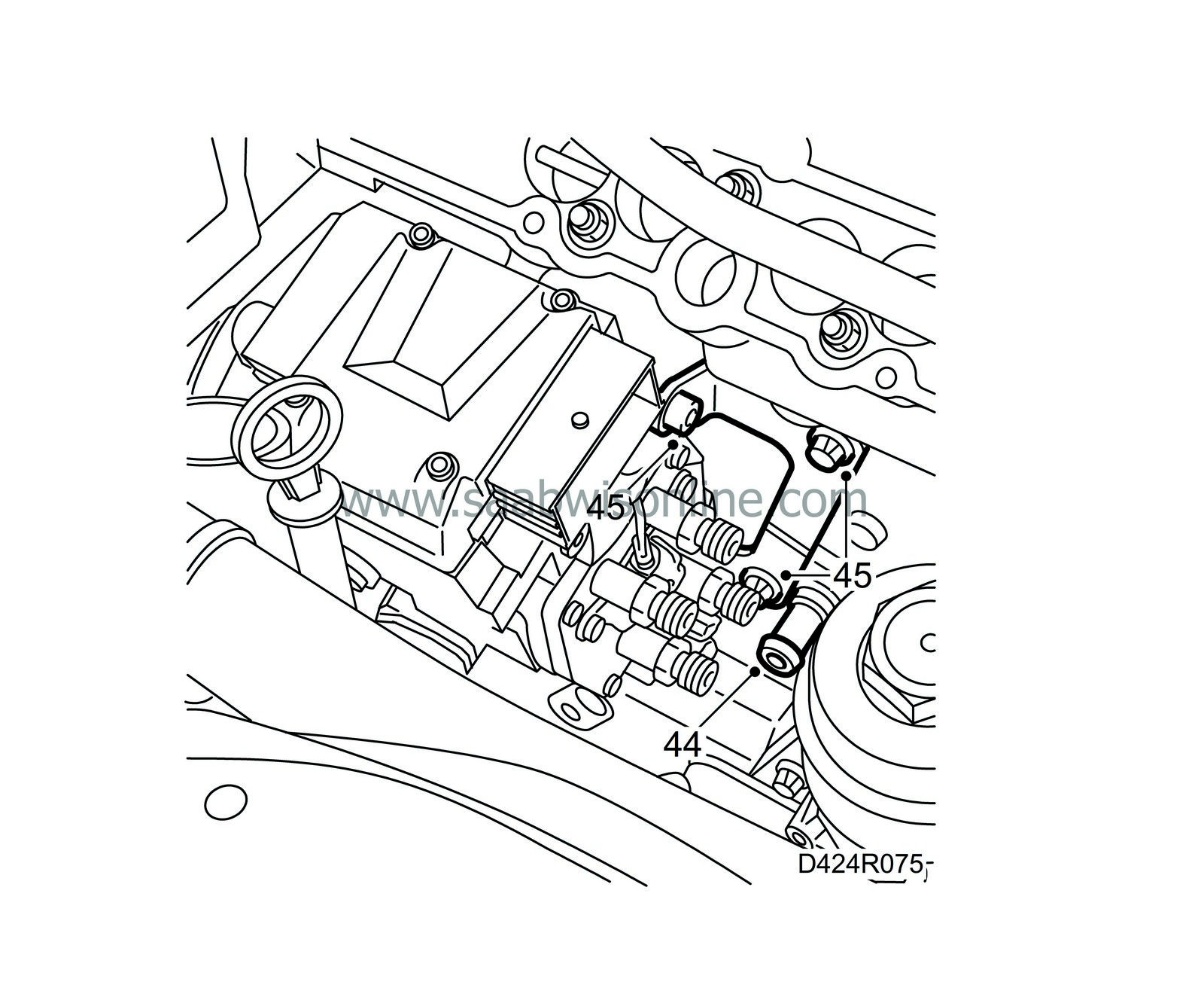
44.
|
Remove the drain nipple.
|
Important
|
|
ESD-SENSITIVE COMPONENT
|
|
Ground yourself by touching the car body or engine before unplugging or plugging in the component.
Never touch the connector pins.
Prior to changing a control module refer to
Before changing a control module
.
|
|
|
|
|
45.
|
Remove the bracket from the fuel distributor pump and the cylinder block, and remove the fuel pump.
|
|
1.
|
Clean the sealing surfaces.
|
|
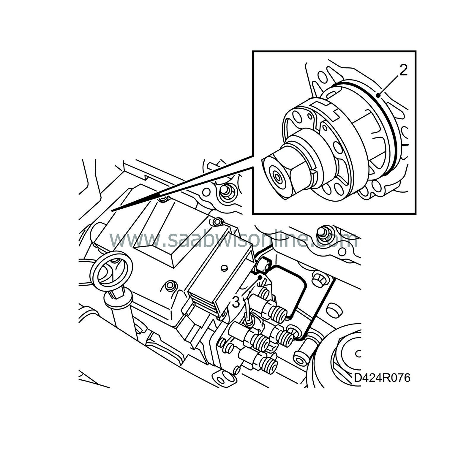
2.
|
Fit a new O-ring onto the fuel distribution pump, lubricate the O-ring with acid-free petroleum jelly and position the pump to the cylinder block.
|
|
3.
|
Transfer the bracket to the pump if the pump has been changed.
Tightening torque 20 Nm (15 lbf ft).
Insert the bolts for the bracket into the cylinder block without tightening them.
|
|
4.
|
Position the inspection gauge 83 95 337 into the recess in the fuel distributor pump.
|
|
5.
|
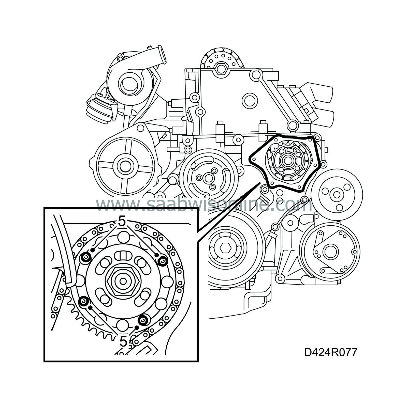
Tighten the bolts through the opening in the timing cover. Use sleeve 83 95 543.
Tightening torque 25 Nm (19 lbf ft).
|
|
6.
|
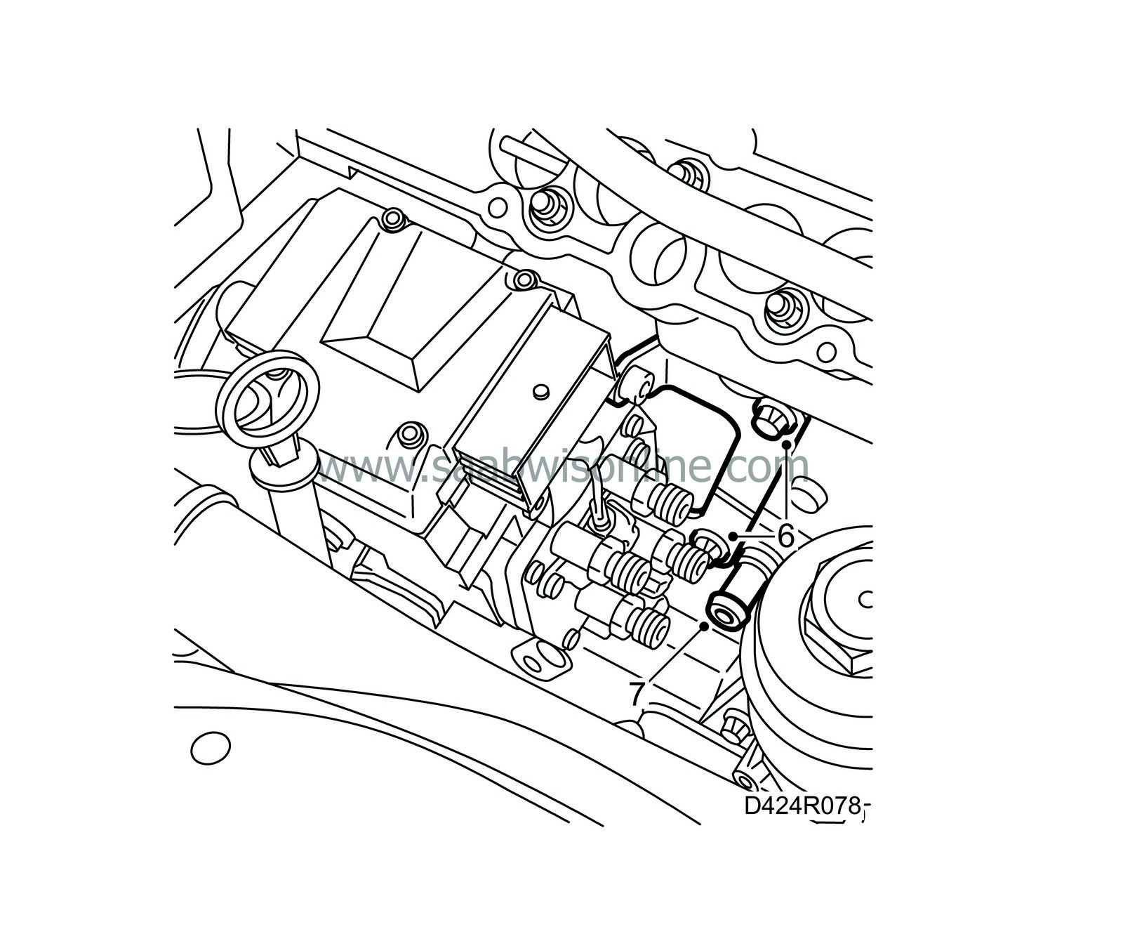
Tighten the screws securing the bracket to the cylinder block.
Tightening torque 20 Nm (15 lbf ft).
|
|
7.
|
Fit the engine block drain plug with a new O-ring.
|
|
8.
|
Remove the inspection gauge from the fuel distributor pump.
|
|
9.
|
Release the upper timing chain, position the sprocket on the fuel distributor pump, fit the sprocket with one bolt, fit the chain and tighten the bolts on the sprocket by hand.
|
Important
|
|
The arrow on the sprocket must be aligned with the recess on the flange and the hole in the pump.
|
|
|
|
|
10.
|
Position the inspection gauge 83 95 337 into the recess in the fuel distributor pump again.
|
|
11.
|
Position the camshaft gear on the camshaft.
|
|
12.
|
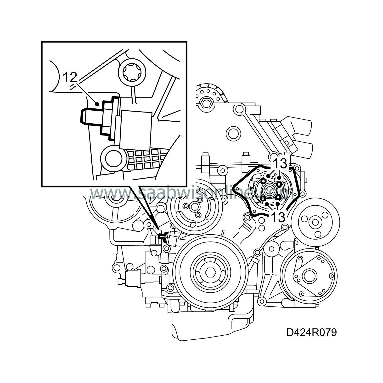
Fit the chain tensioner for the lower timing chain with a new gasket.
Tightening torque 60 Nm (44 lbf ft).
|
|
13.
|
Remove the inspection gauge from the fuel distributor pump and tighten the bolts on the sprocket.
Tightening torque 20 Nm (15 lbf ft).
|
|
14.
|
Position the inspection gauge 83 95 337 into the recess in the fuel distributor pump again.
|
|
15.
|
Make sure the camshaft gear runs freely on the camshaft and fit a new bolt. Tighten it by hand.
|
|
16.
|
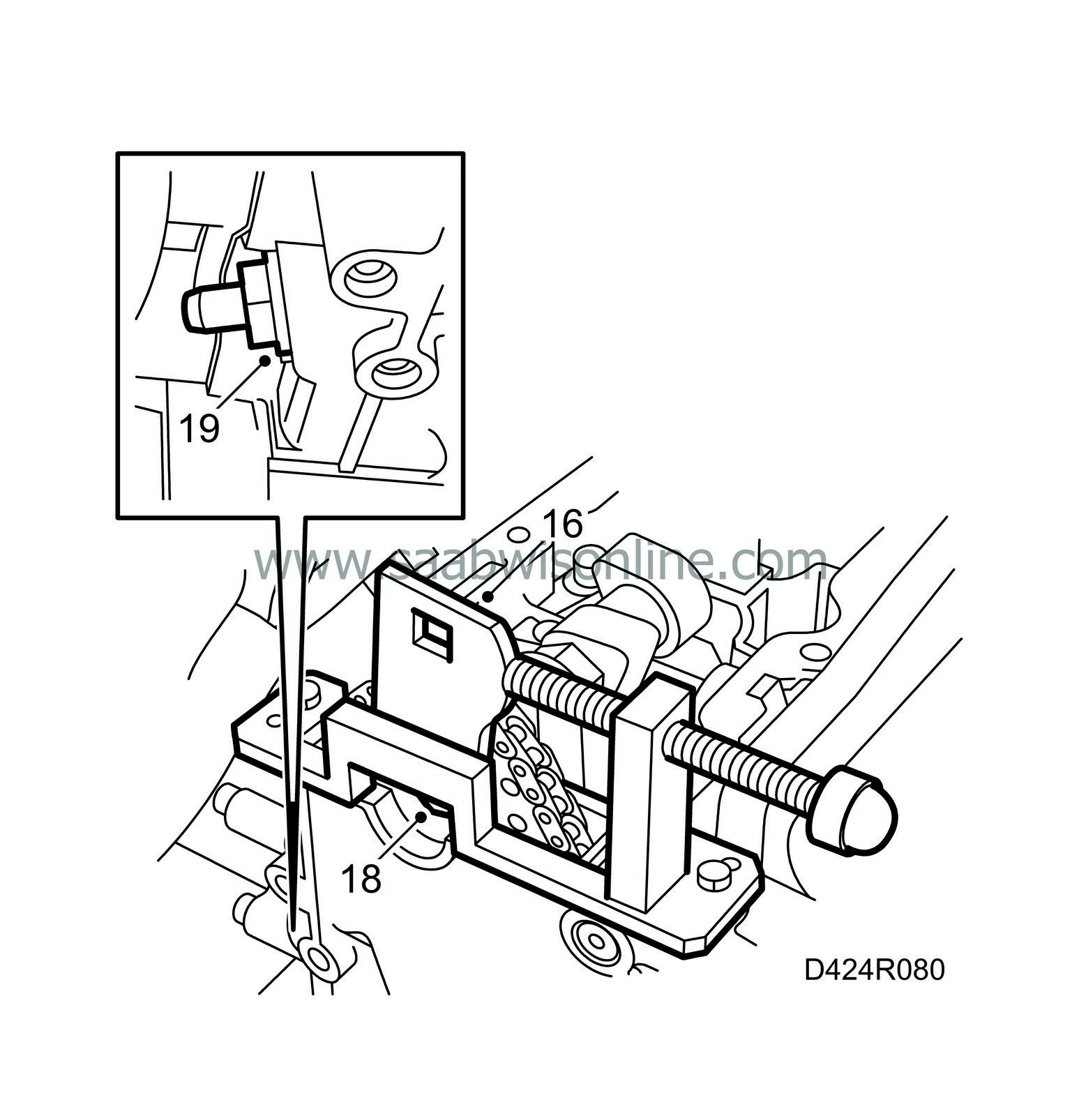
Fit the adapter for timing chain adjuster 83 95 394 onto the camshaft gear and fit the adjuster on the cylinder head.
|
|
17.
|
Secure the position of the adapter on the camshaft gear by turning it slightly anti-clockwise with a ratchet handle. Tighten the adjuster screw on the tool.
|
Important
|
|
Inspection gauge 83 95 337 must be easily removed and fitted the whole time. If this is not the case then slightly loosen the adjuster screw on the tool.
|
|
|
|
|
18.
|
Tighten the bolt on the camshaft gear.
Tightening torque 90 Nm (67 lbf ft) + 60°.
|
|
19.
|
Fit the chain tensioner for the upper timing chain with a new gasket.
Tightening torque 60 Nm (44 lbf ft).
|
|
20.
|
Remove all the tools and gauges.
|
|
21.
|
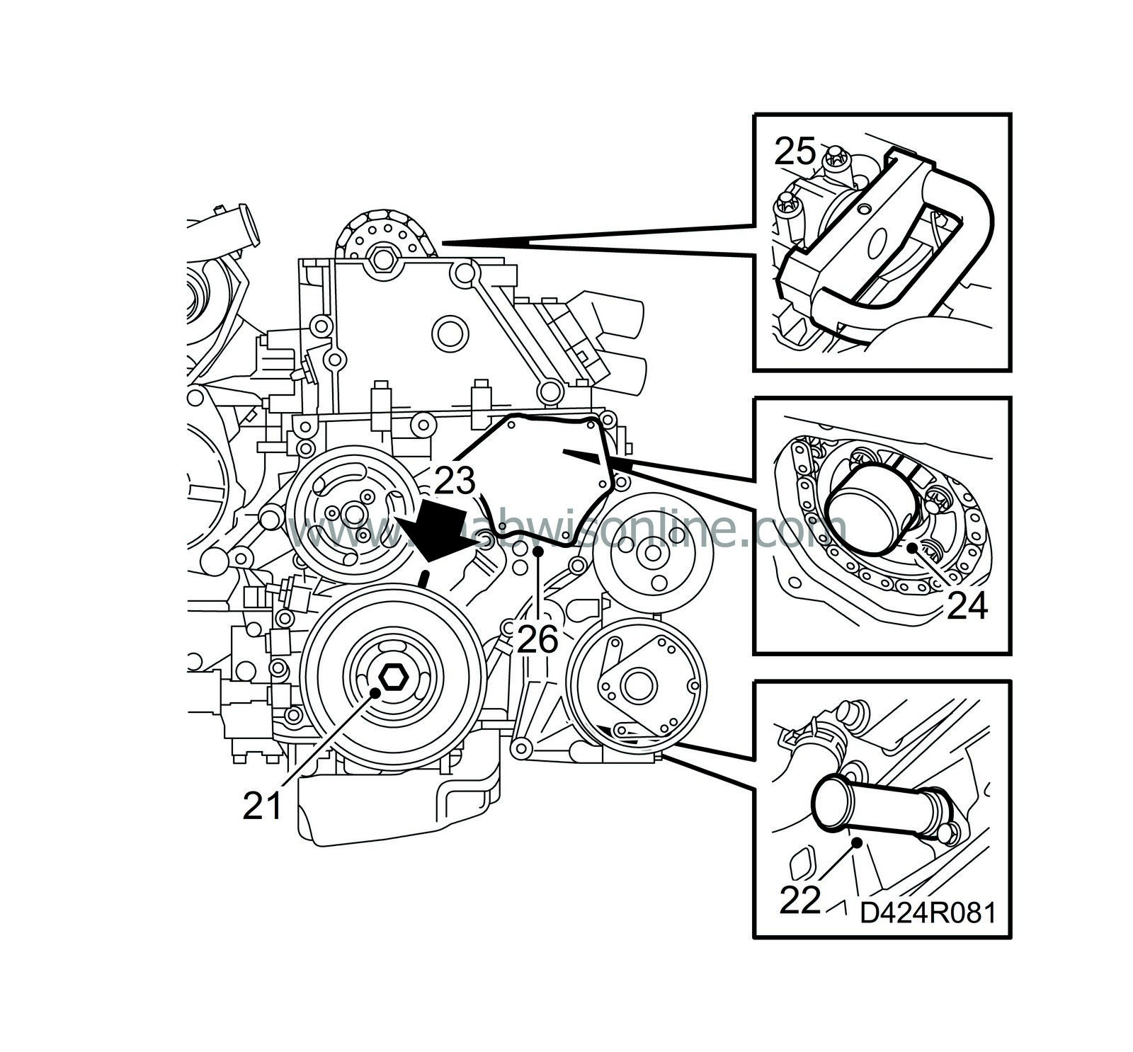
Rotate the crankshaft two turns to just before the mark for TDC in cylinder 1. Check that both cams for cylinder 1 are pointing diagonally upwards.
|
|
22.
|
Position the inspection gauge 83 95 352 into the hole for the crankshaft position sensor. Press in the tool at the same time as the crankshaft is turned to the zero marking. The tool will then enter a recess in the crankshaft and lock it.
|
|
23.
|
Make sure the markings on the crankshaft pulley and the timing cover are aligned. The arrow on the single timing chain sprocket on the fuel distributor pump must also be aligned with the recess in the pump.
|
|
24.
|
Position the inspection gauge 83 95 337 into the recess in the fuel distributor pump.
|
|
25.
|
Position the inspection gauge 83 95 386 to the camshaft and cylinder head.
|
|
26.
|
Remove all the inspection gauges.
|
|
27.
|
Cover the opening in the timing cover with a lint-free cloth and clean the sealing surfaces from any remains of the old gasket. Also, clean the sealing surface on the cap.
|
|
28.
|
Lay a string of flange sealant 87 81 841 about 2 mm thick on the cap, remove the cloth from the timing cover and fit the cap.
Tightening torque 6 Nm (5 lbf ft).
|
|
29.
|
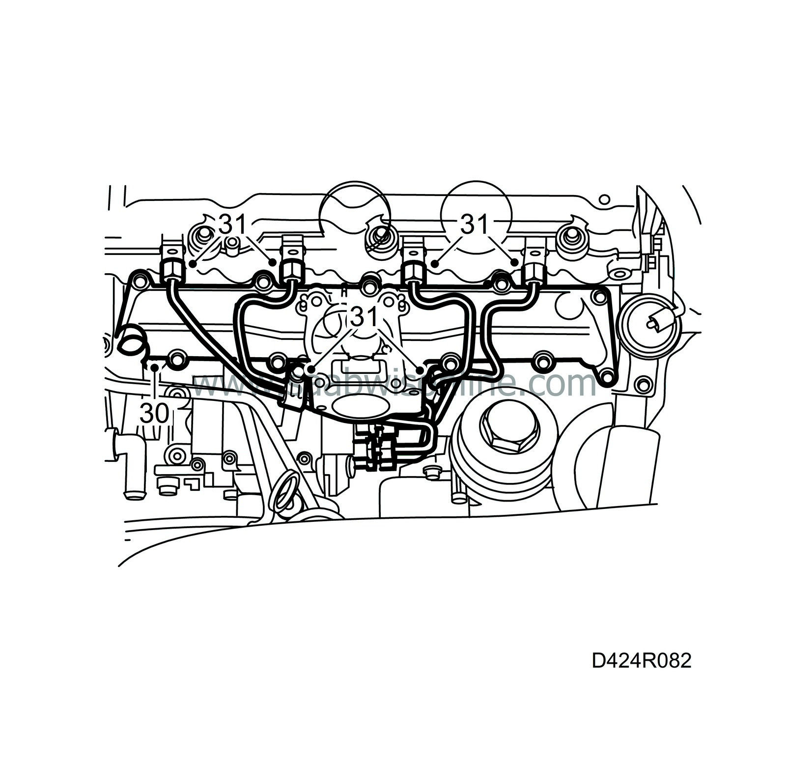
Clean the sealing surfaces on the upper part of the intake manifold.
|
|
30.
|
Fit a new gasket onto the lower part of the intake manifold and fit the upper part.
Tightening torque 10 Nm (7 lbf ft).
|
|
31.
|
Fit the fuel rails.
Tightening torque 25 Nm (18 lbf ft).
|
|
32.
|
Plug in the pump control module rear connector.
|
|
33.
|
Clean the sealing surfaces on the cylinder head from remains of the old gasket.
|
|
34.
|
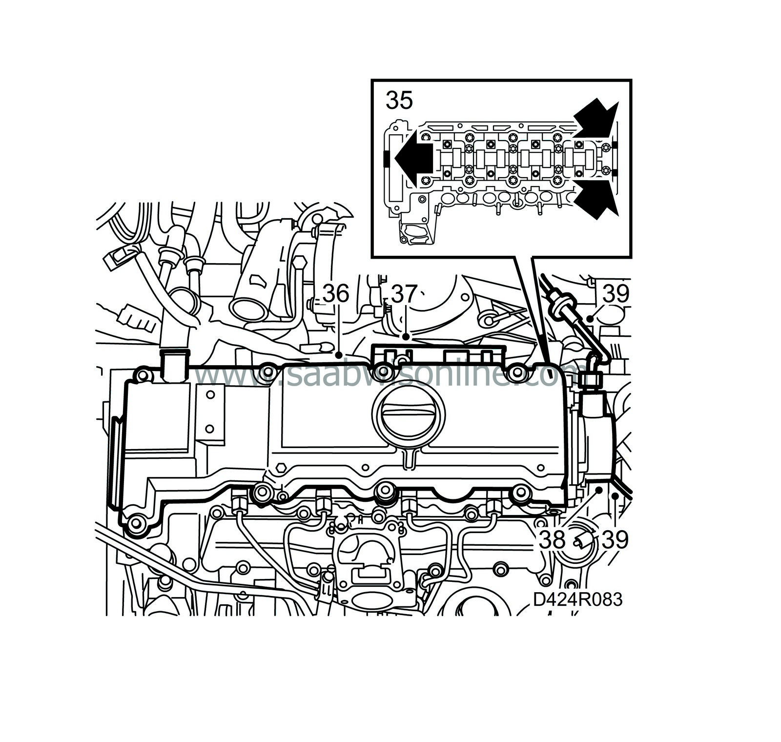
Position a new gasket on the camshaft cover. The bolts have sleeves on which the gasket fits.
|
|
35.
|
Apply sealing compound 87 81 841 to the sealing surface, see illustration.
|
|
36.
|
Position the camshaft cover on the cylinder head and tighten the bolts.
Tightening torque 8 Nm (6 lbf ft).
|
|
37.
|
Fit the wiring harness clips behind the camshaft cover.
|
|
38.
|
Fit a new seal on the vacuum pump and fit the pump together with the adapter.
|
Important
|
|
The vacuum pump must be fitted in the same position as previously.
|
|
|
Tightening torque 8 Nm (6 lbf ft).
|
|
39.
|
Connect the vacuum hose for the brake servo to the vacuum pump.
Tightening torque 18 Nm (13 lbf ft).
Connect the vacuum hose to the bottom of the vacuum pump.
|
|
40.
|
Plug in the pump control module front connector
|
|
41.
|
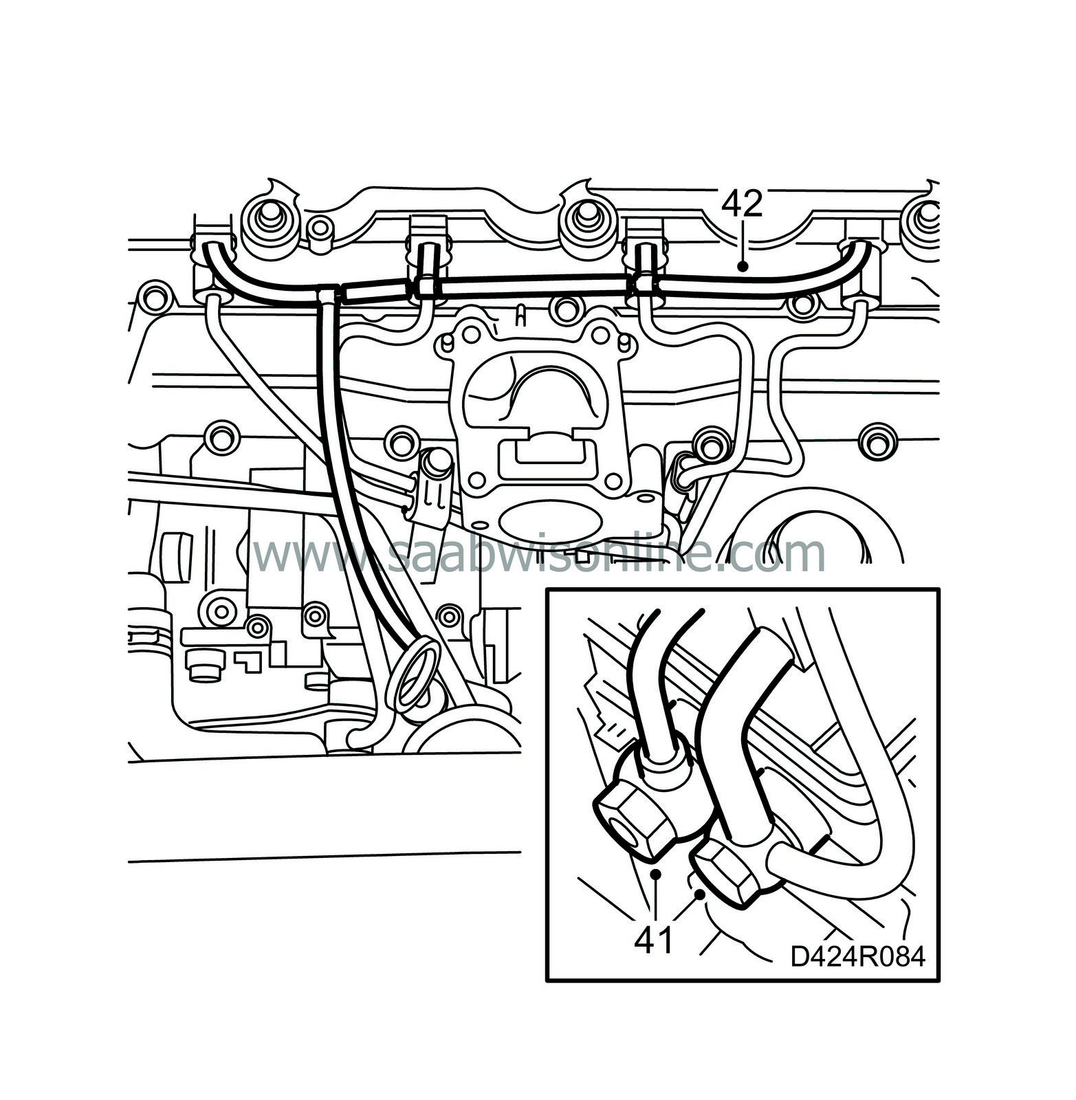
Fit the fuel lines to the fuel pump with new seals.
Tightening torque 25 Nm (19 lbf ft)
Connect the fuel line quick-release couplings.
|
|
42.
|
Fit new fuel return hoses.
|
|
43.
|
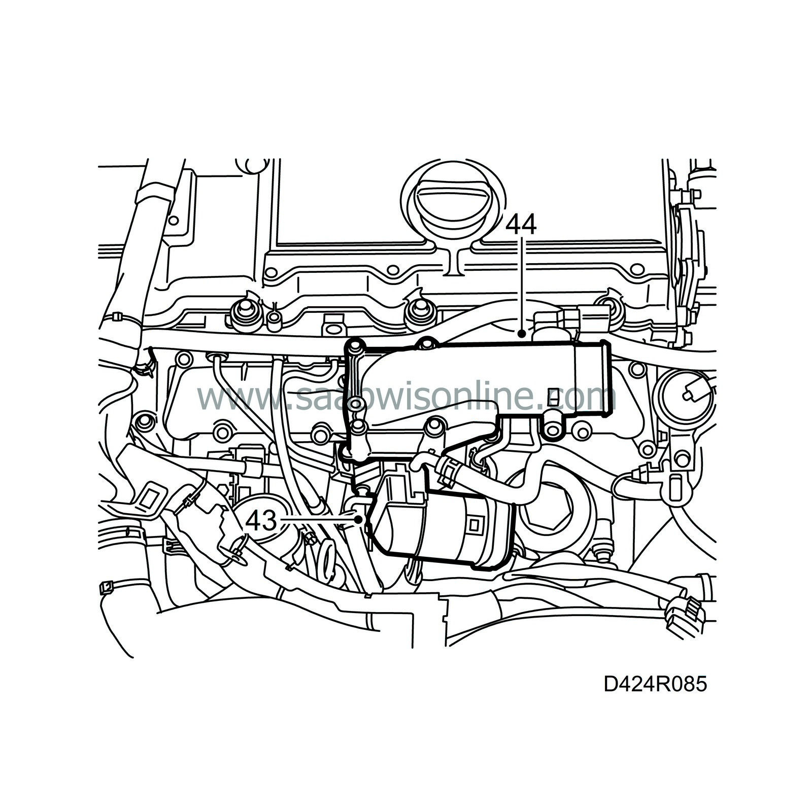
Fit the EGR valve with a new O-ring
Tightening torque 10 Nm (7 lbf ft)
|
|
44.
|
Fit the throttle body with a new gasket.
Tightening torque 10 Nm (7 lbf ft)
|
|
45.
|
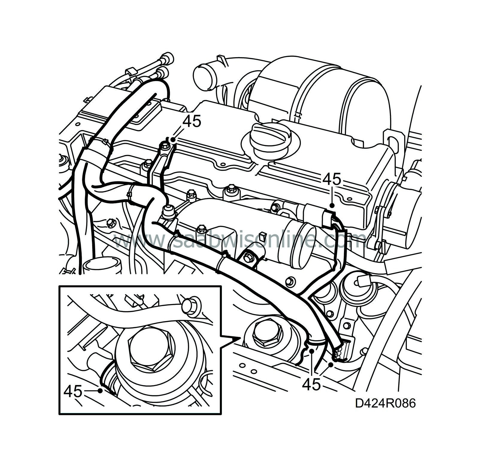
Fit the wiring harness channel to the cylinder head and attach the cables.
|
|
46.
|
Secure the wiring harness as it was previously.
|
|
47.
|
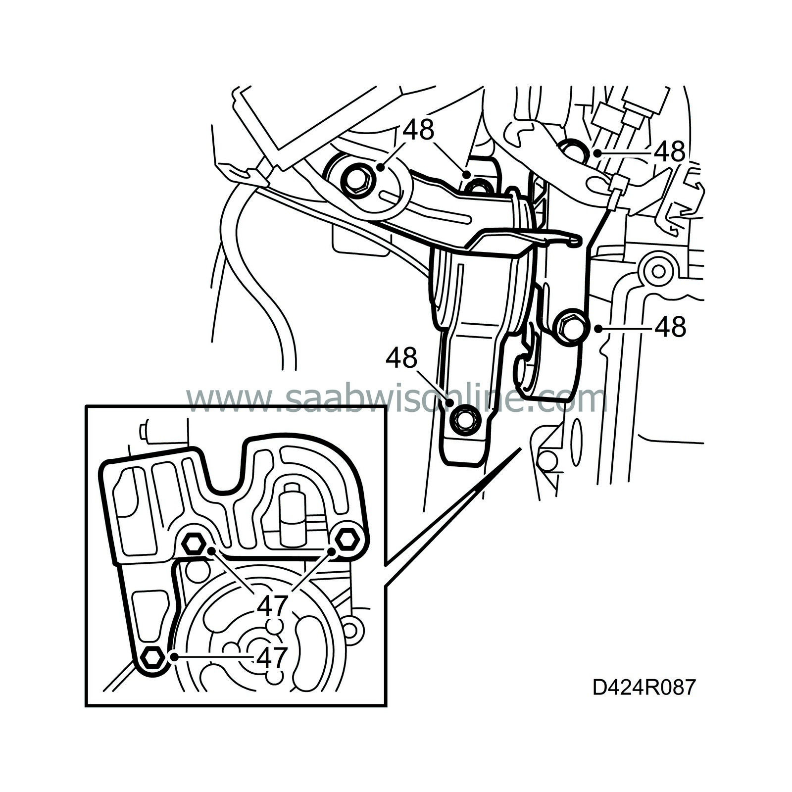
Fit the right-hand engine pad bracket onto the timing cover.
Tightening torque 47 Nm (35 lbf ft).
|
|
48.
|
Position the right-hand engine pad, lower the engine and tighten the right-hand engine pad bolts.
Tightening torque 47 Nm (35 lbf ft).
|
|
49.
|
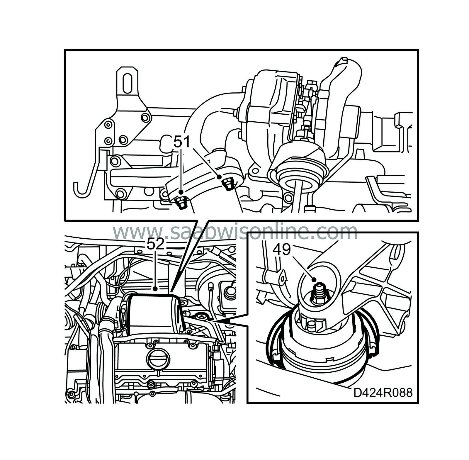
Tighten the nut on the rear engine pad.
Tightening torque 47 Nm (35 lbf ft).
|
|
50.
|
Raise the car, apply Molycote 1000 to the studs on the turbocharger, position the front part of the exhaust pipe together with a new gasket and fit new nuts.
|
|
51.
|
Tighten the front exhaust pipe on the turbocharger.
Tightening torque 20 Nm (15 lbf ft).
|
|
52.
|
Fit the turbocharger heat shield.
|
|
53.
|
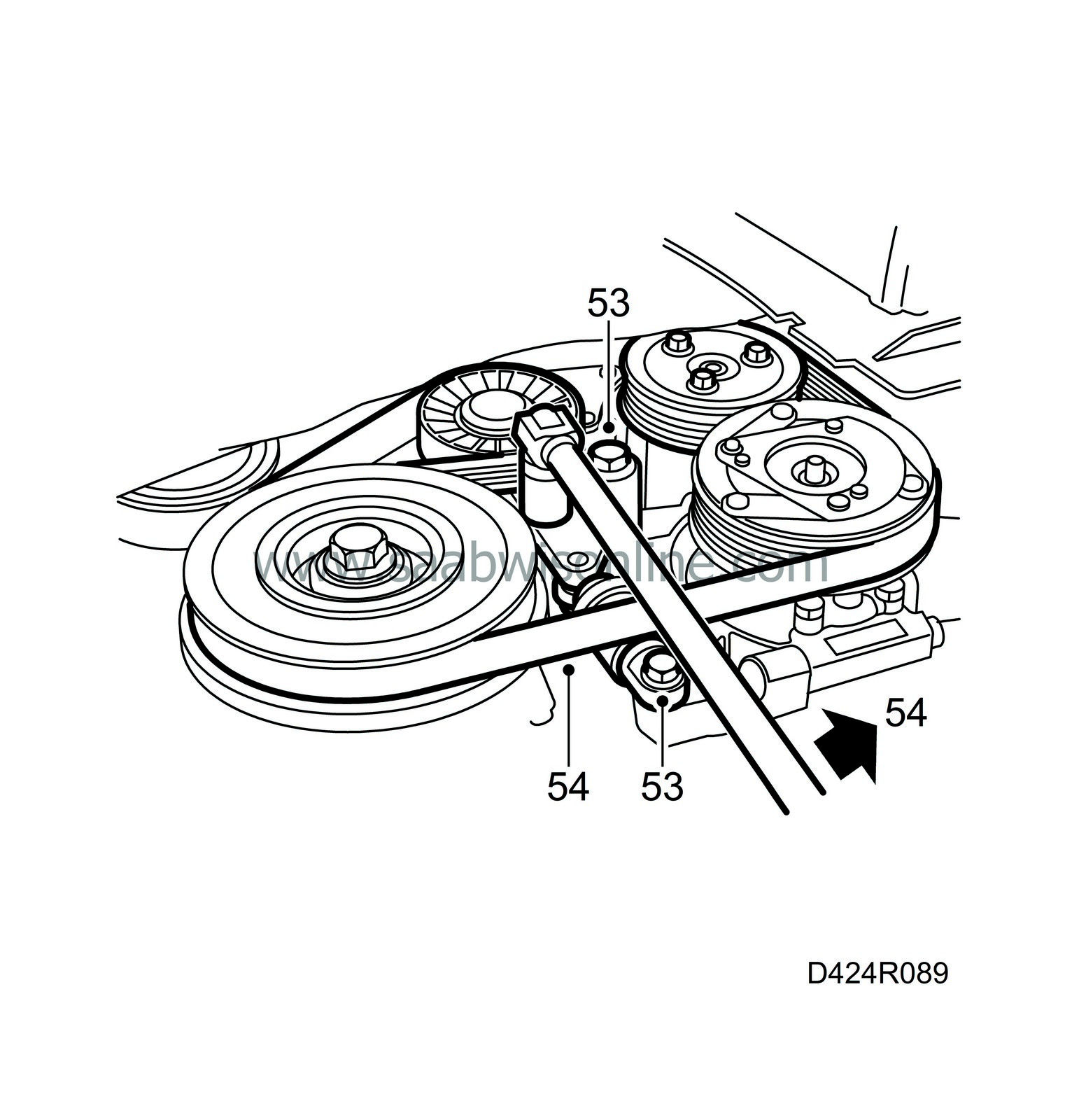
Fit the belt tensioner and tighten the top bolt first.
Tightening torque 42 Nm (31 lbf ft).
Tighten the bottom bolt.
Tightening torque 23 Nm (17 lbf ft).
|
|
54.
|
Fit the multigroove V-belt on all the pulleys. Relieve the tension on the belt tensioner by turning it anti-clockwise (towards the rear of the car) with a 19 mm spanner and fit the belt onto the belt tensioner pulley. Check the position of the belt on all the pulleys.
|
|
55.
|
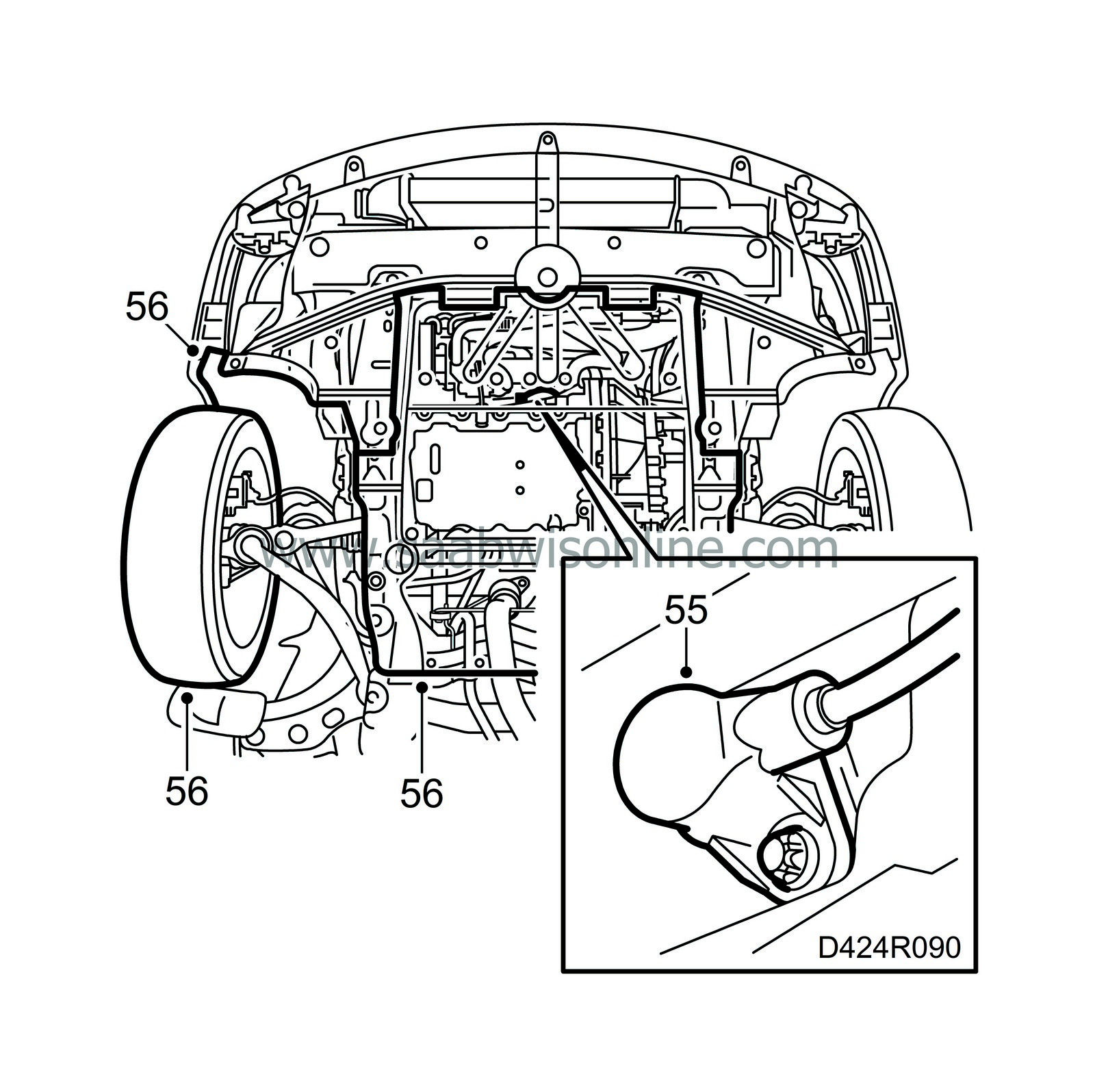
Raise the car and fit the crankshaft position sensor with a new O-ring.
Tightening torque 8 Nm (6 lbf ft).
|
|
56.
|
Fit the belt circuit cover in the right wheel housing, the lower engine cover and the wheel.
Tightening torque, wheel 110 Nm (81 lbf ft).
Lower the car.
|
|
57.
|
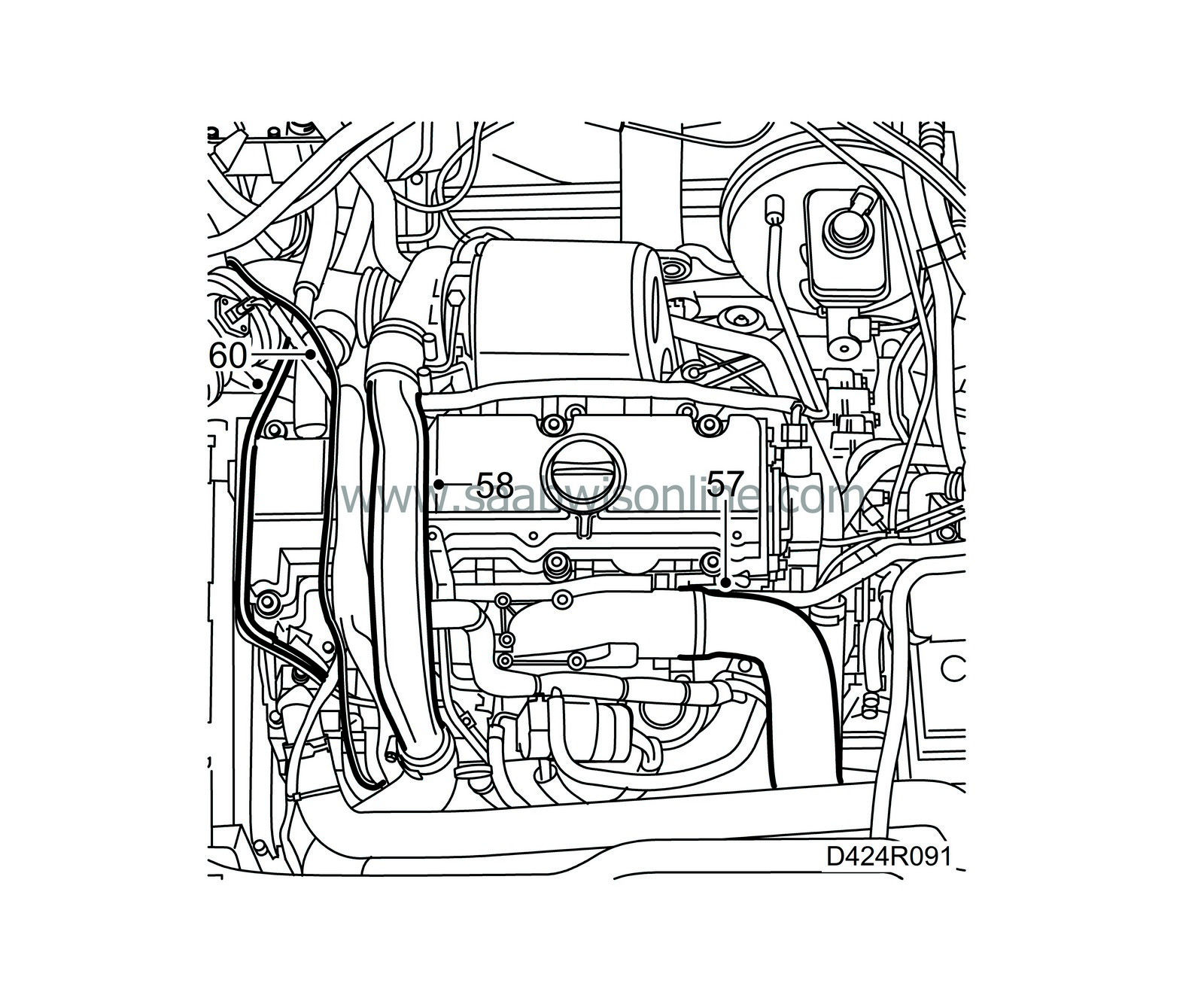
Fit the hose to the intake manifold.
|
|
58.
|
Fit the charge air pipe.
|
|
59.
|
Fill with coolant and bleed the system as follows:
|
Note
|
|
AC/ACC must be turned off.
|
|
|
60.
|
Fit the wiring harness with bracket and press the fuel lines into the attachment. Secure the wiring harness to the charge air pipe with a cable tie.
|
|
|
•
|
Connect the exhaust hose to the engine exhaust system.
|
|
|
•
|
Check that there is a continuous flow of coolant in the hose from the thermostat housing to the expansion tank. Rev up the engine briefly to ensure circulation of the coolant.
|
|
|
•
|
Run the engine until the thermostat opens.
|
|
|
•
|
Shut off the engine and top up the cooling system if needed.
|
|
61.
|
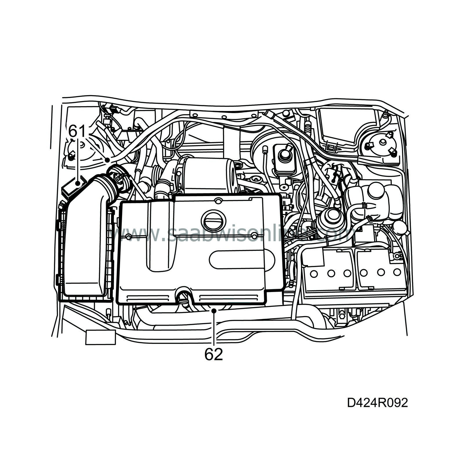
Fit the air cleaner with mass air flow sensor and hoses. Connect the hose for the crankcase ventilation.
|
|
62.
|
Fit the engine cover.
|


 Warning


