Manifold absolute pressure sensor
|
|
Manifold absolute pressure sensor
|
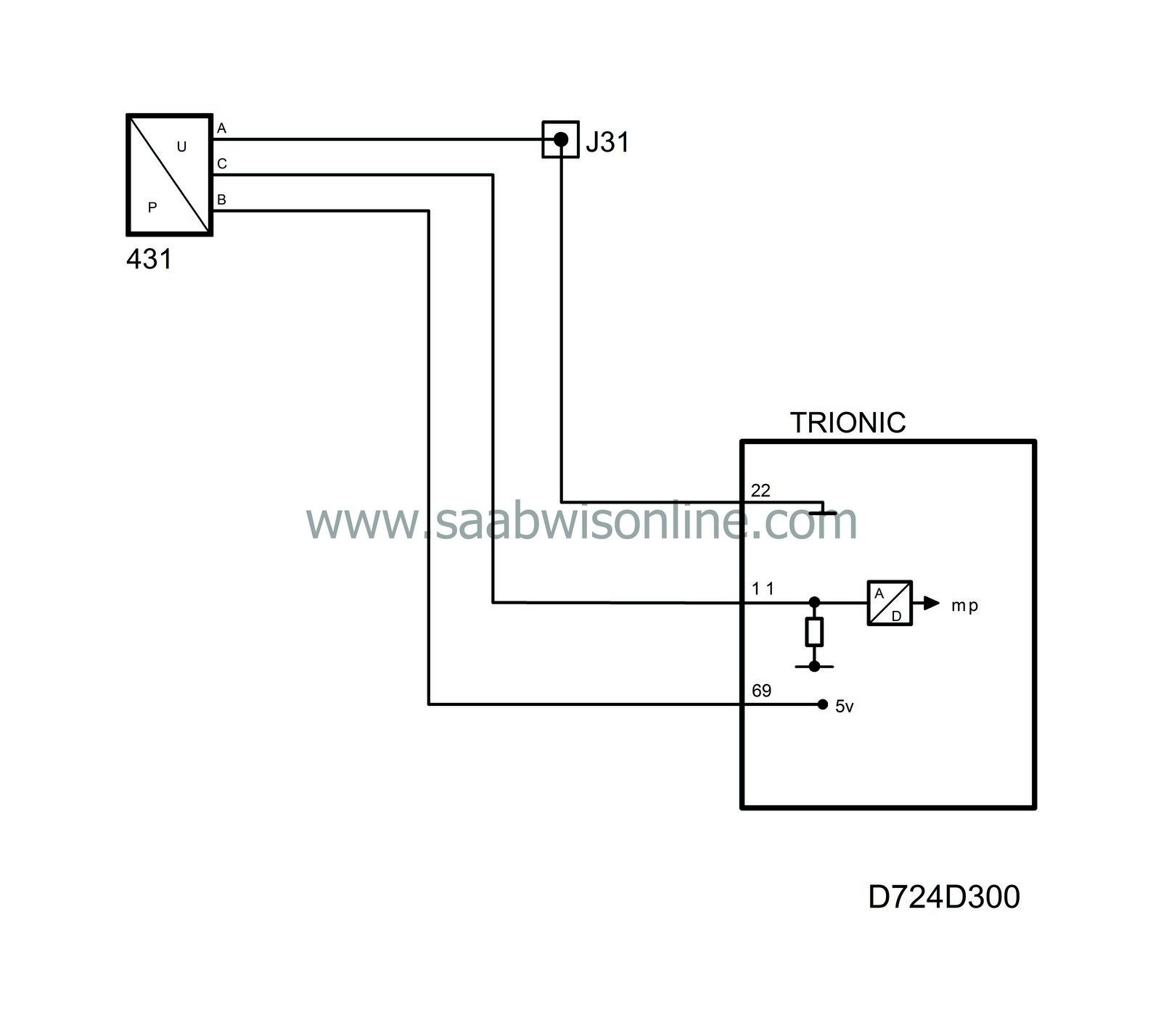
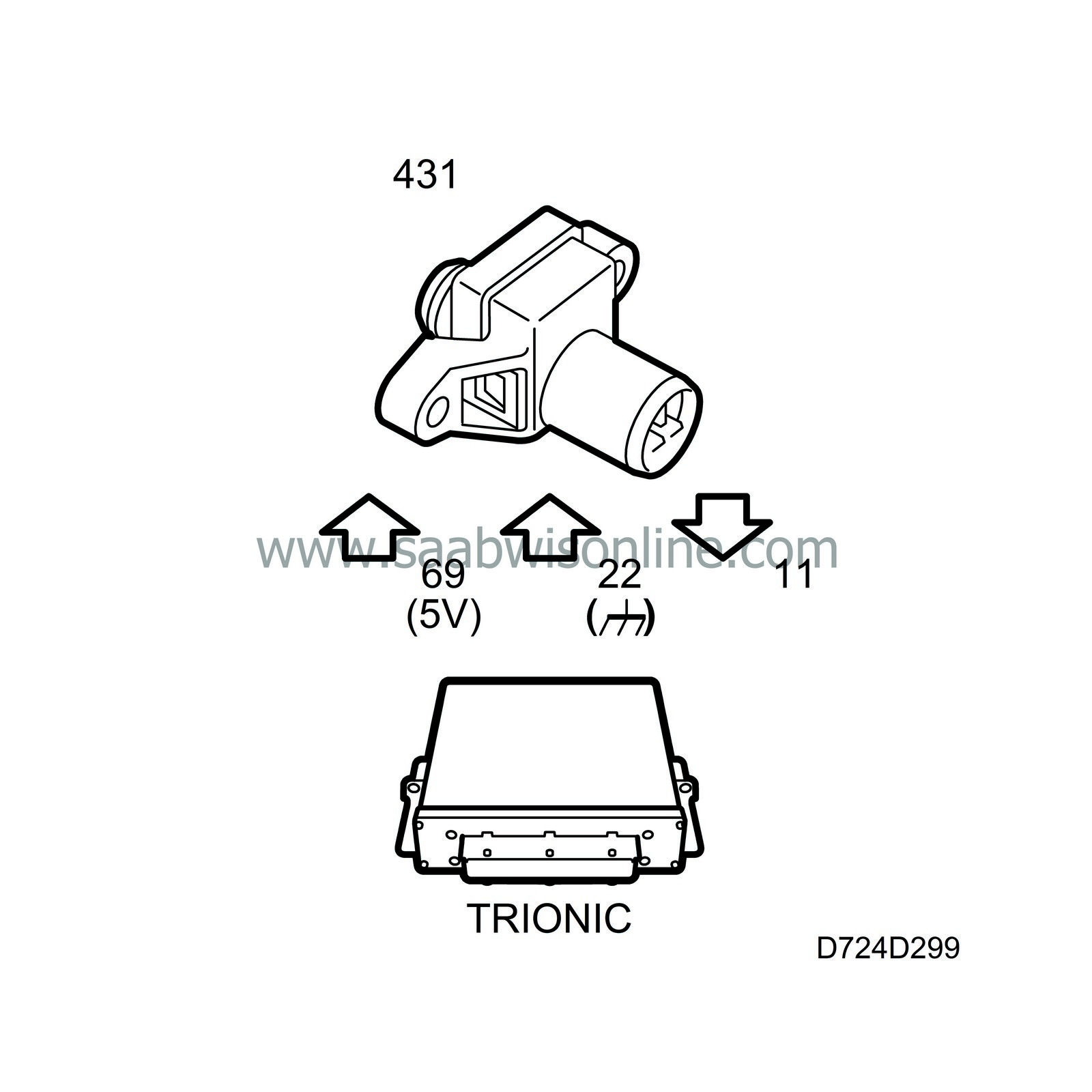
 Inside the pressure sensor there are two metal-plated ceramic discs mounted close together. The disc situated closest to the pressure connection is thinner and bends when exposed to pressure. This changes the capacitance between the metal-plated discs depending on the pressure. Integrated in the sensor is a circuit that converts capacitance to analogue voltage. The pressure sensor is screwed to the intake manifold on the engine after the throttle and is powered with 5V from control module pin 69 and grounded from control module pin 22.
Depending on the pressure in the intake manifold, the pressure sensor delivers a voltage to control module pin 11.
During rapid load changes, the engine load or calculated air mass/combustion based on the mass air flow sensor value can differ from the actual air mass being taken into the cylinder during the induction stroke. This is due to the inertia of the large volume of air present in the intake system. The intake pressure is therefore used during load changes to correct the air mass/combustion used in the basic calculation of the fuel quantity.
The pressure is also used to correct the purge PWM ratio. A greater PWM ratio is required at high intake pressures to obtain the same purge flow.
At normal atmospheric pressure, 100 kPa, the pressure from the sensor is approx. 2.1 V.
|
•
|
If the sensor voltage is too low, diagnostic trouble code P0107 will be generated.
|
|
•
|
If the sensor voltage is too high, diagnostic trouble code P0108 will be generated.
|
|
•
|
If the pressure value is implausible, diagnostic trouble code P0106 will be generated.
|
System reaction to a fault
|
•
|
Correction of air mass/combustion for fuel calculation is blocked.
|


