Brief description of the main instrument unit
|
|
Brief description of the main instrument unit
|
The main instrument unit conveys information to the driver and functions as an information link between the P bus and the I bus.
The main instrument unit has its own diagnostics function and sets a diagnostic trouble code when a fault occurs.
The main instrument unit incorporates the following:
|
•
|
Coolant temperature gauge
|
|
•
|
Instrument and display lighting
|
|
•
|
Warning and indicator lamps
|
The main instrument unit receives information from its own sensors and also from other systems. The control module processes the information, which is used to control instruments and lamps. Certain information is put on the bus.
The car is fitted with an electronic speedometer, which displays the current speed. The rear left wheel sensor sends information on the speed to the ABS control module, which processes the information and sends it on to the main instrument unit.
The main instrument unit control module stores the driven distance and displays it on the odometer display. The display contains a six-digit register, which the control module continuously updates from 000000 to 999999 km (or miles). The tripmeter contains a four-digit register, which starts at 000.0 and runs to 999.9 km (or miles).
The electronic tachometer shows the current engine speed. It receives continuous bus information concerning the engine speed from the diesel engine control unit. The display of engine speeds below 1100 rpm is damped to provide a stable reading.
The fuel gauge gives the driver information on how much fuel is left in the tank. It consists of a fuel gauge in the main instrument unit and a level sensor in the tank.
If the remaining fuel is below 10 litres, the main instrument unit control module will switch to measuring the fuel consumption. Information arrives on the bus from the diesel engine control module. This provides a more accurate display of the fuel level. The fuel reserve lamp comes on when the amount of fuel is below 10 litres.
|
Coolant temperature gauge
|
The coolant temperature gauge provides the driver with information on the engine coolant temperature. This information arrives on the bus from the diesel engine control module.
|
Warning and indicator lamps
|
The main instrument unit contains the following lamps:
|
•
|
Indicator lamp INFO DISPL, lights up when a message is shown on the SID unit.
|
|
•
|
Central warning lamp, lights up when a fault occurs in a system having to do with the car's safety.
|
|
•
|
Oil pressure warning lamp, warns the driver when engine oil pressure is too low.
|
|
•
|
Charge warning lamp, indicates to the driver whether or not the generator is charging.
|
|
•
|
AIRBAG warning lamp, warns the driver when a fault has occurred in the airbag system.
|
|
•
|
Brake fluid level warning lamp, warns the driver if the level in the brake fluid reservoir is too low or if there is a fault in the ABS system.
|
|
•
|
Handbrake warning lamp, indicates to the driver that the handbrake is on.
|
|
•
|
ABS warning lamp, the lamp lights up when there is a fault in the ABS system.
|
|
•
|
Fuel reserve indicator lamp, the lamp lights up when the fuel level is below 10 litres.
|
|
•
|
CHECK ENGINE indicator lamp, warns the driver that there is a fault in the engine management system.
|
|
•
|
Direction indicator repeater lamps, right and left. Show when the direction indicators are on.
|
|
•
|
CRUISE indicator lamp, on cars with cruise control the lamp lights up when cruise control is engaged.
|
|
•
|
Lights-on indicator lamp, indicates that the headlamps are on.
|
|
•
|
Rear fog light indicator lamp, indicates that the rear fog light is on.
|
|
•
|
Main beam indicator lamp, indicates that the main beam is on.
|
|
•
|
Glow indicator lamp. Lights up during pre-heating.
|
|
•
|
Door indication, indicates if any of the doors or the luggage compartment is open.
|
|
Instrument and display lighting
|
The main instrument unit's control module controls the instrument and display lighting according to the light intensity in the compartment in combination with the selected rheostat setting. This gives a good level of lighting for day or night driving and optimum bulb life.

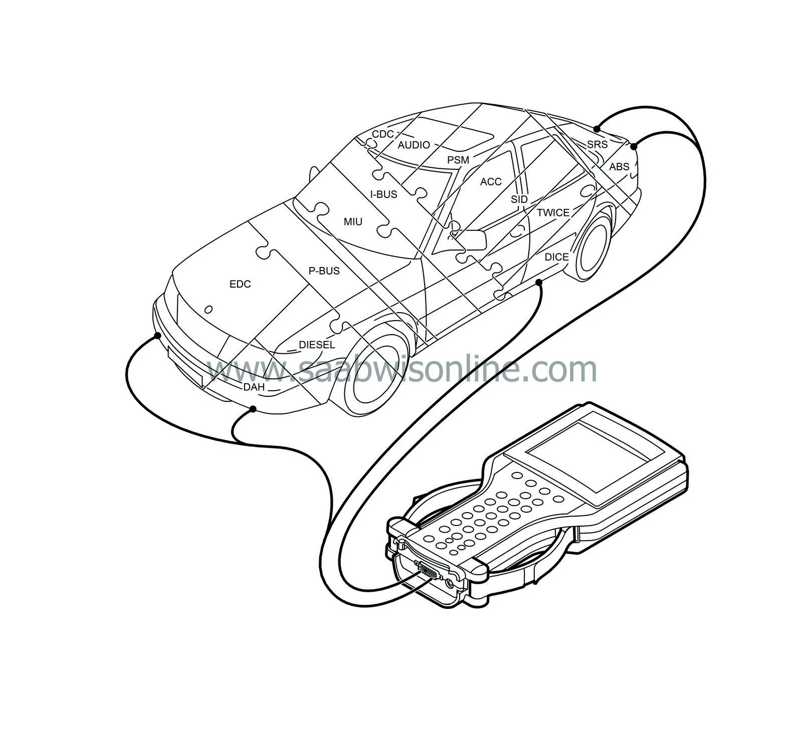
P bus and I bus in the Saab 9-3
The two powertrain systems EDC 15 and the diesel pump are not connected to the I-bus. These systems require
considerably faster
communication to prevent noticeable delays, such as when the EDC requests a new fuel mass per injection or a new injection timing.
Therefore, they are connected through a separate buss called the P-bus (Powertrain Bus). The P-bus has a data transfer rate ten times higher than that of the I-bus.
The P-bus is also connected to the MIU. The MIU is responsible for making the information that is available on one bus also available on the other. Note also that EDC 15 has a separate K-lead to the diagnostic tool.

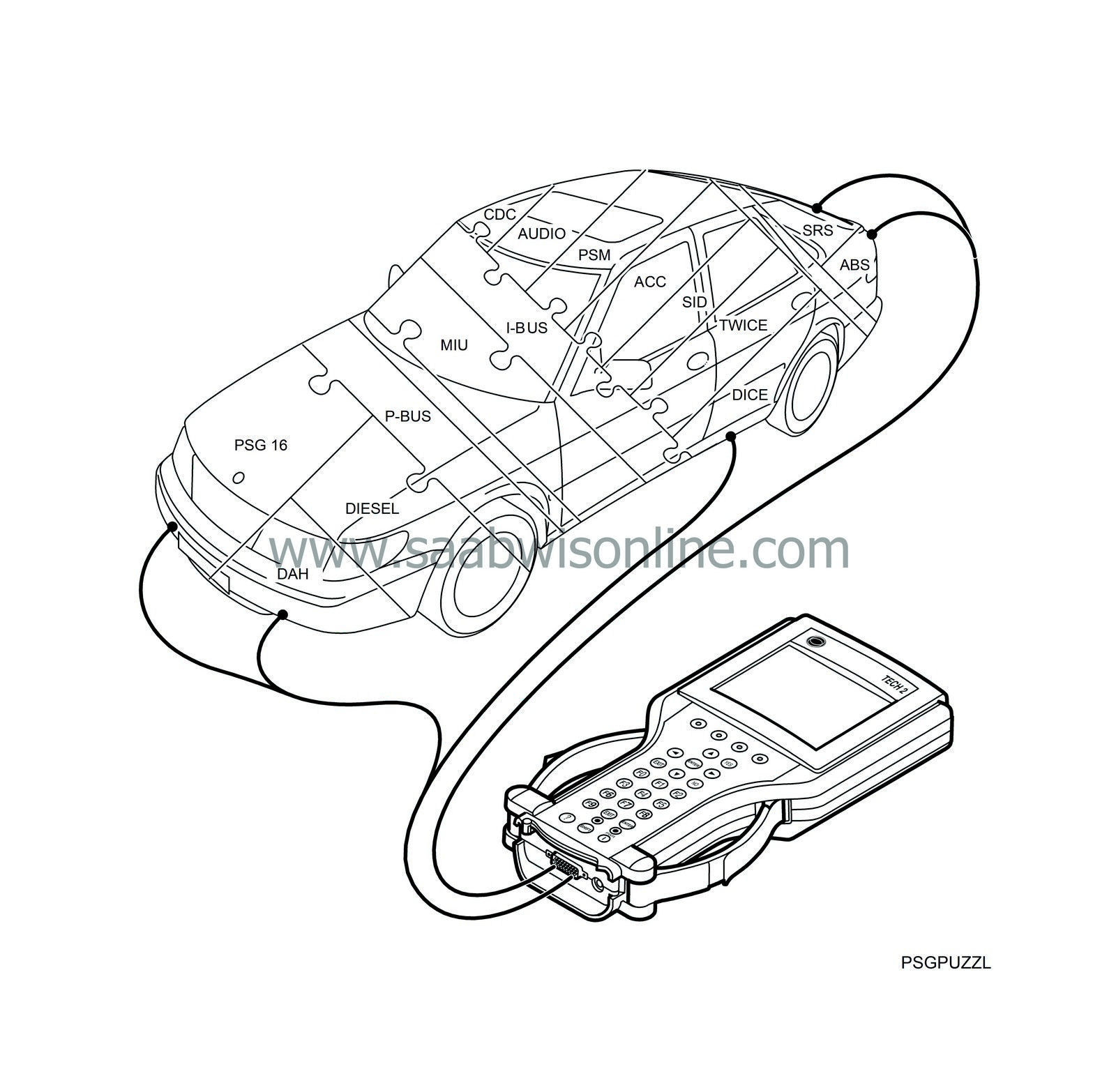
P bus and I bus in the Saab 9-3
The PSG 16 diesel engine control module is not connected to the I-bus. This systems requires
considerably faster
communication to prevent noticeable delays, such as when PSG 16 requests a new fuel mass per injection or a new injection timing.
Therefore, they are connected through a separate buss called the P-bus (Powertrain Bus). The P-bus has a data transfer rate ten times higher than that of the I-bus.
The P-bus is also connected to the MIU. The MIU is responsible for making the information that is available on one bus also available on the other. Note also that PSG 16 has a separate K-lead to the diagnostic tool.


