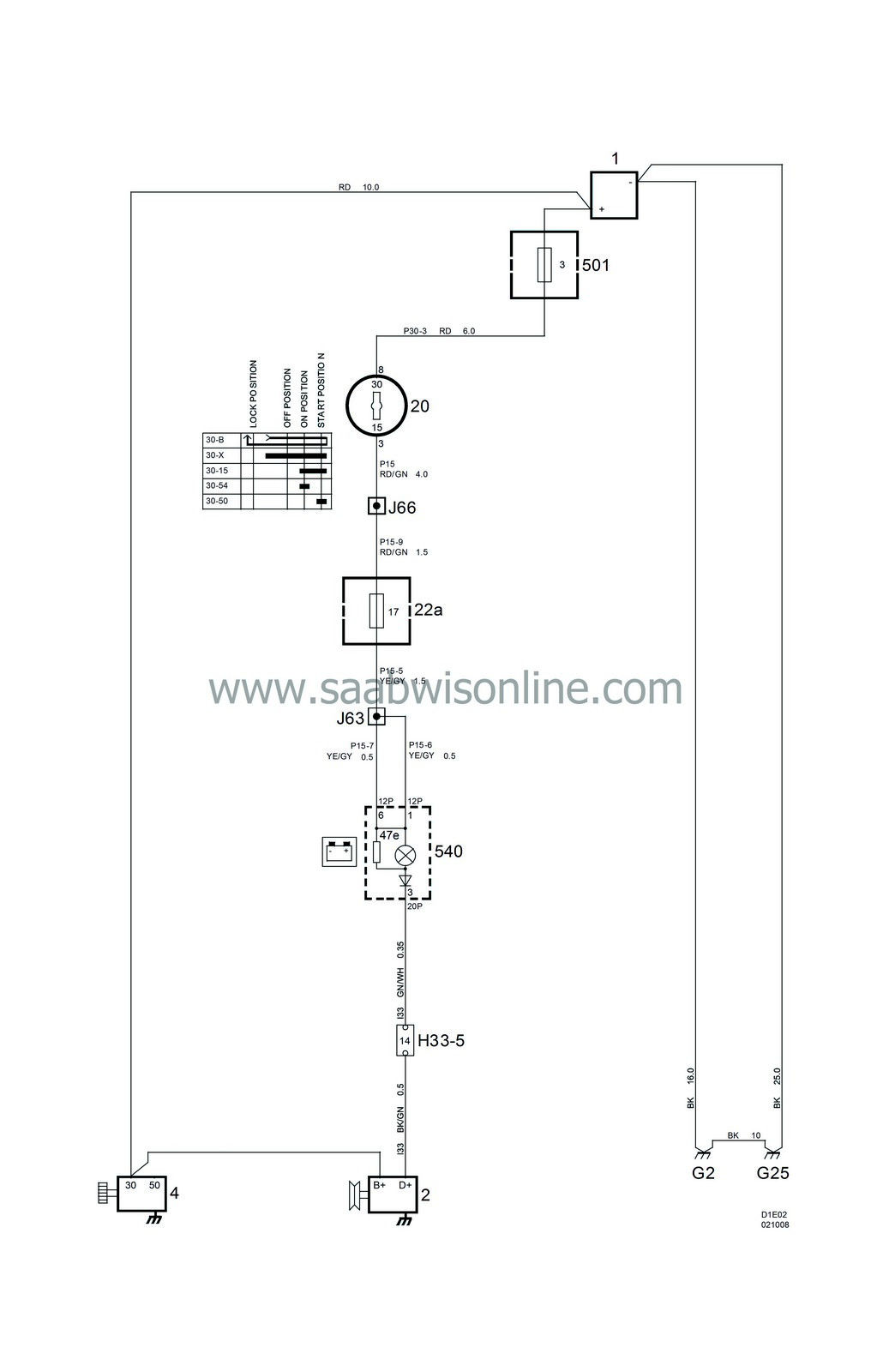
Charging systems
| Charging systems |
| List of components |
| No. | Name Location | Fig. |
|
Components |
||
|
1
|
Battery,
in engine bay |
|
|
2
|
Generator,
on rear RH side of engine |

|
|
4
|
Starter motor,
on rear left side of engine |

|
|
20
|
Ignition switch,
in floor console between the front seats |

|
|
22a
|
Main fuse board, dashboard,
on end of the dashboard by the driver's door |

|
|
47e
|
Warning lamp, charging,
in main instrument unit |
|
|
501
|
Fuse board, maxi fuses,
next to battery |

|
|
540
|
Main instrument unit
in front of driver in dashboard |
c
d |
|
33-pin Connector |
||
|
H33-5
|
LHD:
Grey connector on bulkhead behind glove box
RHD: Grey connector under engine control module. |

|
|
Crimps |
||
|
J63
|
LHD:
Approx. 200 mm from branching of seatbelt warning lamp towards MIU
RHD: About 50 mm from branching point rheostat towards light switch |

|
|
J66
|
LHD:
About 85 mm from branching point grounding point G33 towards control module DICE
RHD: About 30 mm from branching point fuse board towards fuse board |

|
|
Grounding points |
||
|
G2
|
Grounding point, LH structural member (battery),
in engine bay in front of left wheel housing |

|
|
G25
|
Grounding point, gearbox (battery),
in engine bay on gearbox |

|


