Mass air flow sensor
| Mass air flow sensor |
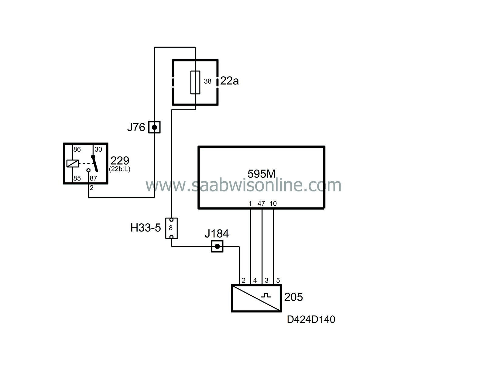
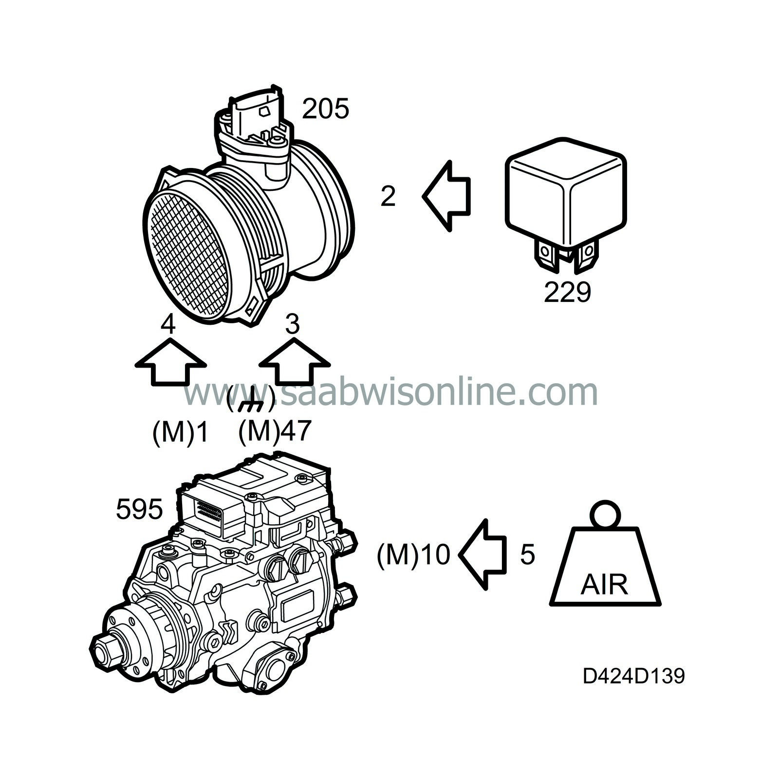
The pins are connected as follows:
| 1. |
Power supply
|
|
| 2. |
Sensor ground
|
|
| 3. |
Power supply
|
|
| 4. |
Air mass voltage
|
|
Measurement is conducted in the following way. Some of the air flow through the mass air flow sensor passes a measuring plate. The surface of this plate is a thin diaphragm of semi-conductor type on which a heating element and a number of temperature sensors are fitted. The heating element is a resistor, which radiates heat when current passes through it. Together with the resistor, there is a temperature sensor that enables the heat in the heating element to be regulated exactly. The temperature of the heating element is dependent on the temperature of the incoming air.
There are two more temperature sensors on the diaphragm, one upstream and one downstream from the heating element as seen from the direction of the airflow. If there is no air flowing past the diaphragm, the temperature will be the same across its entire surface. The two temperature sensors upstream and downstream from the heating element will then detect the same temperature.
When air starts to flow through the mass air flow sensor, the diaphragm upstream from the heating element will cool down, which the temperature sensor on the diaphragm will detect. The temperature of the diaphragm and the temperature sensor downstream from the heating element will be the same as before the airflow started.
By measuring the difference in temperature of the airflow between the two temperature sensors (upstream and downstream), the air mass can be calculated.
The direction of flow can also be determined by taking into account which of the temperature sensors is the warmest and the coldest respectively. All the necessary calculations are carried out in the mass air flow sensor.
The signal, which is available to the engine management control module, consists of the calculated air mass and the temperature of the incoming air.
| Diagnostics, mass air flow sensor |

System reaction to a fault
| • |
As soon as the control module detects a fault:
Limp-home with fuel doses, 30 mg fuel up to 1250 rpm. 20 mg fuel up to 2250 rpm. 0 mg fuel up to 2500 rpm. |
|
| • |
The control module connects the functions "fuel quantity limitation upon system fault", see
Engine torque limitation upon DTC
|
|
| • |
The value on the diagnostic tool for P0100, P0102 and P0103 is1500 mg/combustion.
|
|


