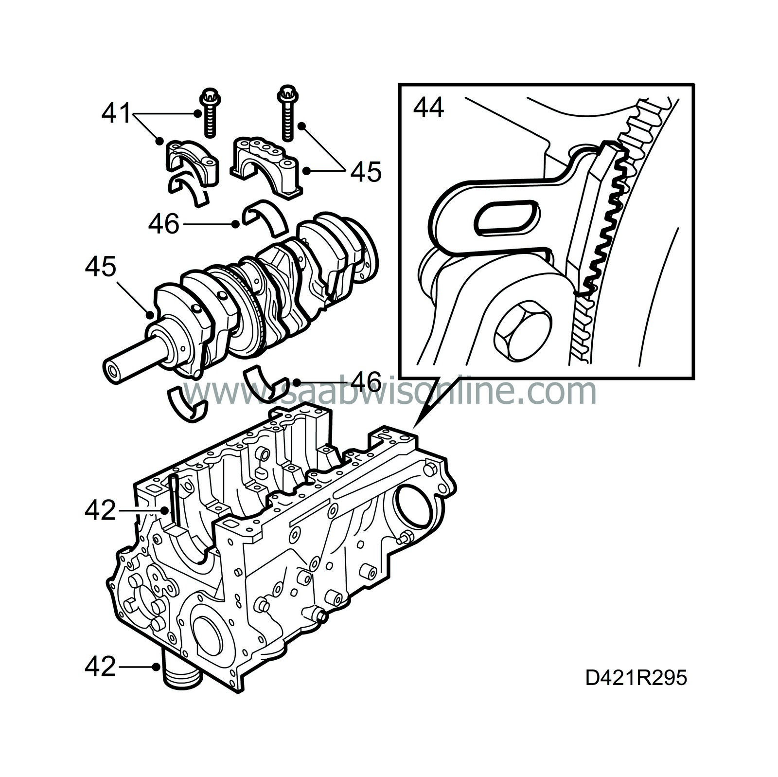
Engine block
| Engine block |
| 1. |
Fit holder 83 94 751 to the engine and lift the power train over to floor stand 78 74 878.
|
|
| 2. |
Drain the engine oil.
|
|
| 3. |
Detach the two fuel lines from the fuel distribution pump.
|
|
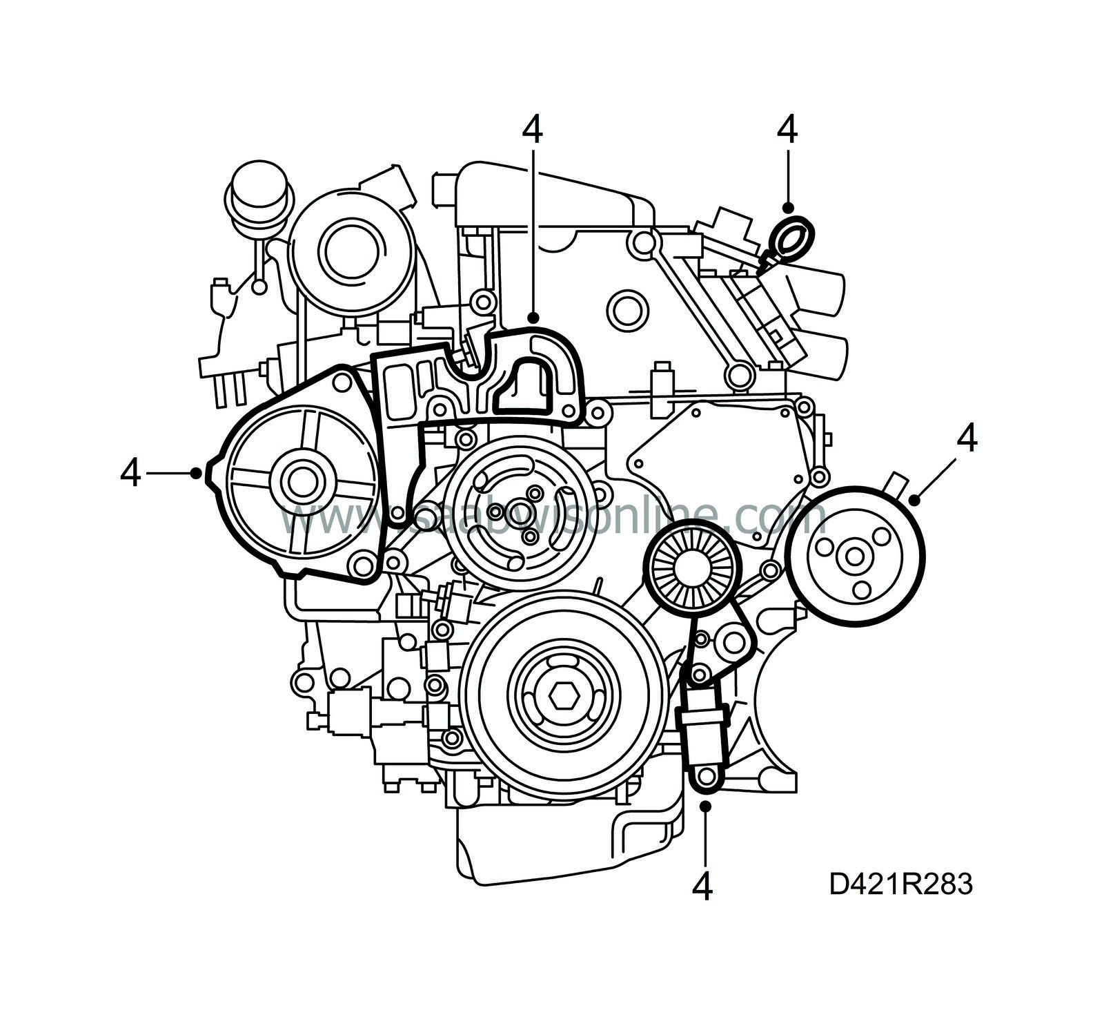
| 4. |
Dismantle the belt tensioner, generator, engine mounting bracket, dipstick and power steering pump with bracket.
|
|
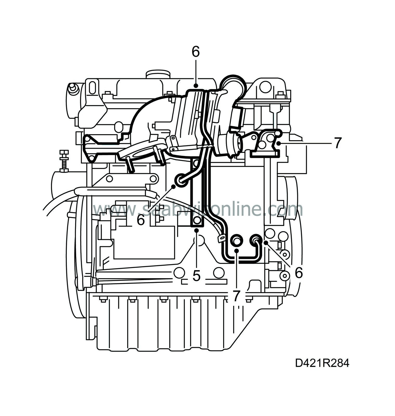
| 5. |
Remove the exhaust manifold support.
|
|
| 6. |
Detach both turbocharger oil pipes from the cylinder block, remove the oil pipe connections from the cylinder block and dismantle the exhaust manifold with turbocharger.
|
|
| 7. |
Remove the generator bracket and engine oil pressure sensor.
|
|
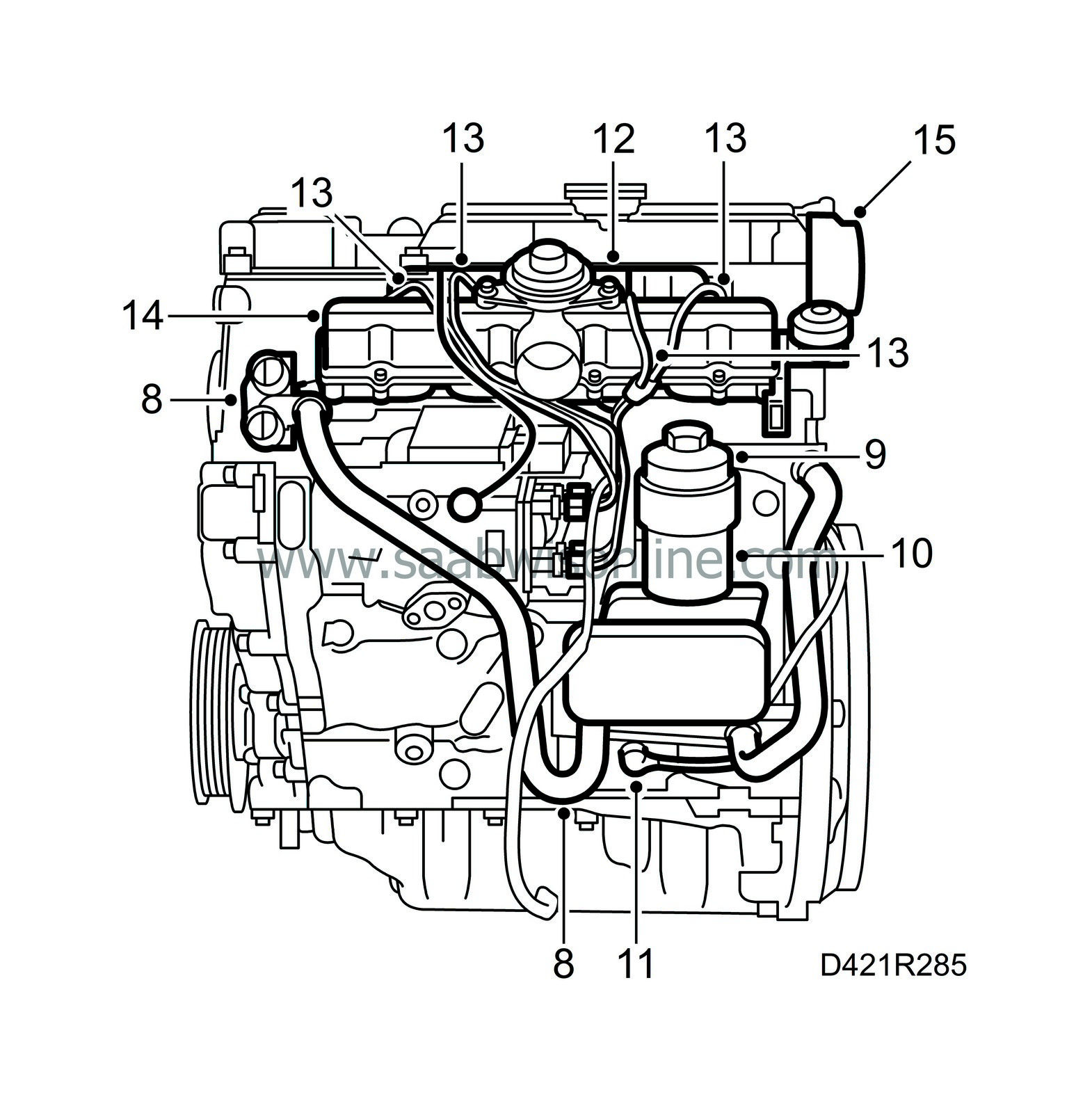
| 8. |
Detach the coolant hose from the thermostat housing and dismantle the thermostat housing.
|
|
| 9. |
Take off the lid on the oil filter housing and remove the oil filter.
|
|||||||
| 10. |
Dismantle the filter housing with heat exchanger and hoses.
|
|
| 11. |
Dismantle the crankshaft position sensor with O-ring.
|
|
| 12. |
Pull off the fuel return hoses.
|
|
| 13. |
Note the position of the fuel rails and their clamps, mark the rails and remove the them.
|
|
| 14. |
Dismantle the upper part of the intake manifold, remove the gasket and dismantle the lower part of the intake manifold.
|
|
| 15. |
Undo the four vacuum pump retaining bolts and carefully lift away the vacuum pump and its adapter.
|
||||||||||
| 16. |
Remove the camshaft cover.

|
|
| 17. |
Remove the bolts on the cover, carefully insert a spatula behind the cover and prise it off.
|
||||||||||
| 18. |
Turn the crankshaft with the centre bolt on the pulley two revolutions until it reaches the mark for top dead centre in cylinder 1. Make sure both cams for cylinder 1 are point up.

|
|
| 19. |
Position inspection gauge 83 95 352 inside the hole for the crankshaft position sensor. Press the tool inwards slightly at the same time as the crankshaft is turned to the zero mark. The tool will then enter a recess in the crankshaft and secure it.
|
|
| 20. |
Make sure the marks on the crankshaft pulley and the timing cover are aligned. Also, the arrow on the single cam chain sprocket on the fuel distribution pump must be aligned with the recess in the pump. Position inspection gauge 83 95 337 inside the hole.
|
|
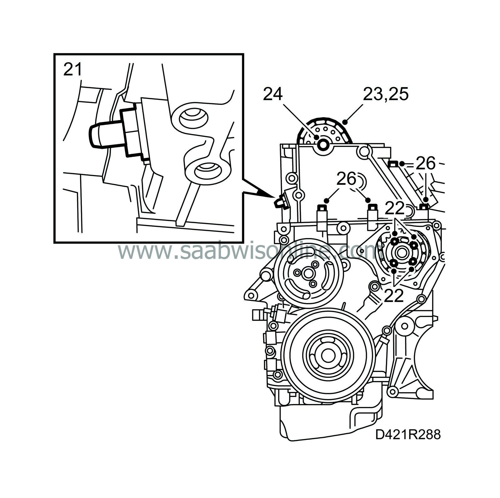
| 21. |
Dismantle the upper timing chain tensioner.
|
|
| 22. |
Remove inspection gauge 83 95 337 and undo the four bolts for the upper timing chain gear.
|
||||||||||
| 23. |
Fasten the timing chain to the camshaft gear.
|
|
| 24. |
Dismantle the camshaft gear using an open spanner in the hexagonal recess on the camshaft as a backstop.
|
|
| 25. |
Pull up the upper timing chain.
|
|
| 26. |
Undo the four bolts securing the cylinder head to the timing cover.
|
||||||||||
| 27. |
Unbolt the cylinder head by undoing the bolts in the illustrated order. Lift the cylinder head
straight up
and lay it in such a way as the fuel injectors, glow plugs or valves do not get damaged.

|
|
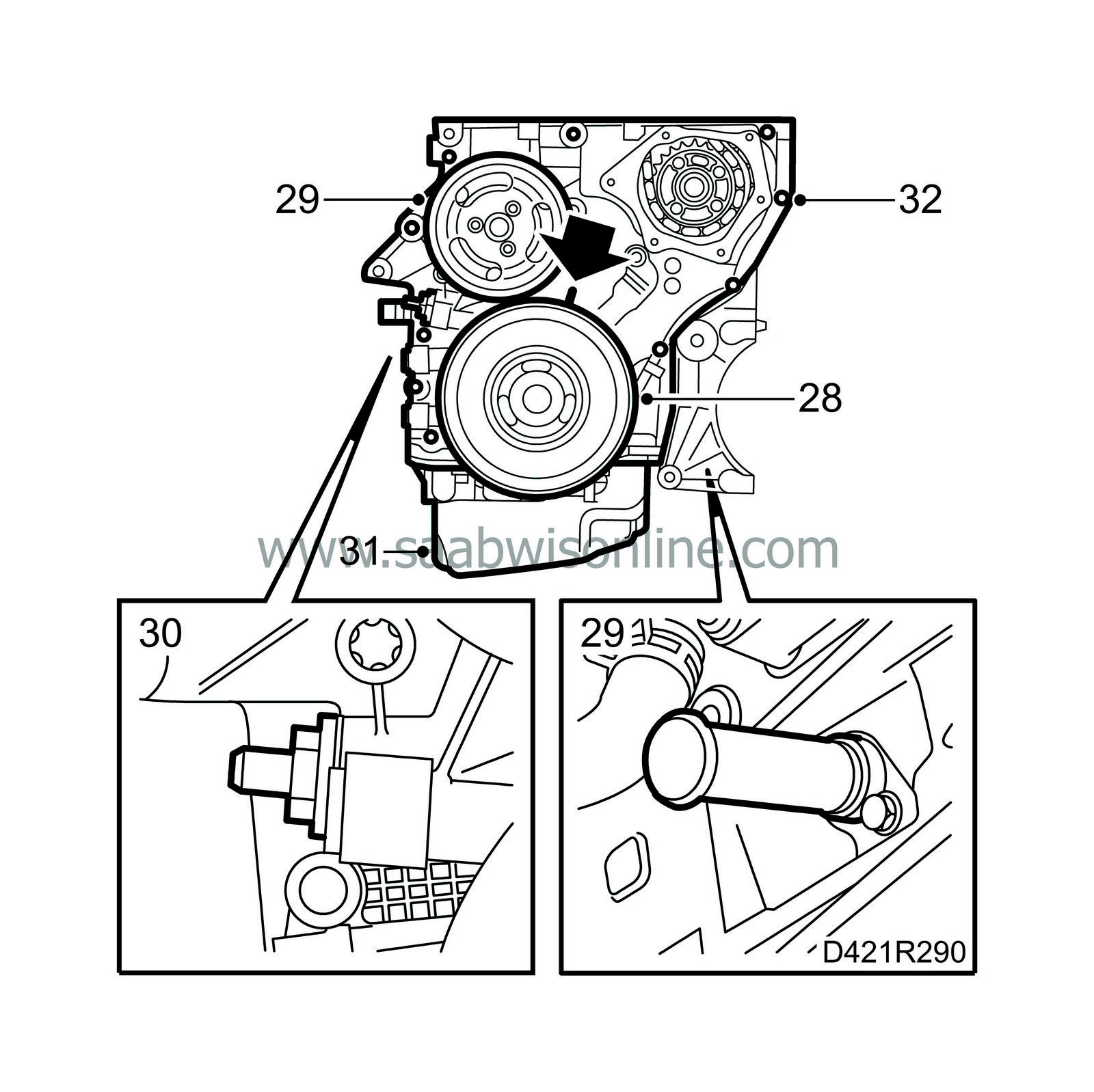
| 28. |
Dismantle the crankshaft pulley with tool 83 95 360 as a backstop.
|
|
| 29. |
Remove the coolant pump pulley and tool 83 95 352.
|
|
| 30. |
Dismantle the lower timing chain tensioner.
|
|
| 31. |
Turn the engine over and dismantle the oil sump.
|
||||||||||
| 32. |
Undo all the bolts on the timing cover.
|
||||||||||
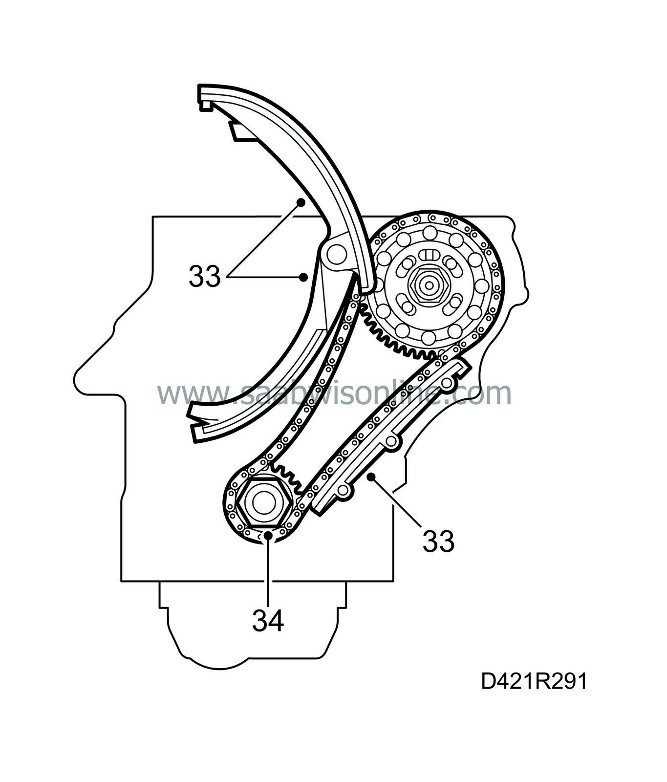
| 33. |
Dismantle all the catenary rules.
|
|
| 34. |
Carefully remove the lower timing chain together with the gears.
|
||||||||||
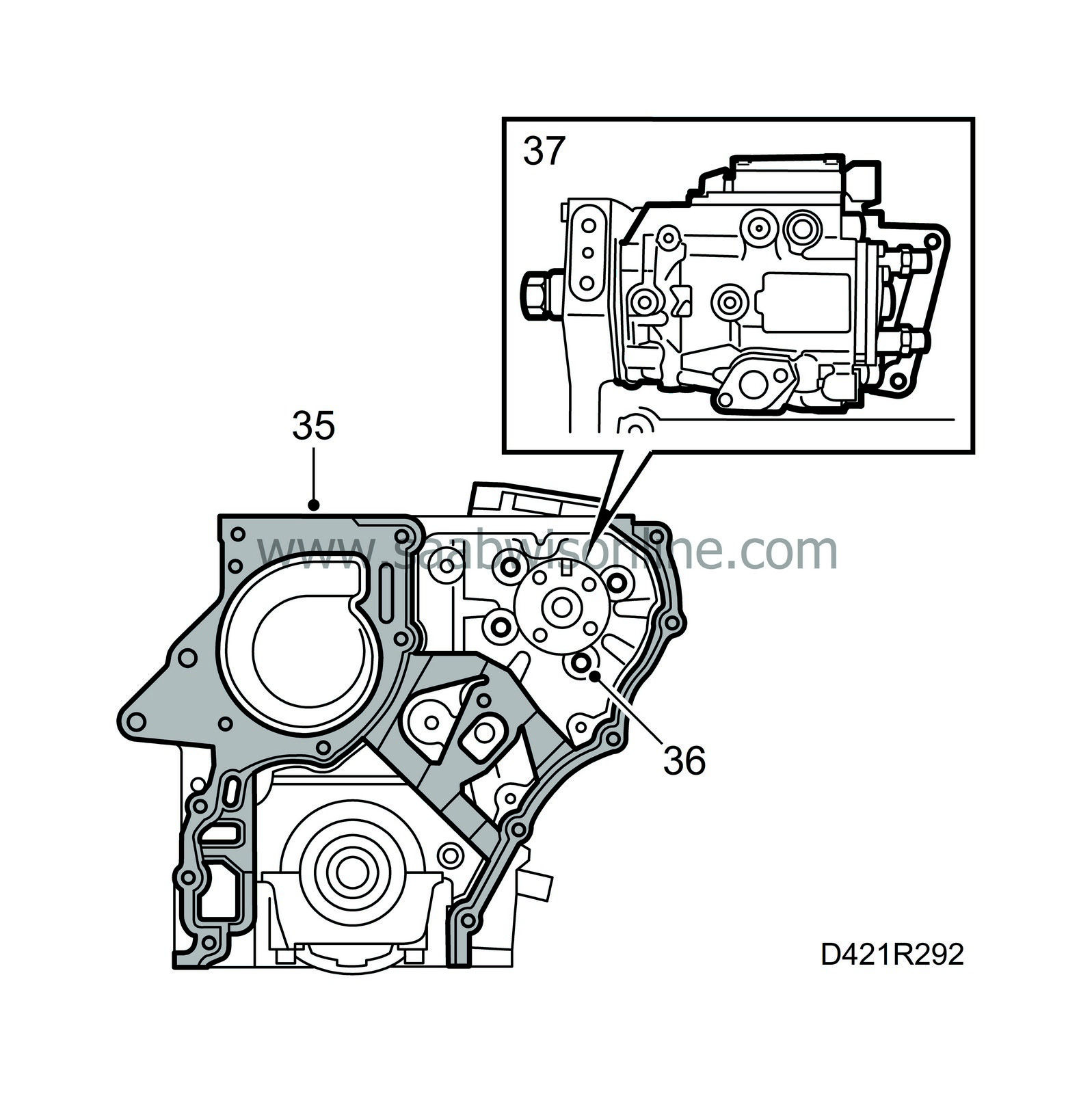
| 35. |
Remove the timing cover gasket.
|
|
| 36. |
Undo the fuel distribution pump retaining bolts on the transmission side.
|
|
| 37. |
Remove the bracket from the fuel distribution pump and the cylinder block, and dismantle the fuel pump.
|
|
| 38. |
Lock the balancer shafts with tool 83 95 469 and remove the cover over the balancer shaft chain transmission.

|
|
| 39. |
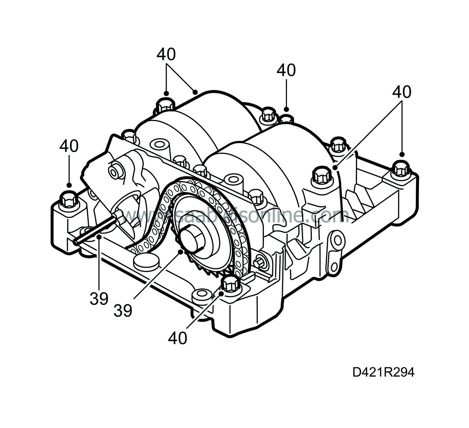
Push back and lock the balancer shaft chain tensioner and remove the sprocket from the balancer shaft.
|
|
| 40. |
Undo the 7 outer bolts and dismantle the balancer shafts as one unit.
|
|
| 42. |
Screw the bolts into the connecting rods and fit protective sleeve 75 19 531 onto the studs. Press or knock the pistons carefully out of the cylinders.
|
|
| 43. |
Dismantle the pressure plate and the clutch disc.
|
|
| 44. |
Fit flywheel locking segment 83 94 868 and remove the flywheel.
|
|
| 45. |
Remove all main bearing caps and lift out the crankshaft.
|
||||||||||
| 46. |
Remove all bearings.
|
|
| 47. |
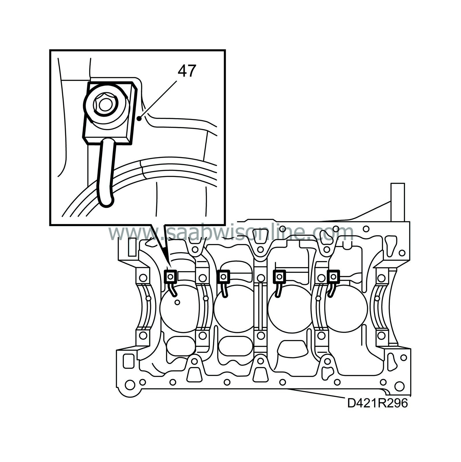
Remove the piston cooling nozzles.
|
|
| Assembling |
| 1. |
Wash all sealing surfaces thoroughly with washing spirit.
|
|
| 2. |
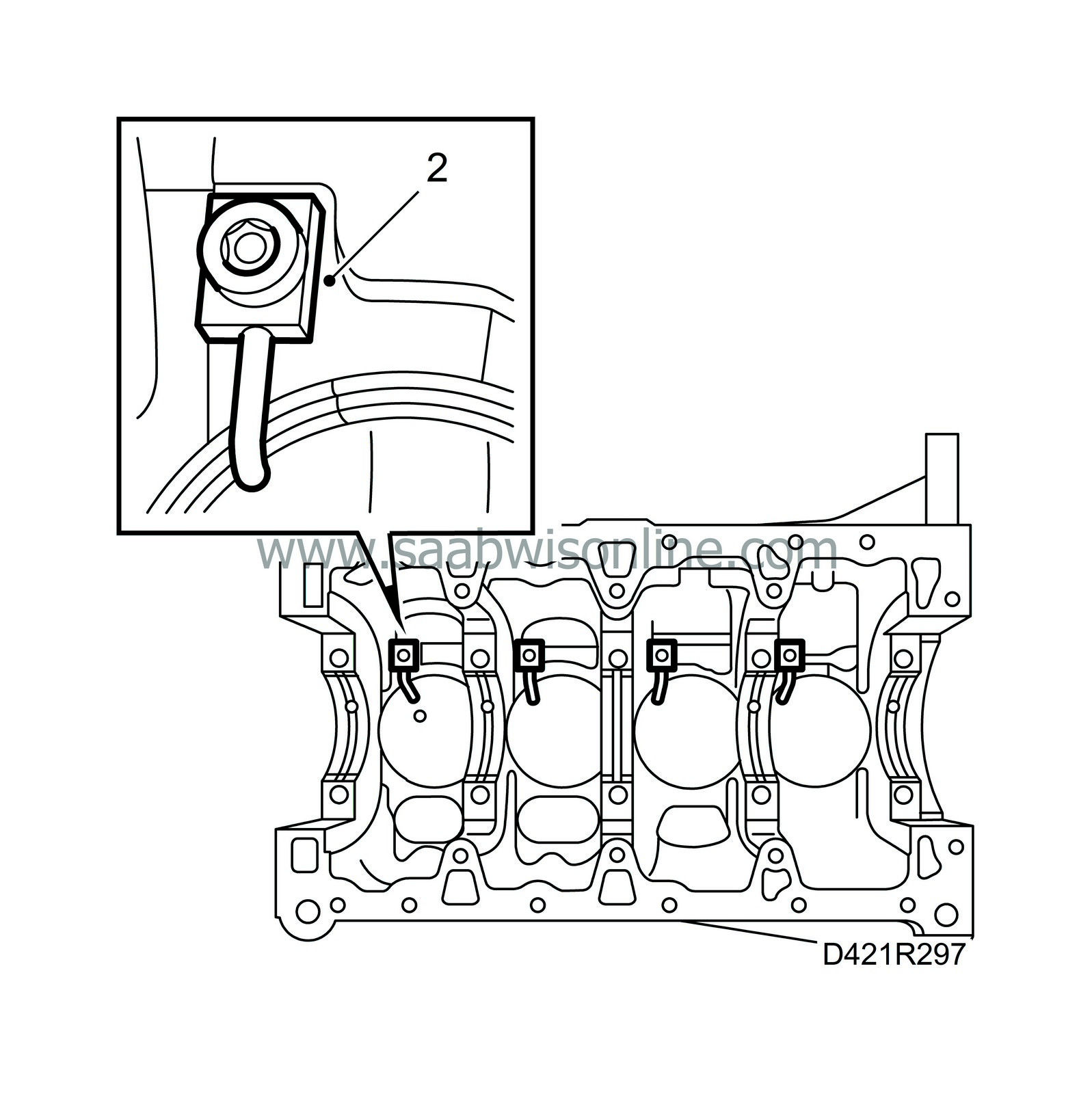
Fit the piston cooling nozzles.
Tightening torque: 22 Nm (16 lbf ft). |
|
| 3. |
Oil in all the main bearings and place them in their correct positions.

|
|
| 4. |
Put the crankshaft in place.
|
||||||||||
| 5. |
Lubricate and fit all main bearing caps in their correct places, making sure that they are the right way round.
Tightening torque 90 Nm (66.5 lbf ft) + 60°. |
|
| 6. |
Lubricate the new rear crankshaft sealing ring with acid-free vaseline and position it on protective sleeve 83 95 402 (KM-934-1).

|
|
| 7. |
Position the sealing ring with protective sleeve and tool 83 95 402 (KM-934-2) onto the crankshaft. Press in the sealing ring with tool 83 95 402 (KM-454-4) until it is flush with the cylinder block.
|
|
| 8. |
Fit the flywheel loosely. Apply Loctite 270D on the bolts. Use flywheel locking segment 83 94 868 and tighten the bolts.
Tightening torque 45 Nm (33 lbf ft) +30°. |
|
| 9. |
Position clutch disc centring mandrel 87 92 327 and the clutch disc.
|
|
| 10. |
Fit the pressure plate.
Tightening torque: 22 Nm (16 lbf ft). |
|
| 11. |
Make sure the working gaps in the piston rings are positioned as illustrated.

|
|
| 12. |
Lubricate the piston rings and the cylinders with engine oil.
|
|
| 13. |
Screw in the bolts in the connecting rods and press protective sleeve 75 19 531 onto the bolt heads to facilitate fitting.
|
|
| 14. |
Turn the crankshaft so that the relevant crank web is at its highest position.
|
|
| 15. |
Fit the piston. The arrow on the top of the piston must be pointing towards the transmission side.
|
|
| 16. |
Lubricate the bearing halves with engine oil and lay them in their respective positions in the connecting rods and caps.
|
|
| 17. |
Note the position of the big-end caps (the heel on the cap pointing towards the flywheel) and fit them with new bolts.
Tightening torque 35 Nm (26 lbf ft) + 45°. |
||||||||||
| 18. |
Fit the balancer shaft unit.
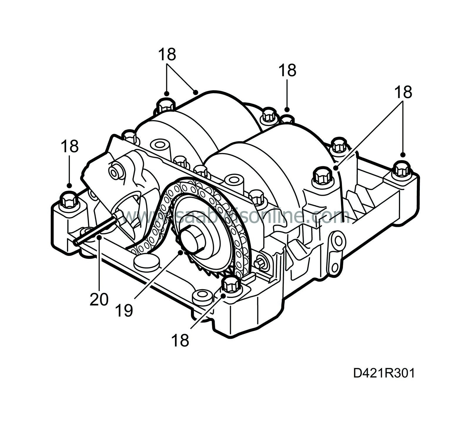
Tightening torque: 20 Nm (15 lbf ft). |
|
| 19. |
Position the sprocket on the balancer shaft and tighten the bolt.
Tightening torque 90 Nm (66.5 lbf ft) +30°. |
|
| 20. |
Release the chain tensioner.
|
|
| 21. |
Fit the cover and remove the locking tool from the balancer shafts.
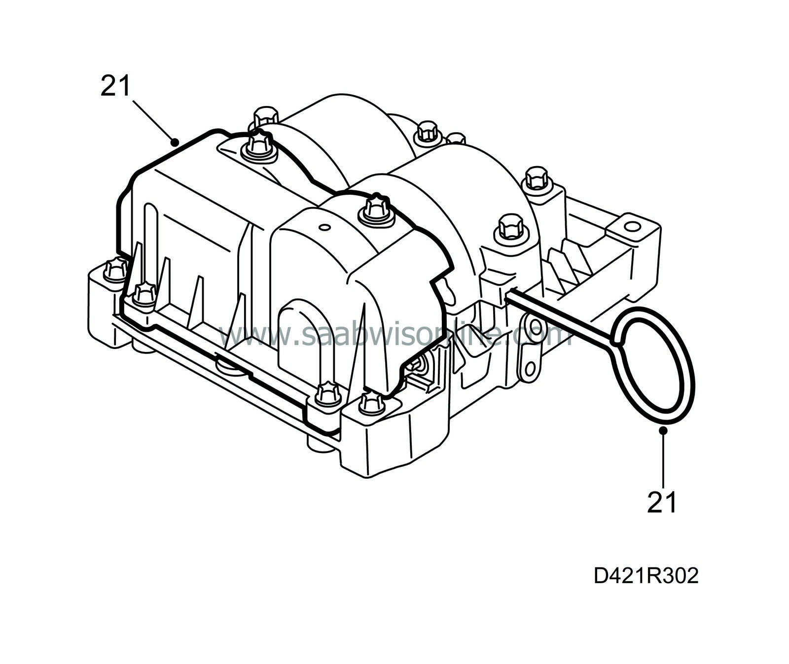
|
|
| 22. |
Fit a new O-ring on the fuel distribution pump, lubricate the O-ring with acid-free vaseline, position the pump on the cylinder block and fit the bracket to the pump.
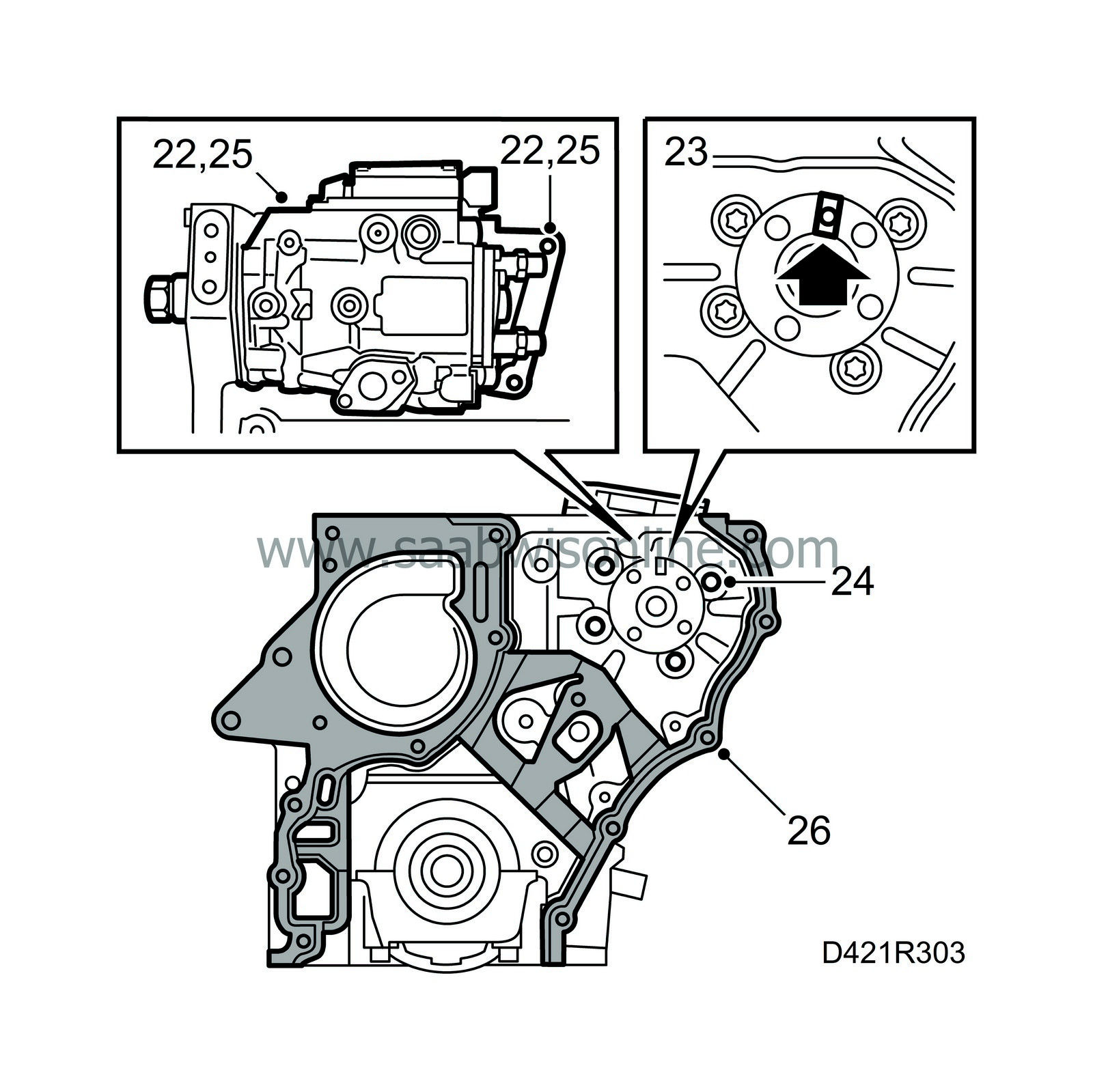
Tightening torque: 20 Nm (15 lbf ft). Position the bolts through the hole in the timing cover but do not tighten them. |
|
| 23. |
Position inspection gauge 83 95 337 in the recess in the fuel distribution pump.
|
|
| 24. |
Tighten the bolts on the fuel distribution pump to the transmission end of the engine.
Tightening torque: 25 Nm (18.5 lbf ft). |
|
| 25. |
Tighten the bolts securing the bracket to the cylinder block.
Tightening torque: 20 Nm (15 lbf ft). |
|
| 26. |
Fit a new gasket on the cylinder block.
|
|
| 27. |
Remove the inspection gauge from the fuel distribution pump.
|
|
| 28. |
Refit the gears on the crankshaft and fuel distribution pump together with the lower timing chain. The lower part of the timing chain must be taut.

|
|
| 29. |
Check with gauge 83 95 337 that the recess in the fuel distribution pump flange is aligned with the hole in the pump. Leave the gauge in place.
|
|
| 30. |
Refit all the catenary rules.
|
|
| 31. |
Fit the timing cover with the bolts in their original positions.

Tightening torque: 20 Nm (15 lbf ft). |
|
| 32. |
Check that there are no impurities or other foreign matter in the sump and clean the sealing surfaces with benzene.

|
|
| 33. |
Turn over the engine and apply sealant 87 81 841 to the mating surfaces, see illustration.
|
|
| 34. |
Place a steel rule against the engine sealing surface to the gearbox to guide the position of the oil sump and fit it with new gaskets.
Tightening order: 1 Tighten all bolts by hand. 2 Tighten the bolts to 20 Nm (15 lbf ft) |
|
| 35. |
Refit the oil plug with a new seal.
Tightening torque: 18 Nm (13 lbf ft). |
|
| 36. |
Fit the chain tensioner for the lower timing chain with a new gasket.
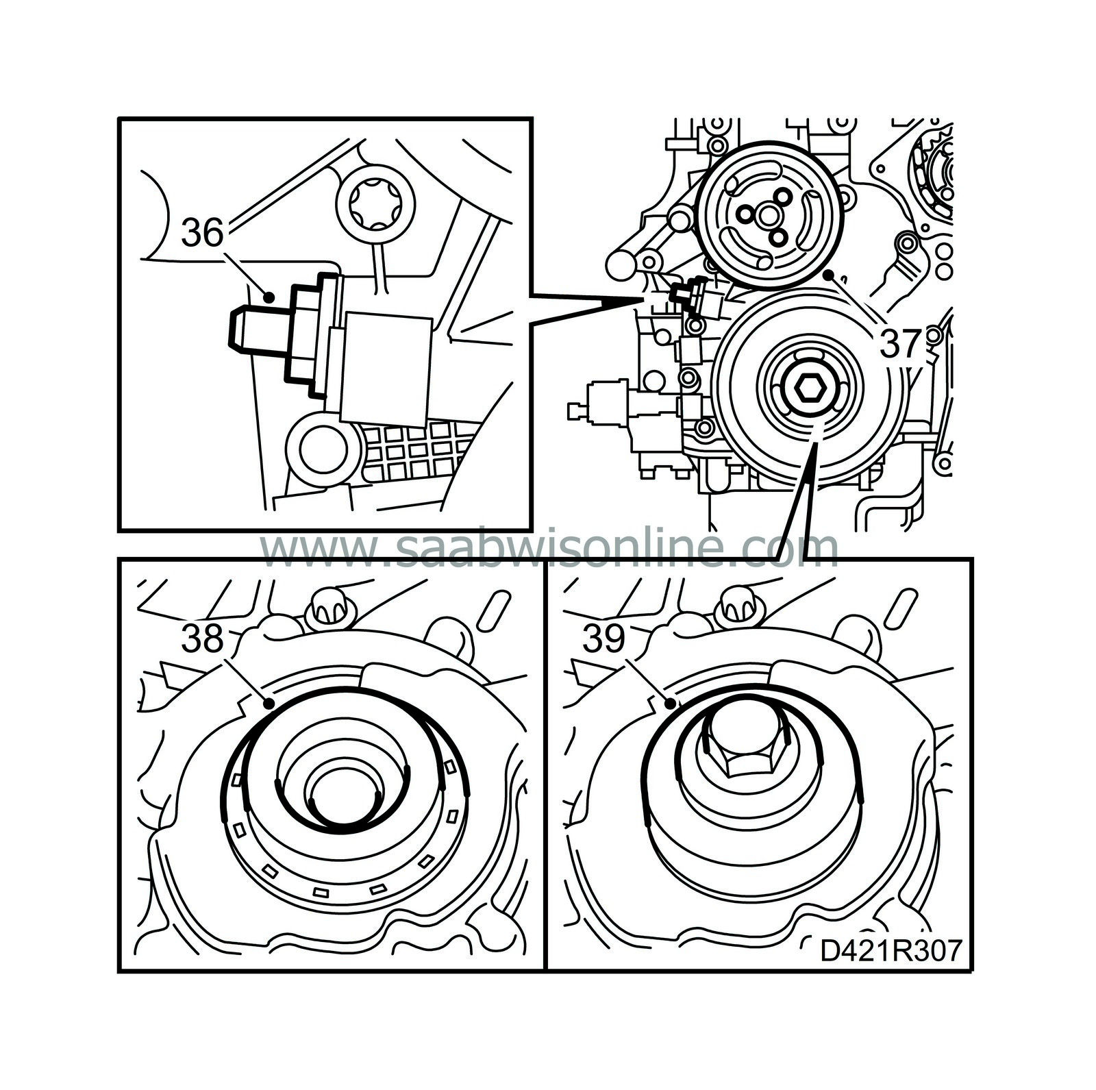
Tightening torque: 60 Nm (44 lbf ft). |
|
| 37. |
Fit the coolant pump belt pulley.
Tightening torque: 20 Nm (15 lbf ft). |
|
| 38. |
Lubricate the new front crankshaft sealing ring with acid-free vaseline and position it on protective sleeve 83 95 410 (KM-935-1).
|
|
| 39. |
Position the sealing ring with protective sleeve and tool 83 95 410 (KM-935-2) on the crankshaft. Press in the sealing ring using the bolt for the crankshaft belt pulley until it is flush with the timing cover.
|
|
| 40. |
Fit the crankshaft belt pulley with a new bolt. Use tool 83 95 360 as a backstop.
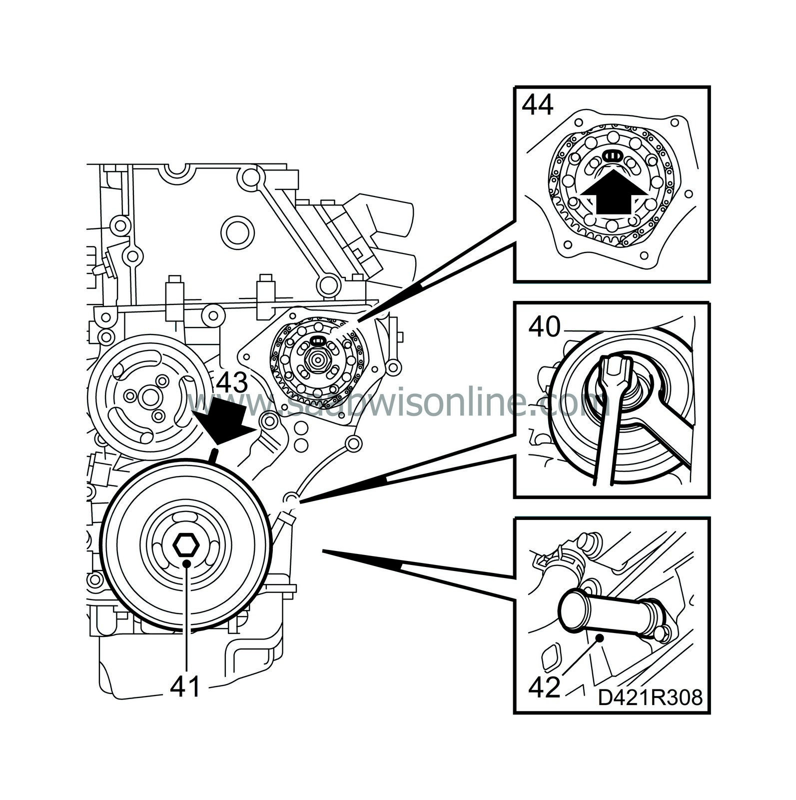
Tightening torque 150 Nm (111 lbf ft) + 45°. |
|
| 41. |
Turn the crankshaft with the centre bolt on the belt pulley until it is just before the mark for top dead centre in cylinder 1.
|
|
| 42. |
Position inspection gauge 83 95 352 inside the hole for the crankshaft position sensor. Press the tool inwards slightly at the same time as the crankshaft is turned to the zero mark. The tool will then enter a recess in the crankshaft and secure it.
|
|
| 43. |
Make sure the marks on the crankshaft belt pulley and the timing cover are aligned.
|
|
| 44. |
Position inspection gauge 83 95 337 in the recess in the fuel distribution pump.
|
|
| 45. |
Check with a steel rule that the sealing surfaces on the cylinder head and cylinder block are plane and not damaged.
|
|
| 46. |
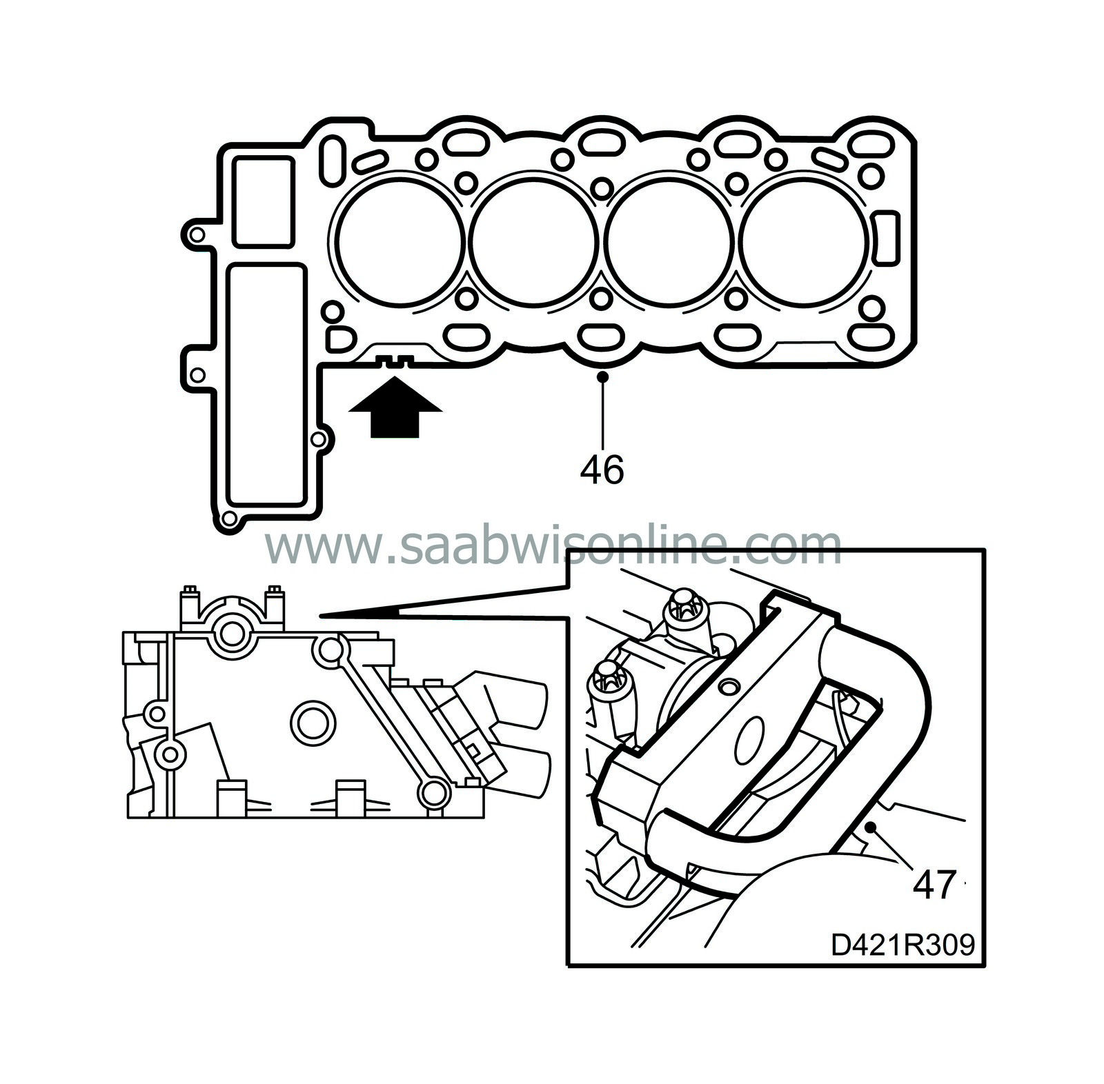
Fit a new gasket having the same thickness marking as the old gasket on the cylinder head. Gaskets with 1 notch (see arrow in illustration) are 1.3 mm thick, gaskets with 2 notches are 1.4 mm thick.
|
|
| 47. |
Position inspection gauge 83 95 386 on the camshaft and cylinder head. The camshaft can be turned slightly if necessary with an open spanner in the hexagonal recess on the camshaft at the same time as the gauge is put into the correct position.
|
|
| 48. |
Position the cylinder head on the cylinder block and tighten the cylinder head with new bolts in the order shown in the illustration.

Tightening torques Stage I: 25 Nm (18.5 lbf ft) Stage II: 65° Stage III: 65° Stage IV: 65° Stage V: 65° |
||||||||||
| 49. |
Tighten the bolts on the timing cover as previously fitted.
Tightening torque: 20 Nm (15 lbf ft). |
|
| 50. |
Remove inspection gauge 83 95 337.
|
|
| 51. |
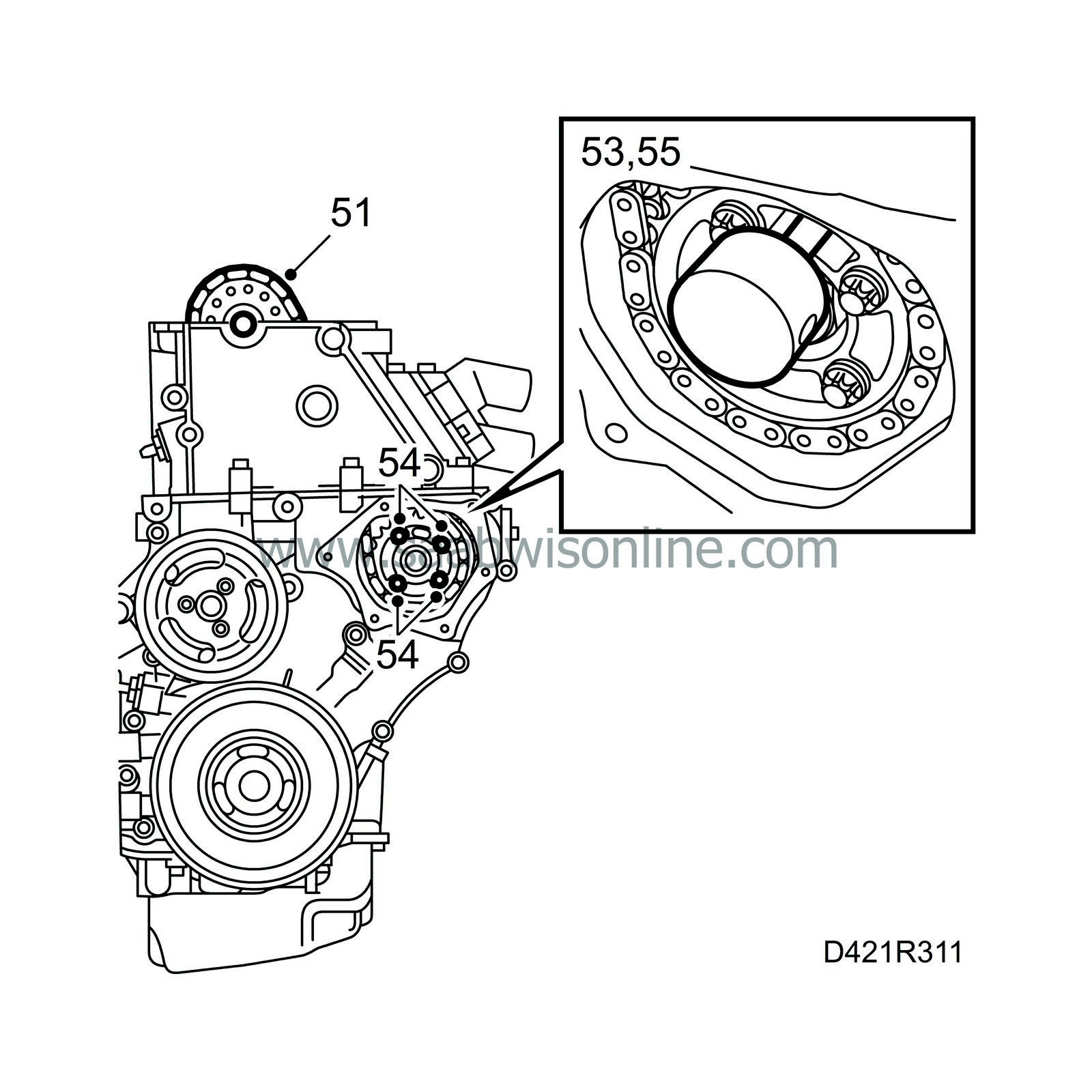
Position the camshaft gear so that is runs easily on the camshaft and fit it with a new bolt. Tighten by hand.
|
||||||||||
| 52. |
Fit the upper timing chain with gear on the fuel pump shaft and secure the gear on the shaft without tightening the bolts.
|
|
| 53. |
Position inspection gauge 83 95 337 in the recess in the fuel distribution pump.
|
|
| 54. |
Remove inspection gauge 83 95 337 and tighten the bolts securing the timing chain gears to the fuel distribution pump.
Tightening torque: 20 Nm (15 lbf ft). |
|
| 55. |
Reposition the inspection gauge 83 95 337 in the recess on the fuel distribution pump.
|
|
| 56. |
Fit the adapter for the timing chain adjuster 83 95 394 on the camshaft gear and the timing chain adjuster on the cylinder head.

|
|
| 57. |
Secure the position of the adapter on the camshaft gear by turning it slightly anticlockwise with a ratchet handle. Tighten the adjuster screw on the tool.
|
||||||||||
| 58. |
Tighten the bolt for the camshaft gear using an open spanner as backstop in the hexagonal recess on the camshaft.
Tightening torque 90 Nm (66.5 lbf ft) +60°. |
|
| 59. |
Fit the chain tensioner for the upper timing chain with a new gasket.
Tightening torque: 60 Nm (44 lbf ft). |
|
| 60. |
Remove all tools and gauges.
|
|
| 61. |
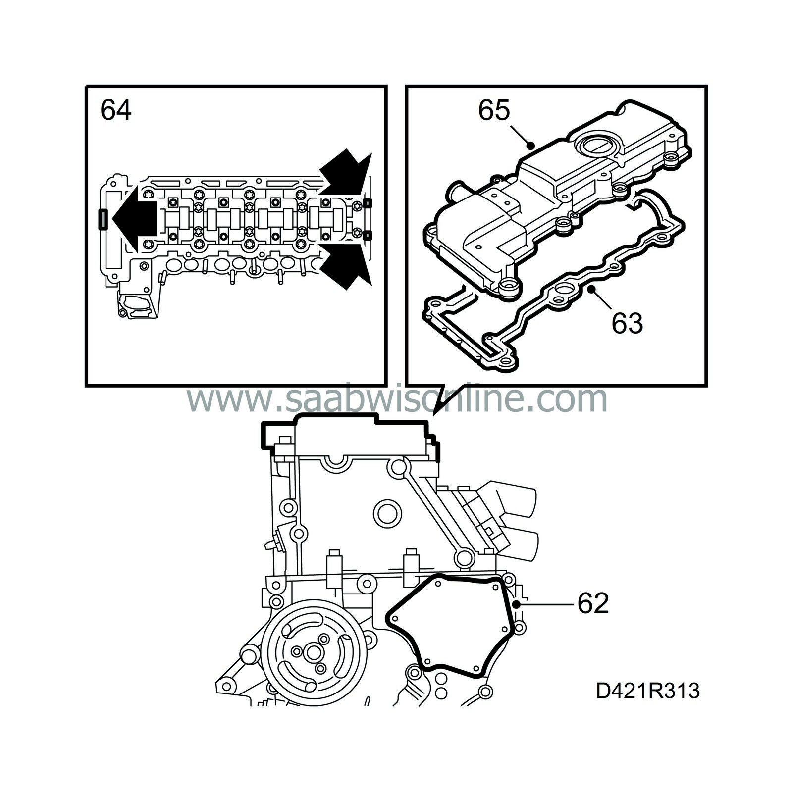
Cover the opening in the timing cover with a lint-free cloth and remove any remains from the old gasket from the sealing surface. Clean also the sealing surface on the cap.
|
|
| 62. |
Apply a string of silicone sealant about 2 mm thick on the cap, remove the cloth from the timing cover and fit the cap.
Tightening torque: 6 Nm (4.5 lbf ft). |
|
| 63. |
Position a new gasket on the camshaft cover. There are sleeves on the bolts on which the gasket fits.
|
|
| 64. |
Apply sealing compound 87 81 841 to the sealing surface, see illustration.
|
|
| 65. |
Position the transmission cover on the cylinder head and tighten the bolts.
Tightening torque: 8 Nm (6 lbf ft). |
|
| 66. |
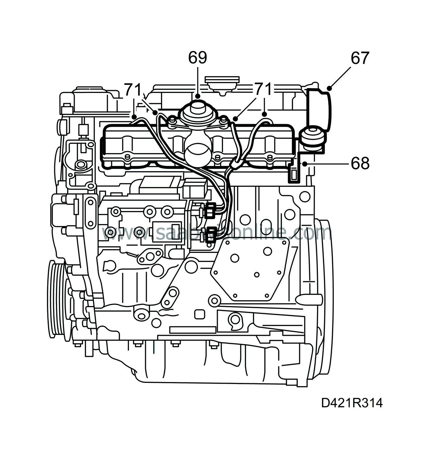
Clean the sealing surfaces on the vacuum pump.
|
|
| 67. |
Fit a new gasket on the vacuum pump and fit the pump together with the adapter.
Tightening torque: 8 Nm (6 lbf ft). |
||||||||||
| 68. |
Fit a new gasket on the cylinder head and fit the lower part of the intake manifold with new nuts.
Tightening torque: 20 Nm (15 lbf ft). |
|
| 69. |
Fit a new gasket on the lower part of the intake manifold and fit the upper part.
Tightening torque 10 Nm (7 lbf ft). |
|
| 70. |
Check the fuel rail connecting cones and replace if necessary.
|
|
| 71. |
Attach the fuel rails with clamps in their original positions.
Tightening torque: 25 Nm (18.5 lbf ft). |
|
| 72. |
Check the condition of the fuel return hoses and joints and replace if necessary.

|
|
| 73. |
Connect the fuel return hoses to the fuel bridges. Pull off the connection on the fuel pump and connect pressure/vacuum pump 30 14 883. Pump up a vacuum of 750 mbar and wait for 1 minute. Make sure the dial on the tool has not moved.
If a leak is detected, the fuel bridges must be inspected individually. Remove the fuel bridge with the leak, change the seal and refit the fuel bridge. Make sure there are no more leaks. See Fuel bridge. |
|
| 74. |
Fit the crankshaft position sensor with a new O-ring.
Tightening torque: 8 Nm (6 lbf ft). |
|
| 75. |
Fit the oil filter housing with a new gasket.
Tightening torque: 20 Nm (15 lbf ft). |
|
| 76. |
Fit a new oil filter and tighten the lid on the oil filter housing.
Tightening torque: 25.5 Nm (19 lbf ft). |
|||||||
| 77. |
Fit the thermostat housing.
Tightening torque: 8 Nm (6 lbf ft). |
|
| 78. |
Attach the hose to the thermostat.
|
|
| 79. |
Fit the generator bracket.

Tightening torque: 20 Nm (15 lbf ft). |
|
| 80. |
Fit the engine oil pressure sensor.
Tightening torque: 30 Nm (22 lbf ft). |
|
| 81. |
Fit the exhaust manifold with turbocharger.
Tightening torque: 22 Nm (16 lbf ft). |
|
| 82. |
Fit the connectors for the turbocharger oil pipes on the cylinder block.
|
|
| 83. |
Connect the turbocharger oil return pipe to the cylinder block.
Tightening torque: 30 Nm (22 lbf ft). |
|
| 84. |
Connect the turbocharger oil delivery pipe to the cylinder block.
Tightening torque: 20 Nm (15 lbf ft). |
|
| 85. |
Put the exhaust manifold support back in place and tighten the screws.
Tightening torque: 25 Nm (18.5 lbf ft). |
|
| 86. |
Fit the power steering pump with bracket.

|
|
| 87. |
Fit the dipstick.
|
|
| 88. |
Fit the engine mounting bracket to the timing cover.
Tightening torque: 47 Nm (35 lbf ft). |
|
| 89. |
Fit the generator.
Tightening torque: 35 Nm (26 lbf ft). |
|
| 90. |
Fit the belt tensioner, tightening the top bolt first.
Tightening torque: 42 Nm (31 lbf ft). Tighten the bottom bolt. Tightening torque: 23 Nm (17 lbf ft). |
|
| 91. |
Connect the fuel lines to the fuel distribution pump with new seals.

Tightening torque: 25 Nm (18.5 lbf ft). |
|
| 92. |
Hook up lifting beam 83 92 409 and lift the engine from the stand. Remove the holder.
|
|


