Power train
| Power train |
| To remove |
|
||||||||||
| 1. |
Place covers on the wings, detach the battery vent hose and remove the battery.
|
|
| 3. |
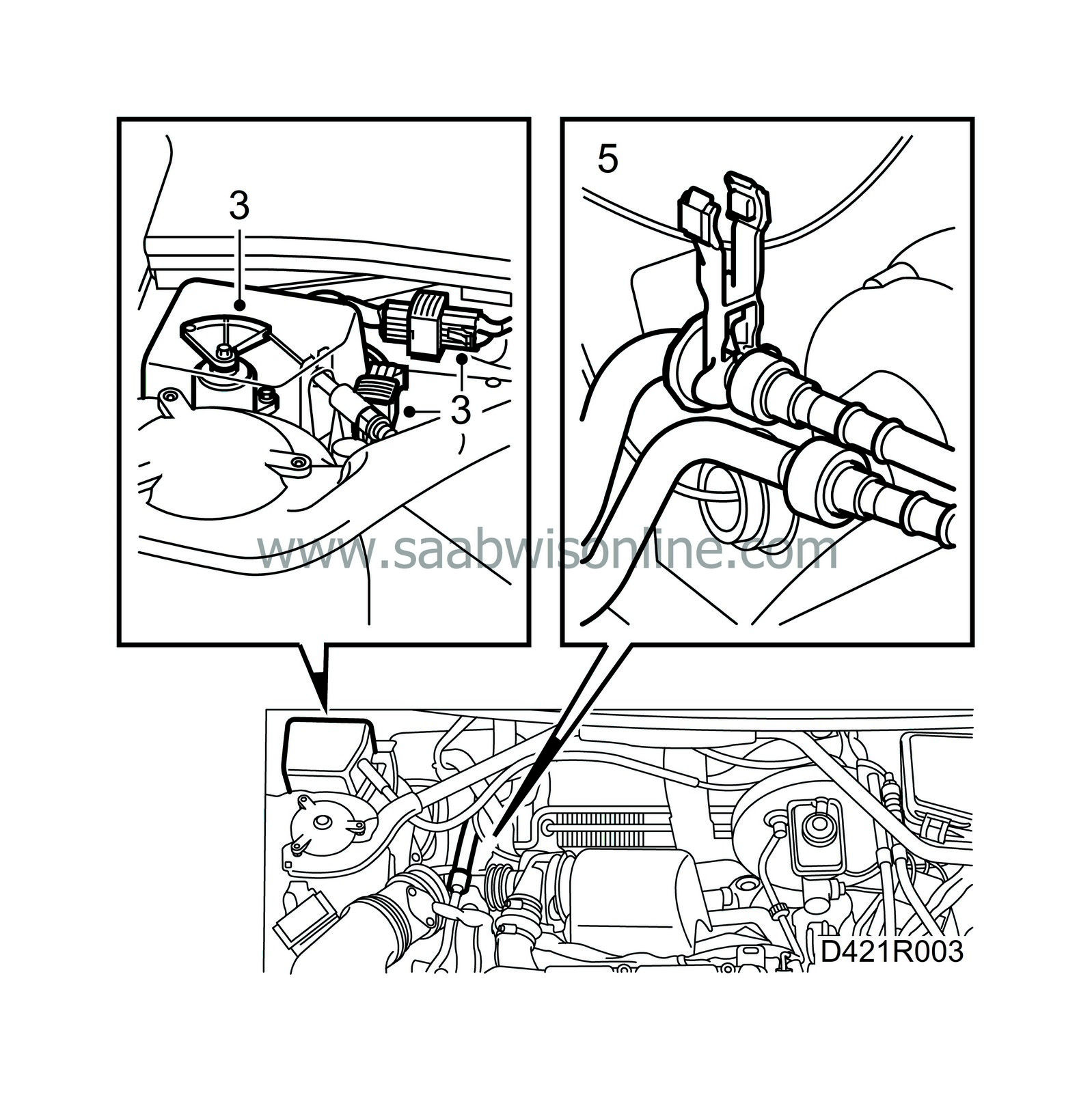
Unplug the connector and remove the accelerator pedal position sensor.
|
|
| 4. |
Remove the cover and the lid on the expansion tank.
|
|||||||||||||||||||||||||||||||||
| 5. |
Remove and seal the fuel hoses. Use tool 83 95 261.
|
|
| 6. |
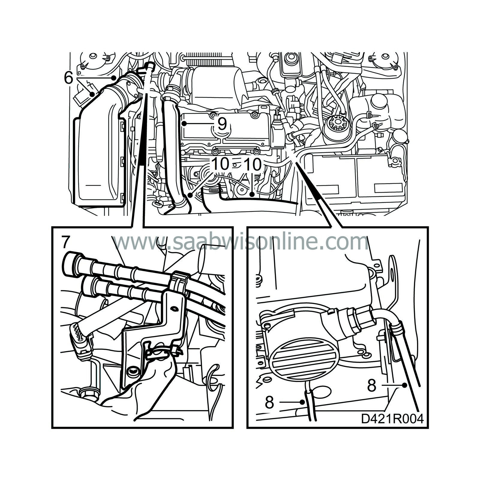
Remove the air cleaner with mass air flow sensor and hoses from the turbocharger and camshaft cover. Seal the openings in the turbocharger.
|
|
| 7. |
Unplug the connector at the bulkhead partition, pull out the wiring harness through the grommet to the engine bay. Cut the fasteners and place the harness on the engine. Detach the fuel lines from their mountings and remove the wiring harness and bracket.
|
|
| 8. |
Detach the vacuum hoses from the vacuum pump.
|
|
| 9. |
Remove the turbo delivery pipe (2 bolts under the wiring harness).
|
|
| 10. |
Remove the hoses on the charge air cooler and intake manifold.
|
|
| 11. |
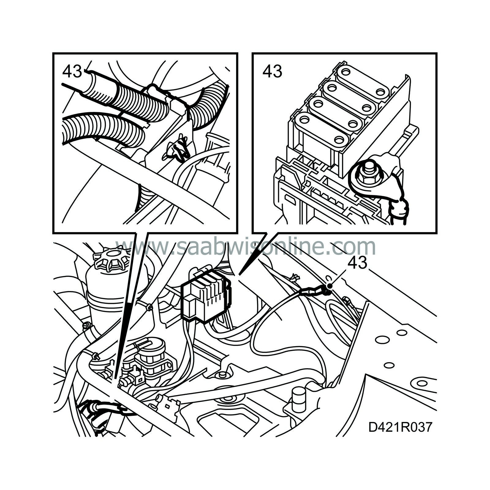
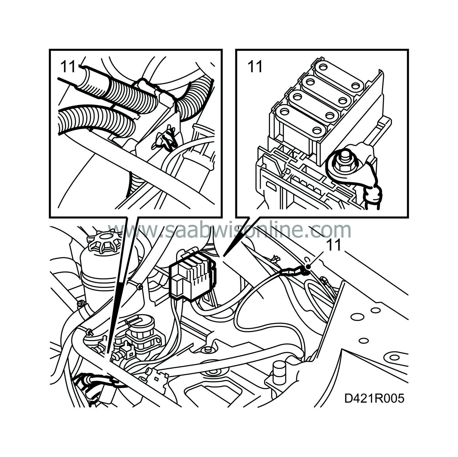
Take off the lid on the MAXI fuse retainer, disconnect the positive cable from the positive connection box and undo the ground cable on the body. Undo the positive and negative cable fasteners.
|
|
| 12. |
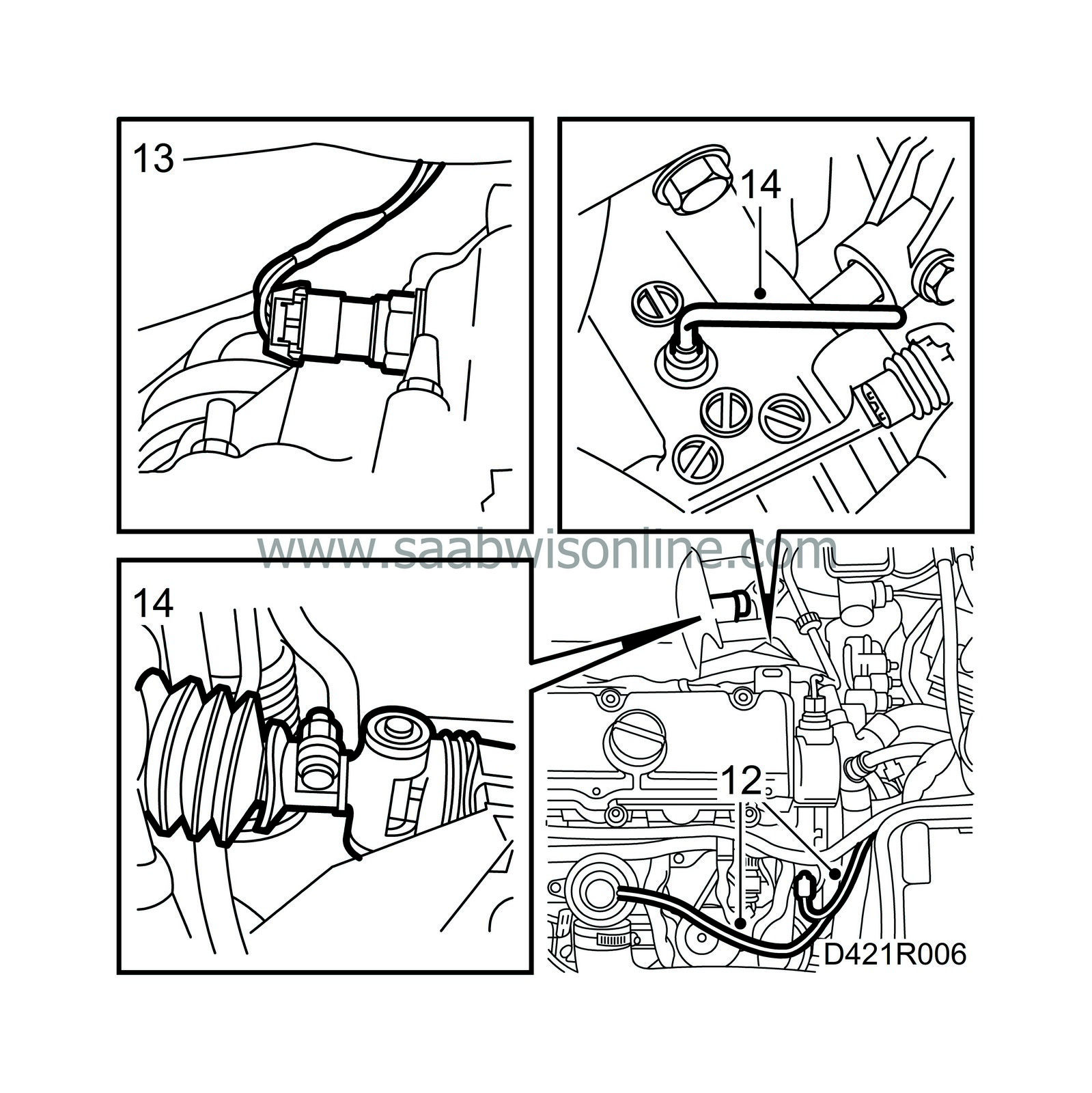
Detach the vacuum hoses from the EGR and swirl throttle valves.
|
|
| 13. |
Detach the reversing light connector.
|
|
| 14. |
Engage 4th gear, remove the plug in the gearbox and fit locking pin 87 92 335. Undo the nut on the gear selector rod and push forward the selector lever.
|
|
| 15. |
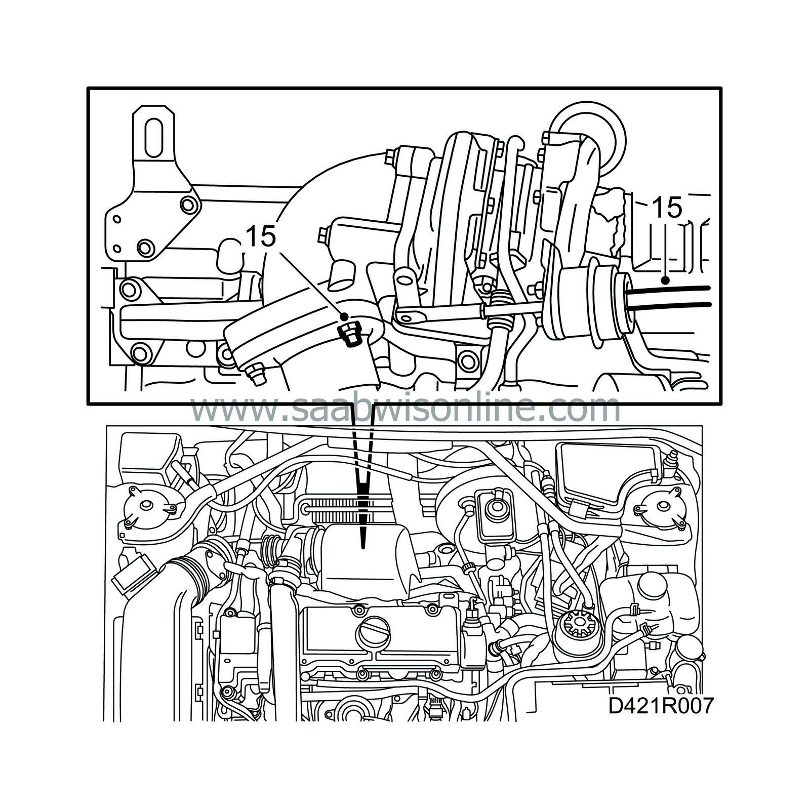
Undo the centre nut at the rear securing the front exhaust pipe to the turbocharger and detach the vacuum hose from the control valve's diaphragm box.
|
|
| 16. |
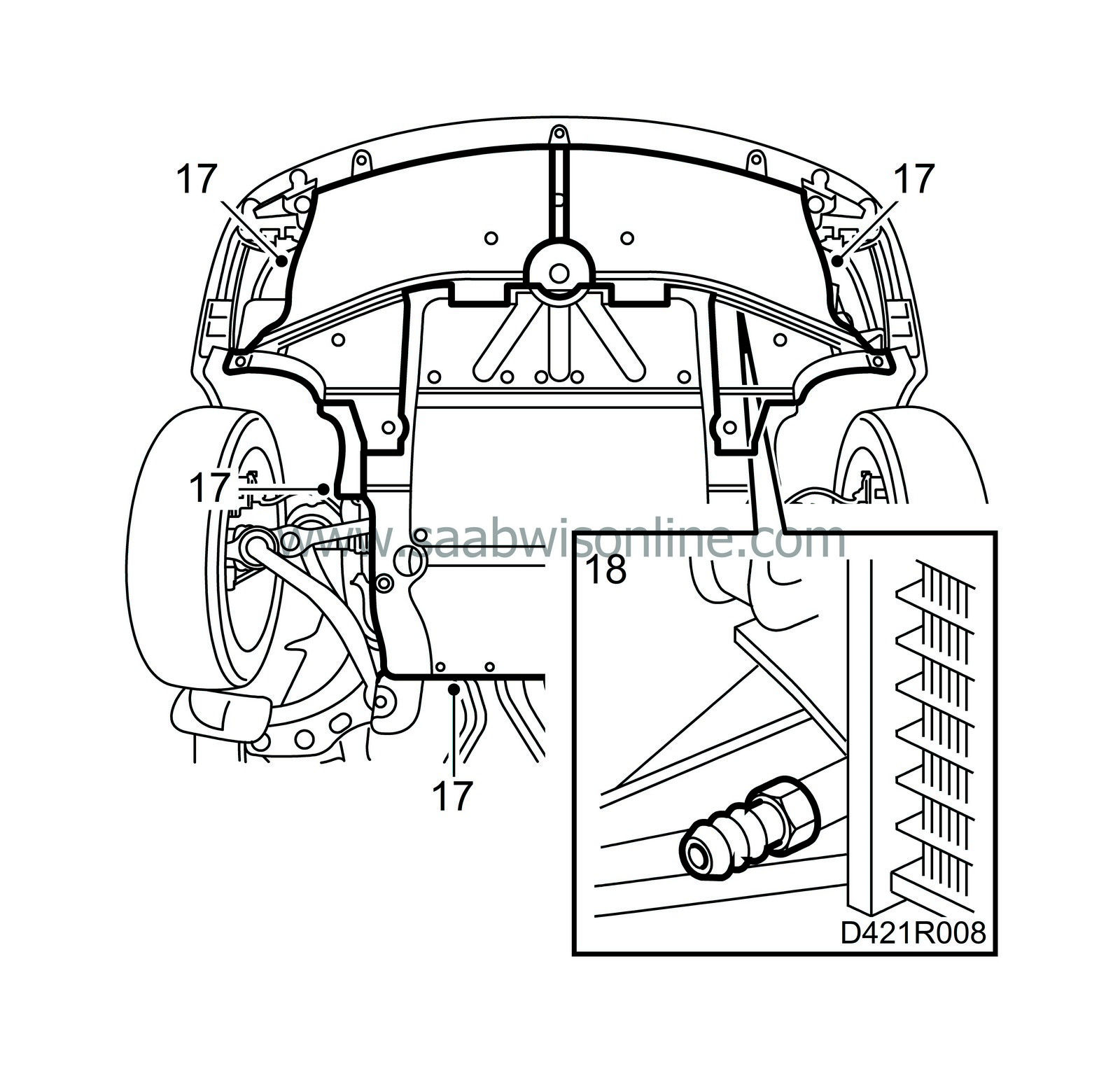
Raise the car and remove the front wheels.
|
|
| 17. |
Remove the lower engine cover, air shields and the cover in the right-hand wheel housing.
|
|
| 18. |
Place a receptacle under the radiator and drain the coolant.
|
|
| 19. |
Relieve the tension on the belt tensioner by turning it anticlockwise (towards the rear of the car) with a 19 mm wrench and lift off the belt.

|
|
| 20. |
Unplug the electrical connection to the A/C compressor (A/C).
|
|
| 21. |
Detach the front exhaust pipe from the turbocharger.

|
|
| 22. |
Undo the joint between the front pipe and the intermediate pipe.
|
|
| 23. |
Take down the front exhaust pipe and remove the auxiliary heater exhaust pipe.
|
|||||||
| 24. |
Remove the hub centre nuts. Detach the brake calipers and suspend them from the suspension strut. Remove the nut on the steering swivel member ball joint on both sides.

|
|
| 25. |
Lower the car and detach the coolant hoses. The thermostat housing vent hose and the hose connected to the generator bracket need only be detached from the engine.

|
|
| 26. |
Pinch the connecting hose on the brake fluid reservoir with hose pinch-off pliers 30 07 739, detach the connecting pipe on the gearbox and seal it.

|
|
| 27. |
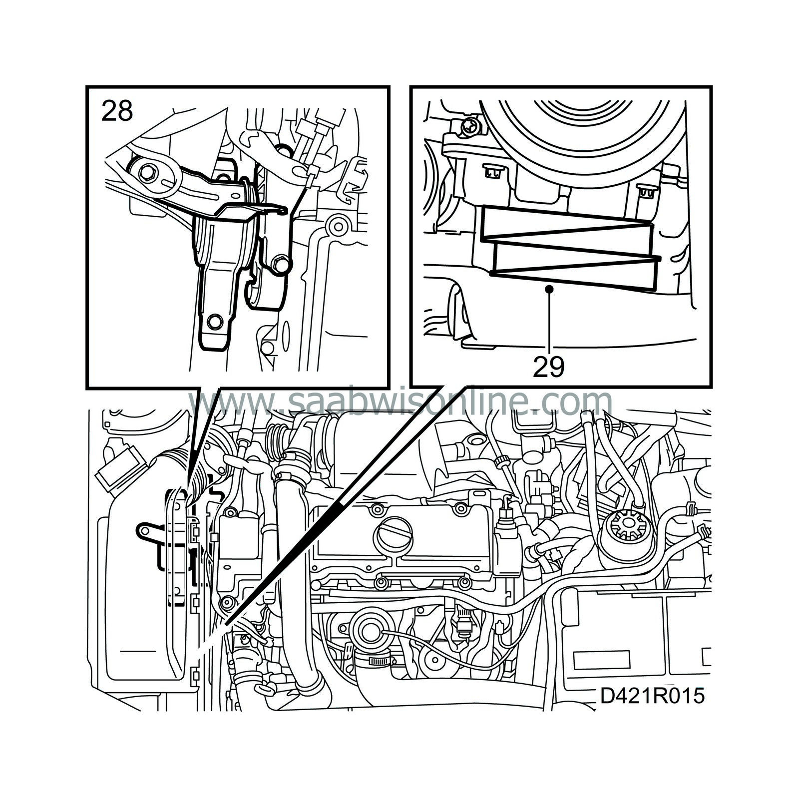
Place a jack with a wooden block on top under the oil sump and carefully lift the engine to take the weight off the right-hand engine mounting.
|
|
| 28. |
Undo the right-hand engine mounting.
|
|
| 29. |
Place wedges between the oil sump and the subframe. Lower the jack and remove it.
|
|
| 30. |
Place a receptacle under the power steering pump, detach the hoses and put them to one side.

|
|
| 32. |
Lower the lifting table with power train and subframe slightly. Undo the steering swivel member ball joint and drive shafts on both sides.
|
|
| 33. |
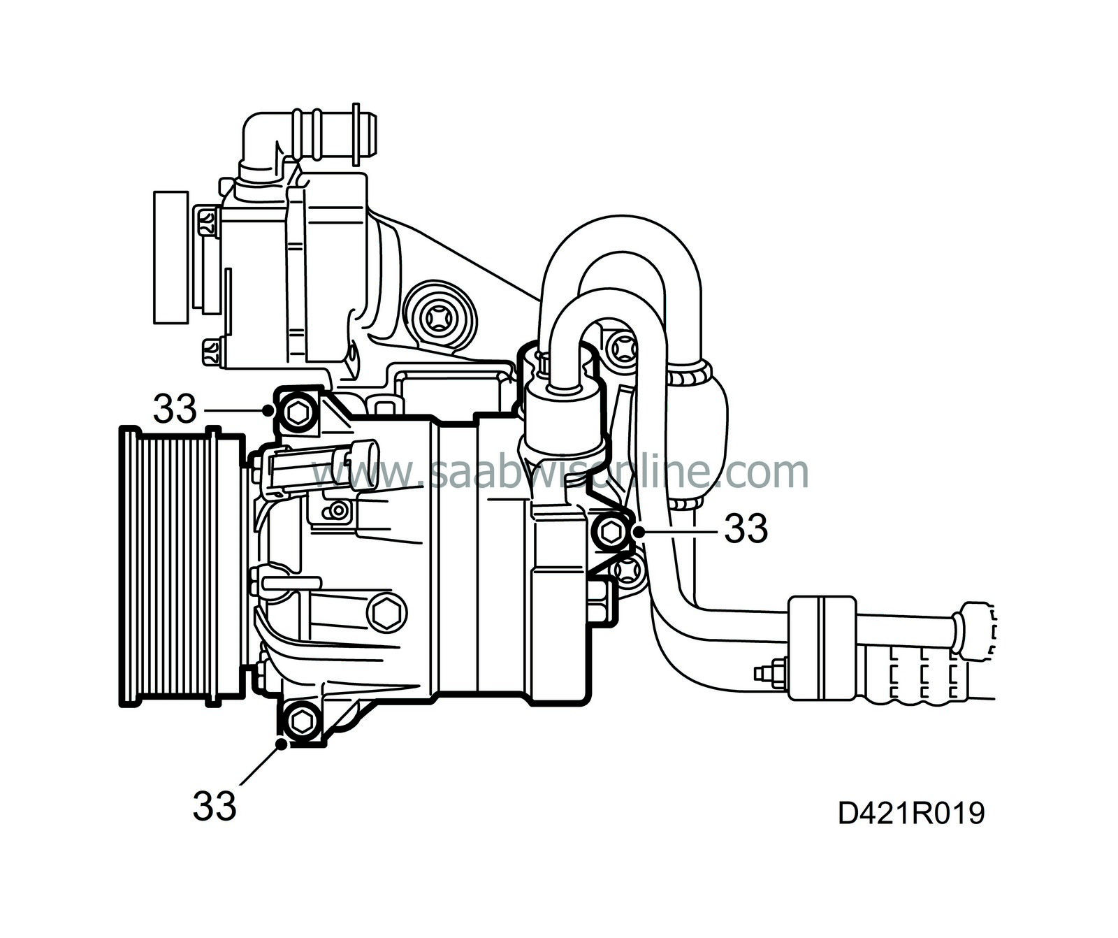
Detach the A/C compressor and suspend it from the lower radiator member with strap 83 95 212.
|
|
| 34. |
Lower the lifting table completely and move it out of the way.
|
|
| 35. |
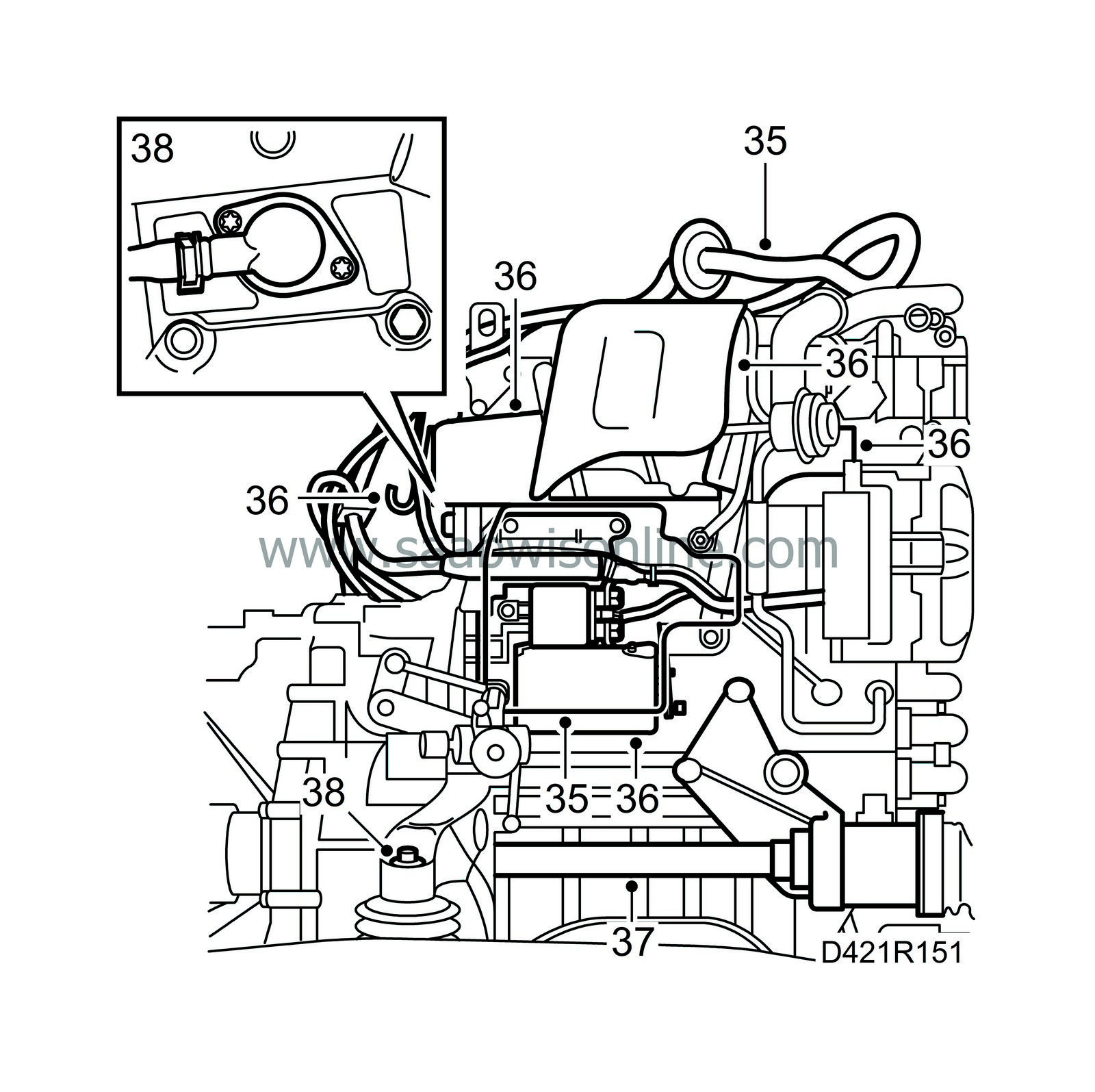
Remove the heat shield from over the starter motor and detach the wiring harness.
|
|
| 36. |
Remove the remaining heat shields and the coolant hose hook and remove the starter motor.
|
|
| 37. |
Remove the right-hand drive shaft with support bearing and fit plug 87 92 244.
|
|
| 38. |
Undo the nut on the rear engine mounting and detach the coolant connection under the vacuum pump.
|
|
| 39. |
Undo all the bolts between the engine and gearbox except the top one.

|
|
| 40. |
Lift the engine with lifting sling 83 92 409 and dismantle the gearbox.
|
|
| 41. |
Fit holder 83 94 751 and place the engine on floor stand 78 74 878.

|
|
| To fit |

|
|||||||||||||
| 1. |
Lift the engine with lifting sling 83 92 409 and fit the gearbox.
Tightening torques Gearbox-cylinder block 70 Nm (52 lbf ft) Gearbox-oil sump 20 Nm (15 lbf ft) (M8) Gearbox-oil sump 40 Nm (30 lbf ft) (M10) |
|
| 2. |
Place the engine and gearbox on the subframe. Place blocks underneath between the engine and the subframe and tighten the nut on the rear engine mounting.
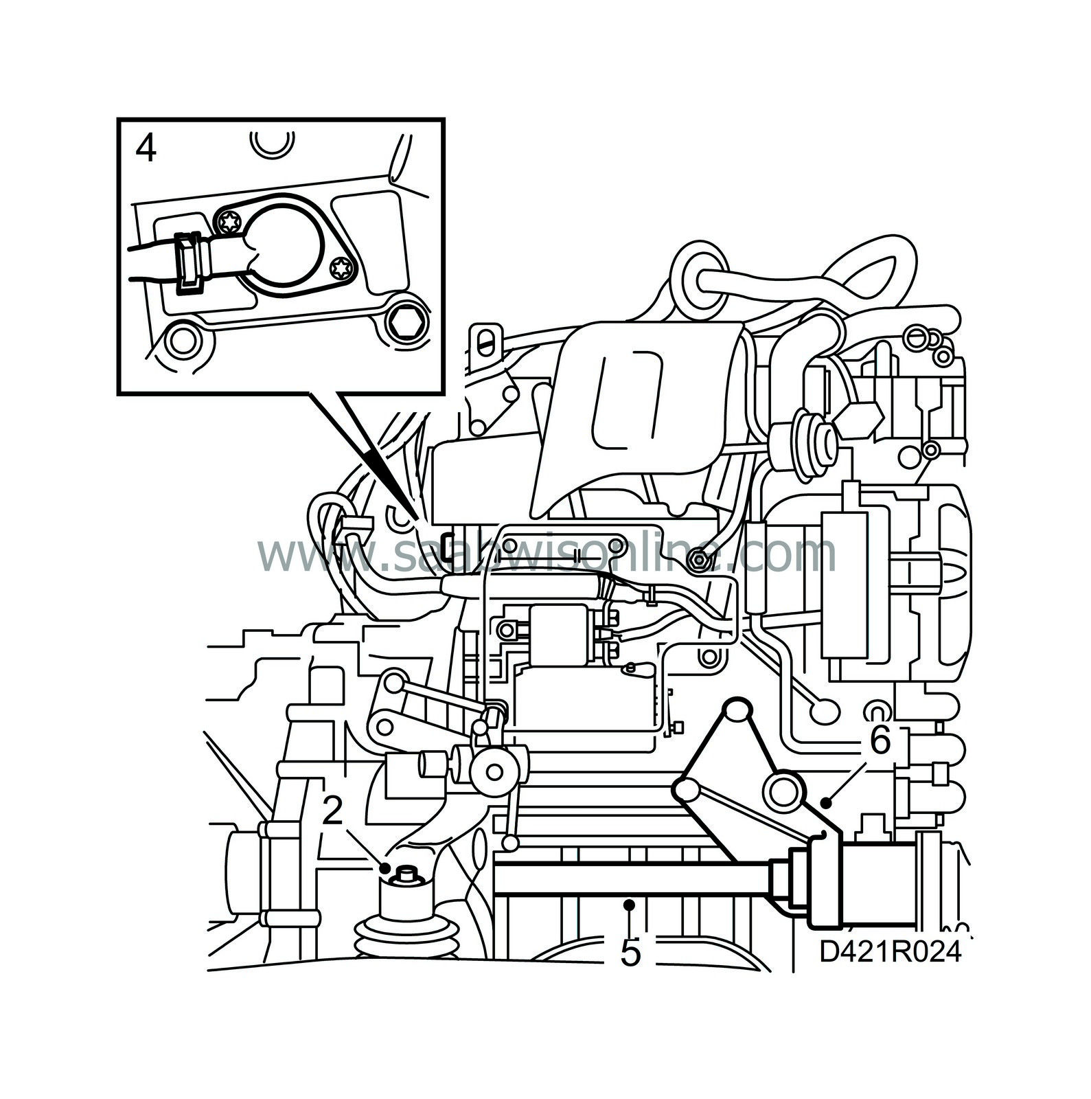
Tightening torque 47 Nm (35 lbf ft). |
|
| 3. |
Remove the lifting sling and engine lift.
|
|
| 4. |
Fit a new O-ring on the coolant connection, lubricate with acid-free vaseline and fit the connection.
|
|
| 5. |
Pull out the plug in the gearbox, fit protective collar 83 95 162, position the drive shaft in the collar and insert it until about 20 mm is remaining. Pull out the tool and fit the drive shaft all the way home.
|
|
| 6. |
Fit the drive shaft support bearing.
Tightening torque 47 Nm (35 lbf ft). |
|
| 7. |
Fit the starter motor and heat shields over the turbocharger and exhaust manifold.

|
|
| 8. |
Put back the coolant hose hook.
|
|
| 9. |
Fit and connect the wiring harness and secure it in the same position as previously.
|
|
| 10. |
Fit the starter motor heat shield.
|
|
| 11. |
Place the lifting table with power train under the raised car.
|
|
| 12. |
Lower the car carefully and raise the lifting table. Position the drive shafts and steering swivel member ball joints.
|
|
| 13. |
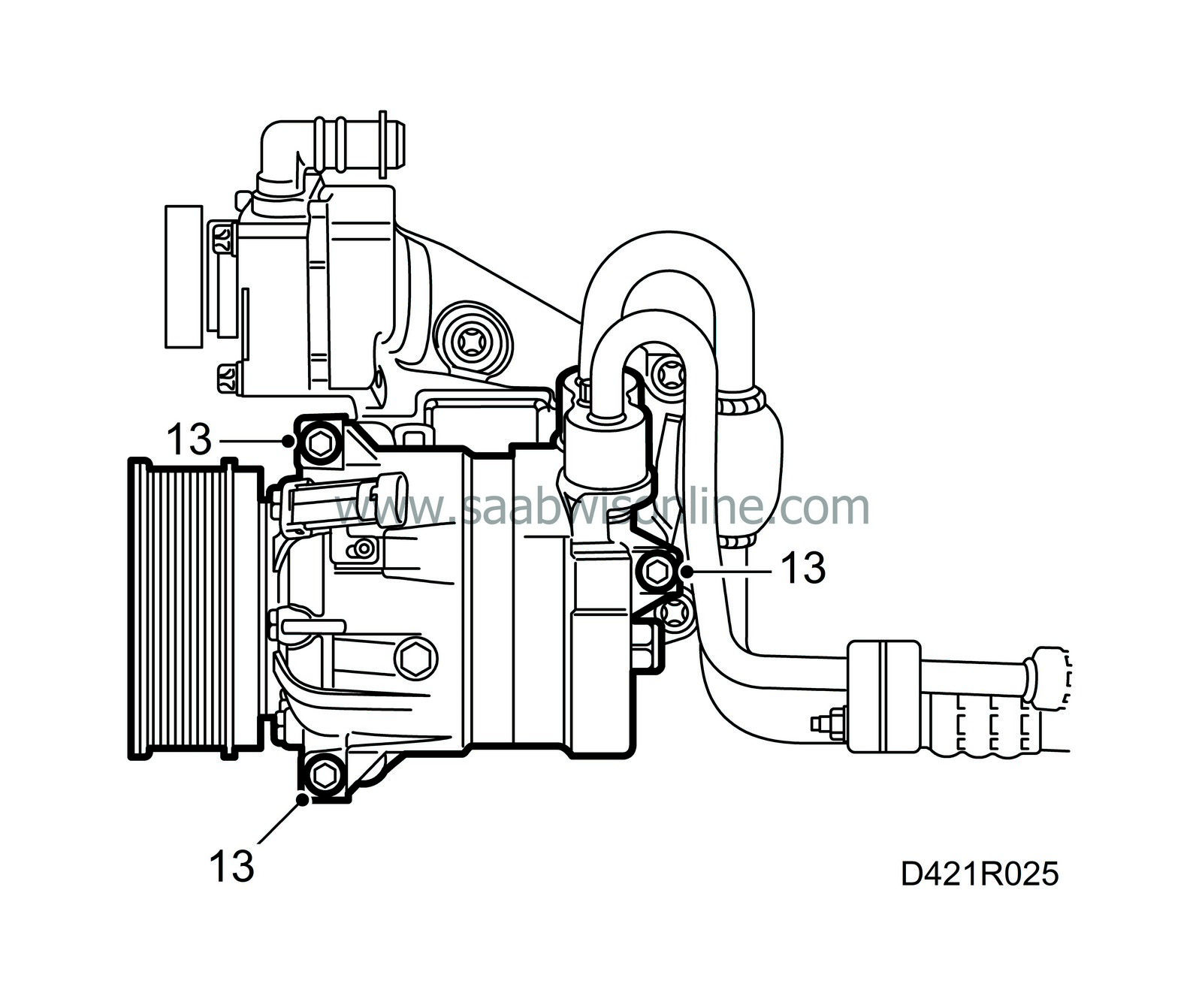
Hang the A/C compressor in place and tighten the bolts.
|
|
| 14. |
Lift the engine and fit the front left engine mounting. Do not tighten the bolts.
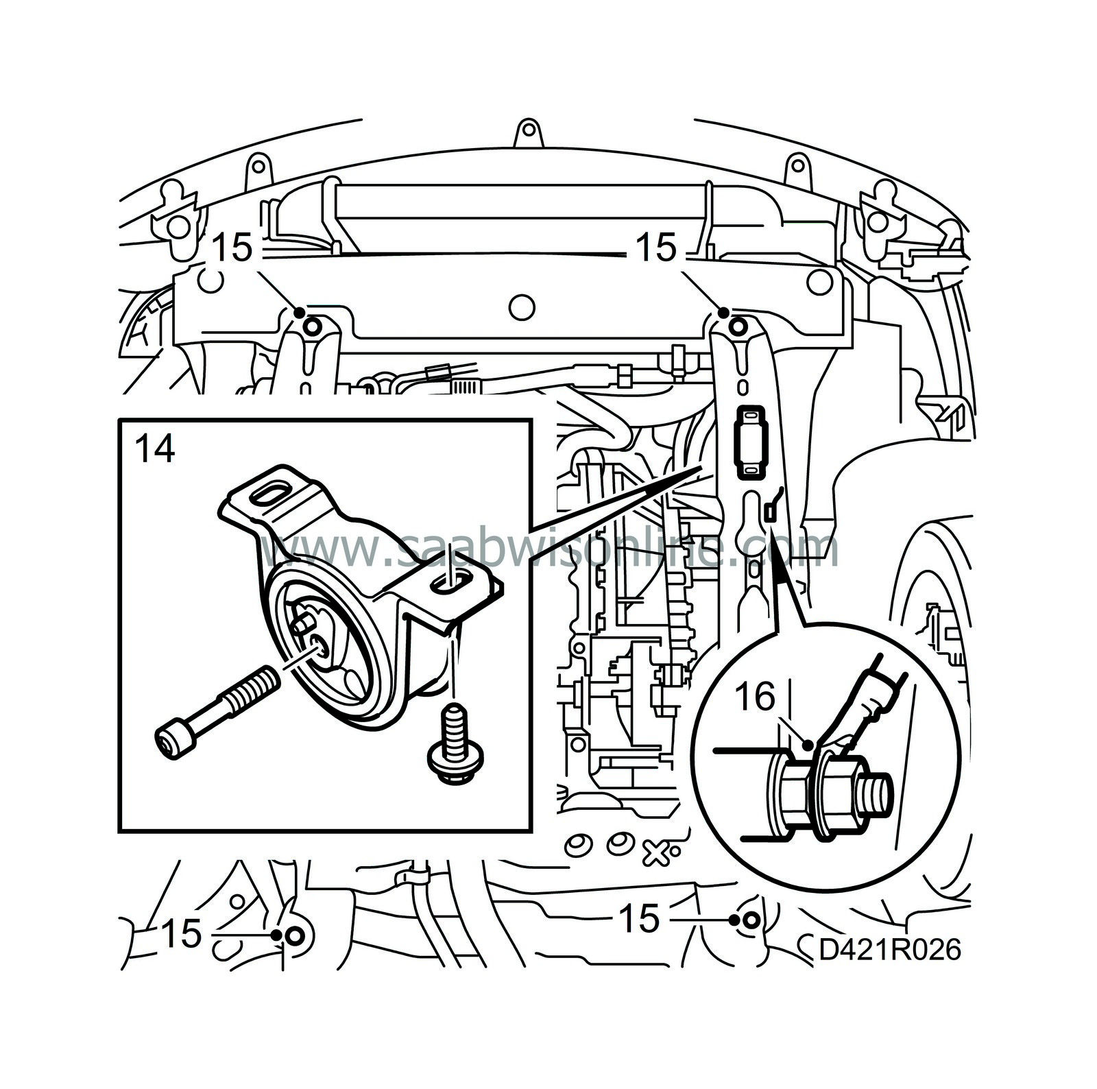
|
|
| 15. |
Tighten the bolts on the subframe.
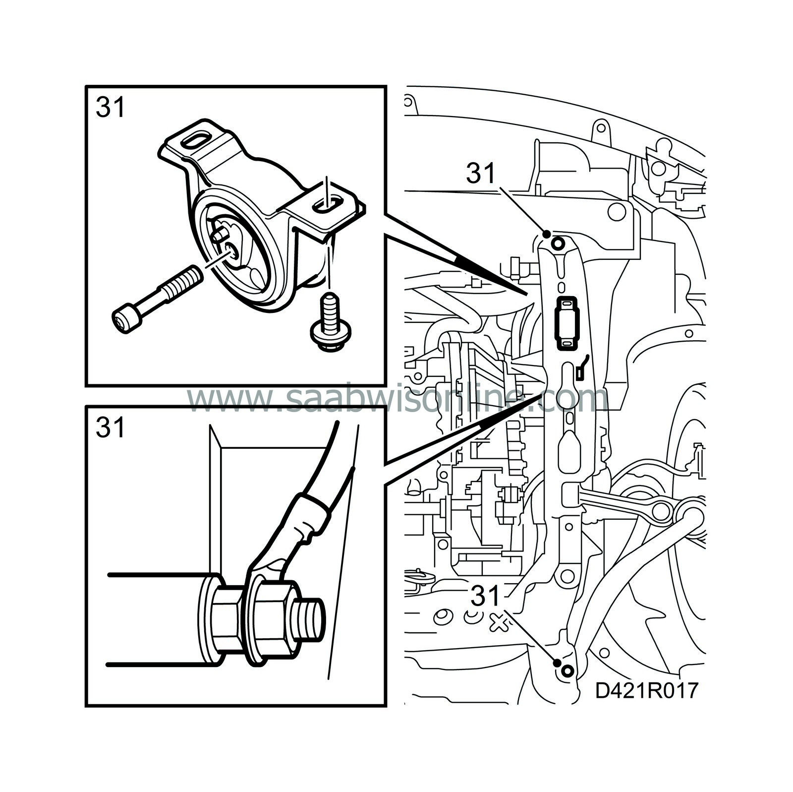
Tightening torques - front: 115 Nm (85 lbf ft) - centre: 190 Nm (140.6 lbf ft) - rear: 110 Nm + 75° (81.4 lbf ft + 75°). |
|
| 16. |
Attach the ground cable to the gearbox.
|
|
| 17. |
Lower the car and attach the hoses to the servo pump with new seals.
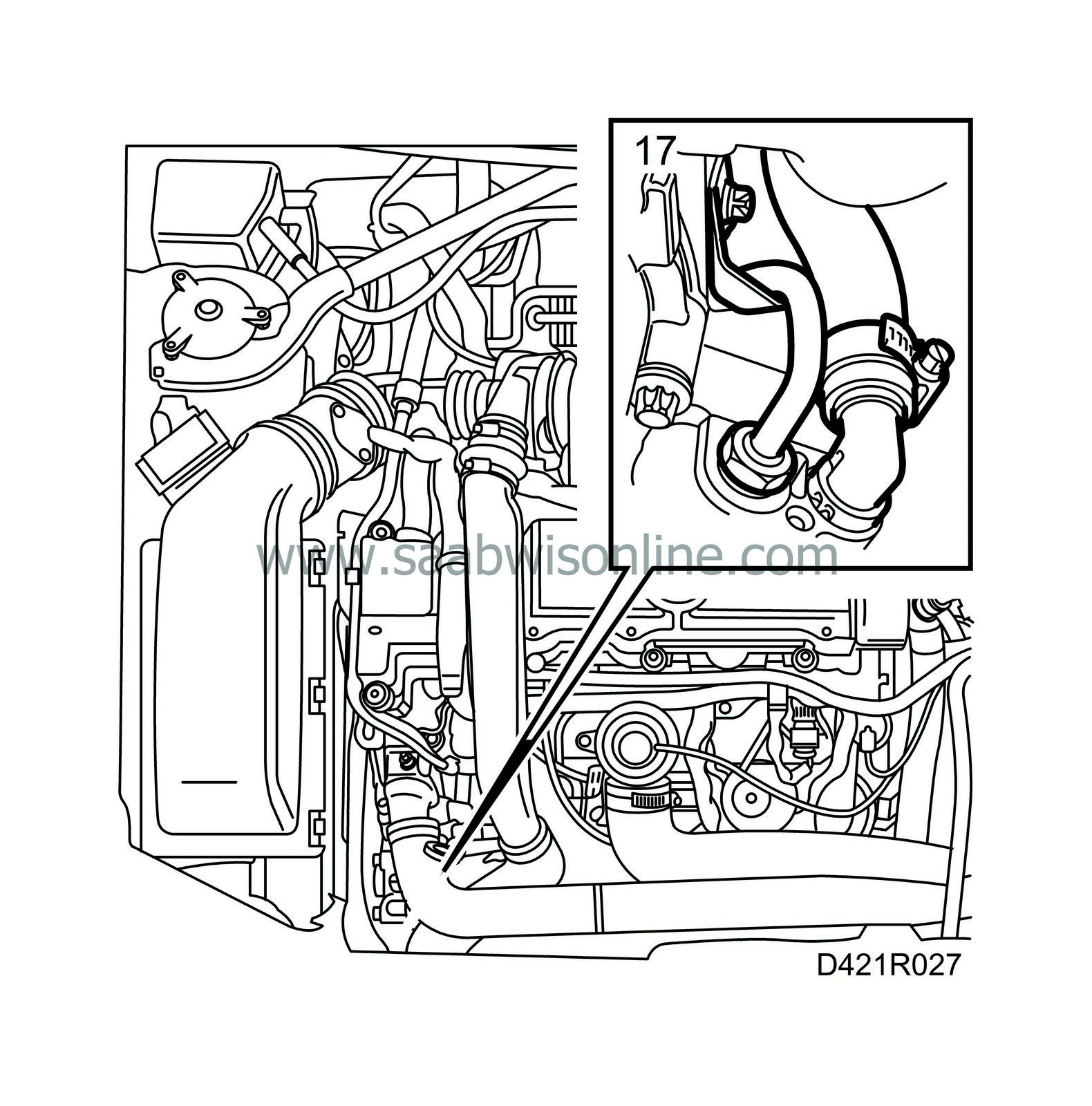
|
|
| 18. |
Place a jack with wood block under the oil sump and carefully raise the engine.
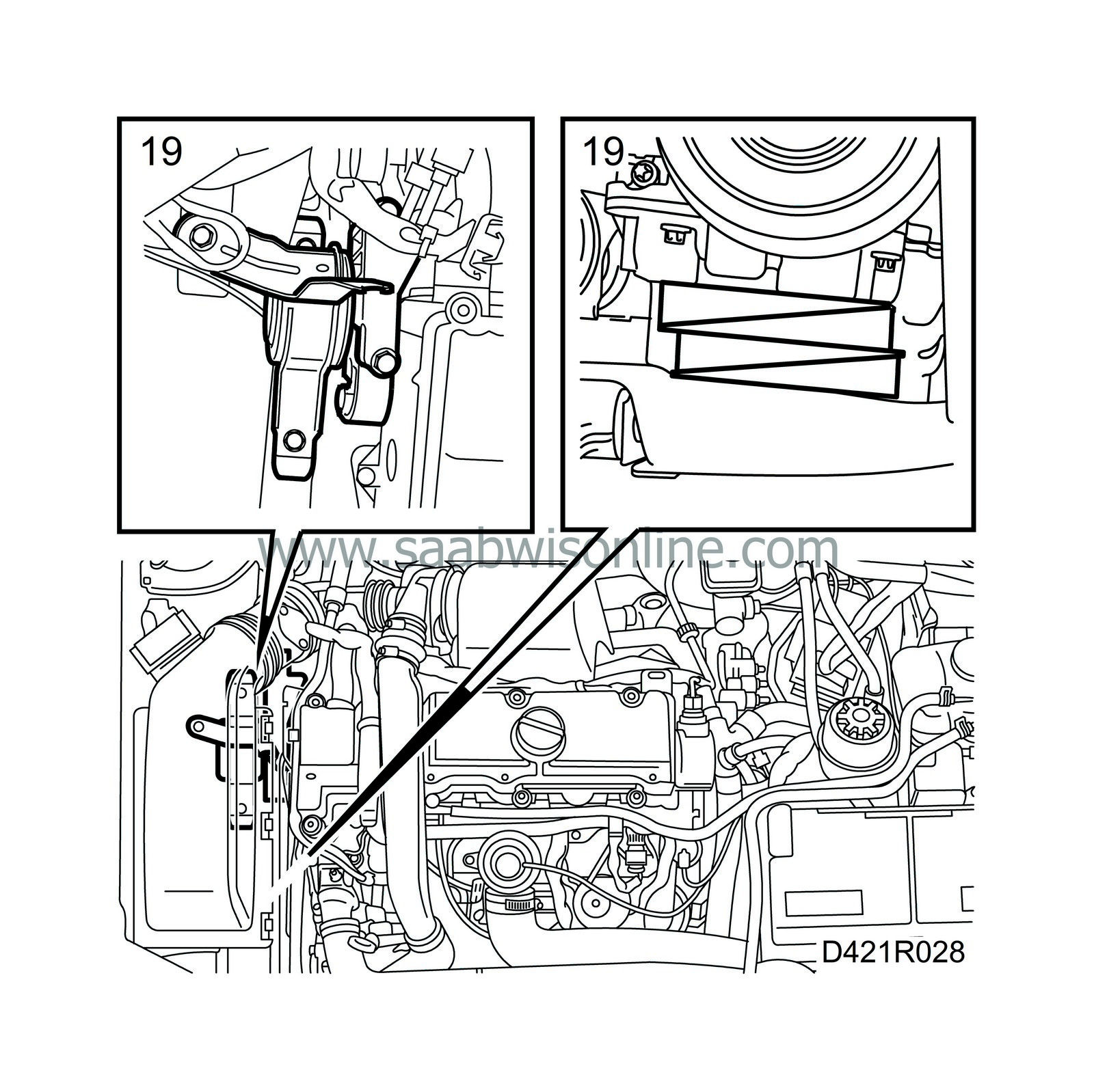
|
|
| 19. |
Fit the right-hand engine mounting.
Tightening torque 47 Nm +45° (35 lbf ft +45°). Remove the wedges and the jack. |
|
| 20. |
Couple the connecting pipe and remove the hose pinch-off pliers.
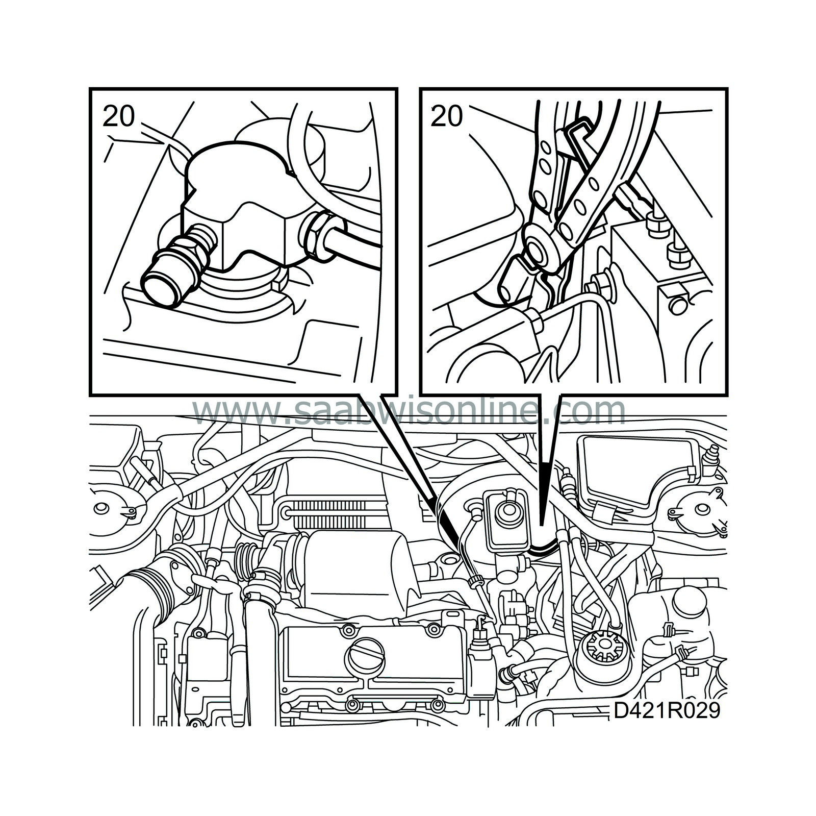
|
|
| 21. |
Connect the coolant hoses.
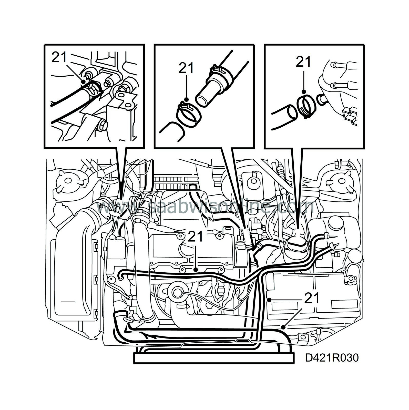
|
|
| 22. |
Apply Molycote 1000 to the turbocharger studs.
|
|
| 23. |
Raise the car and fit the nuts on the steering swivel member ball joints.
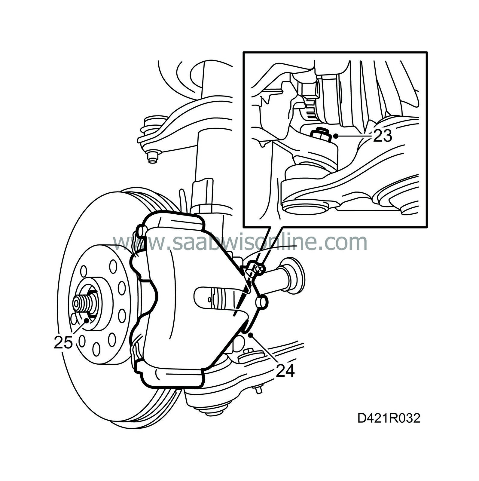
Tightening torque 75 Nm (56 lbf ft) |
|
| 24. |
Refit the brake calipers. Apply threadlock 74 96 268 to the bolts before fitting.
Tightening torque 105 Nm (78 lbf ft) |
|
| 25. |
Screw on new hub centre nuts loosely and refit the wheels.
Tightening torque, wheel 110 Nm (81 lbf ft) |
|
| 26. |
Tighten the bolts on the left-hand engine mounting.
Tightening torque 62 Nm (46 lbf ft) |
|
| 27. |
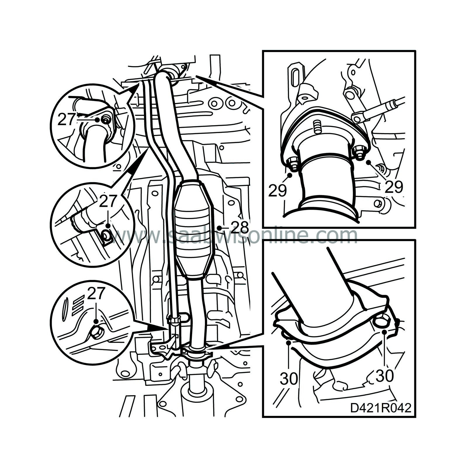
Clean the joint on the exhaust pipe and refit the auxiliary heater exhaust pipe.
|
|
| 28. |
Position the front part of the exhaust pipe with a new gasket and fit new nuts.
|
|
| 29. |
Fit the front exhaust pipe loosely, making sure it is not strained, and tighten it to the turbocharger.
Tightening torque 25 Nm (18 lbf ft) |
|
| 30. |
Tighten the front exhaust pipe to the intermediate pipe.
Tightening torque 30 Nm (22 lbf ft) |
|
| 31. |
Reconnect the A/C compressor.

|
|
| 32. |
Fit the multigroove V-belt on all the pulleys. Relieve the tension on the belt tensioner by turning it anticlockwise (towards the rear of the car) with a 19 mm wrench and fit the belt on its pulley. Make sure the belt is positioned correctly on all the pulleys.
|
|
| 33. |
Make sure the radiator and engine oil drain plugs are tight.
|
|
| 34. |
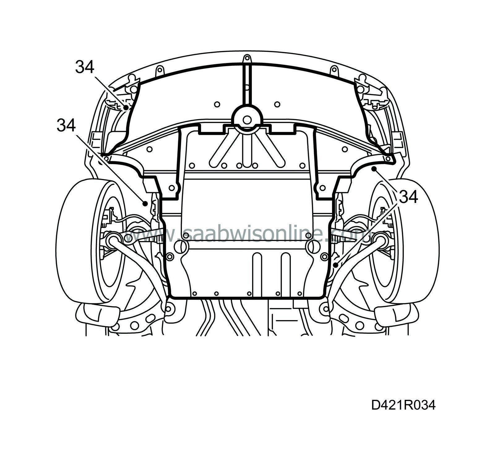
Fit the air shields, the cover in the right-hand wheel housing and the lower engine cover.
|
|
| 35. |
Lower the car and tighten the hub centre nuts. Use new nuts.
Tightening torque 230 Nm (170 lbf ft) Tightening torque, nuts with top groove: 170 +45°Nm (125 lbf ft + 45°)
|
|||||||||
| 36. |
Tighten the remaining nuts between the turbocharger and the front exhaust pipe.

Tightening torque 25 Nm (18.5 lbf ft). |
|
| 37. |
Connect the vacuum hose to the control valve diaphragm box.
|
|
| 38. |
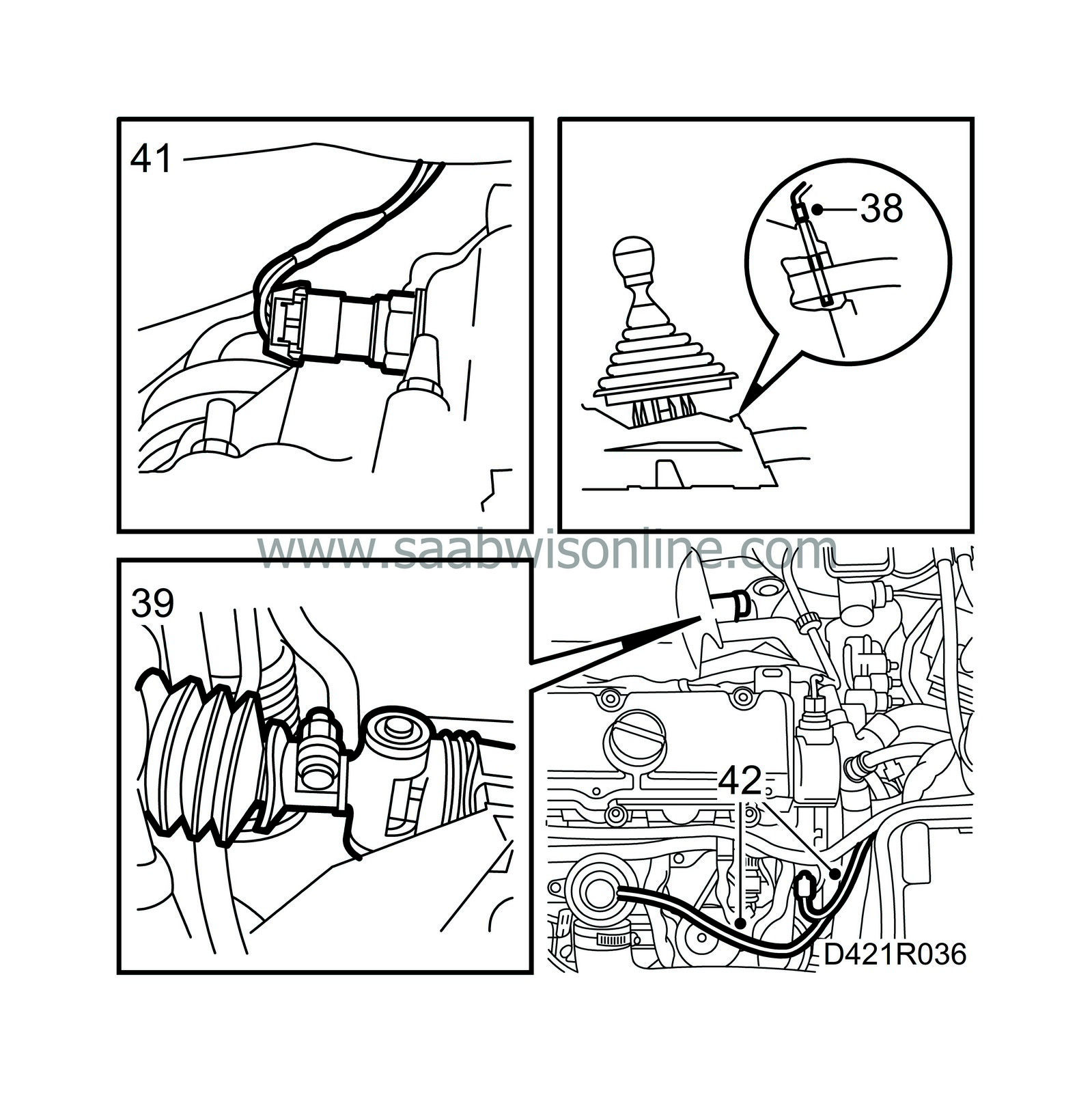
Lift up the gear lever boot, move the lever to 4th gear and insert locking pin 87 92 335 into the gear lever housing.
|
|
| 39. |
Tighten the clamp on the gear linkage on the gearbox.
Tightening torque 21 Nm (15.5 lbf ft). |
|
| 40. |
Put back the plug in the gearbox and fit the gear lever boot.
|
|
| 41. |
Plug in the reversing light connector.
|
|
| 42. |
Attach the vacuum hoses to the EGR valve and swirl throttle.
|
|
| 44. |
Refit the hoses to the charge air cooler and intake manifold.

|
|
| 45. |
Fit the turbocharger delivery pipe.
|
|
| 46. |
Connect the vacuum hoses to the vacuum pump.
|
|
| 47. |
Insert the wiring harness through the bulkhead. Check the seal. Plug in the cable on the bulkhead.
|
|
| 48. |
Fit and connect the accelerator pedal position sensor.
|
|
| 49. |
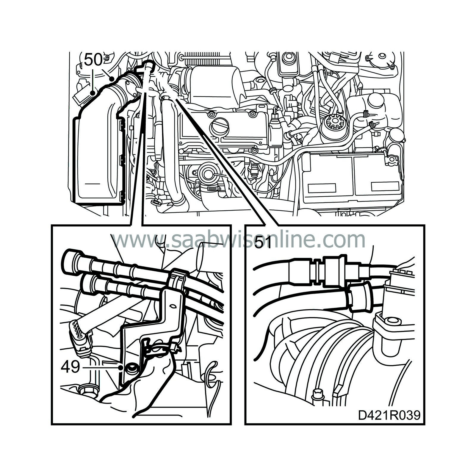
Fit the wiring harness bracket and press the fuel lines onto it. Secure the wiring harness as marked.
|
||||||||||
| 50. |
Fit the air cleaner with mass air flow sensor and hoses, and plug in the mass air flow sensor.
|
|
| 51. |
Connect the fuel hoses.
|
|
| 52. |
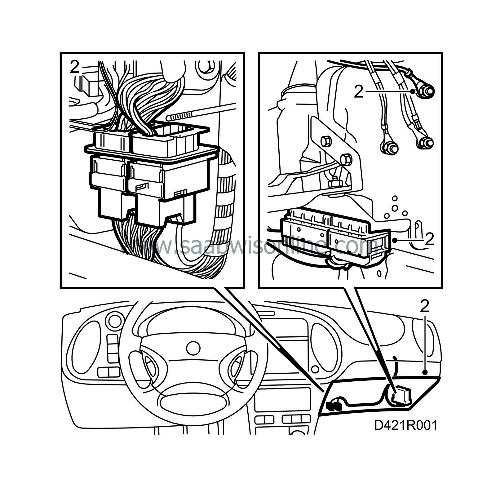
Connect the wiring harness to the control module and grounding point under the dashboard, refit the control module, refit the glove box or lower dashboard panel and put back the floor mat. Make sure the rubber grommet in the bulkhead is fitted correctly.

|
|
| 53. |
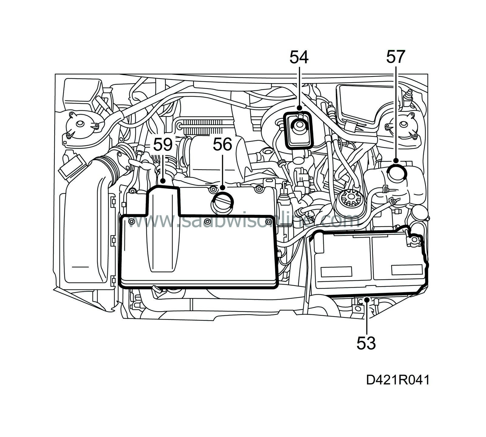
Fit the battery and connect the battery cables.
|
|
| 54. |
Top up with brake fluid in the brake fluid reservoir if necessary and undo the bleed nipple on the slave cylinder. Connect bleeder tool 88 19 096 to the bleed nipple and compressed air to the bleeder tool. Bleed the clutch until clear fluid appears from the nipple.
|
|
| 55. |
Tighten the bleed nipple and remove the bleeder tool. Check the operation of the clutch and top up with brake fluid to the correct level. Replace the cap.
|
|
| 56. |
Fill with engine oil as specified in

|
|
| 57. |
Fill with coolant, check the integrity of the system and bleed it as follows:
Connect exhaust hoses to both the engine exhaust system and the auxiliary heater exhaust system and start the engine. Start the parking heater with the diagnostic tool (Body, SID, Activate, Heater). The parking heater stops when the engine temperature has reached 80°C or if the parking heater menu is exited. Make sure there is a continuous flow of coolant in the hose from the thermostat housing to the expansion tank. Run the engine until the thermostat has opened. |
|||||||
| 58. |
Check the coolant and oil levels (power steering fluid also), top up as necessary.
|
|
| 59. |
Fit the cover, remove the wing covers and check cleanliness in the engine bay.
|
|
| 60. |
Adjust the clock in the car and press 5 times on the remote control lock/unlock button.
|
|
| 61. |
Start the engine and check all functions. Road test the car.
|
|

 Warning
