Valve stem seals
| Valve stem seals |
(in-car)
| To remove |
(This method can also be used when changing valve springs, valve discs or tappets.)
|
||||||||||||||||||||||
| 1. |
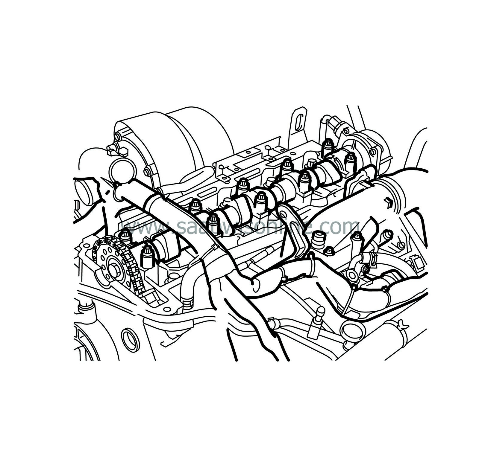
Remove the
Camshaft
|
|
| 2. |
Vacuum up any oil on top of the cylinder head.
|
|
| 3. |
Detach the air hose from the intake manifold, bend it to one side and seal it.
|
|
| 4. |
Bend aside the wiring harness duct.
|
|
| 5. |
Unplug the EGR valve.
|
|
| 6. |
Remove the throttle body.
|
|
| 7. |
Remove the bolts securing the EGR valve and move the valve to one side.
|
|
| 8. |
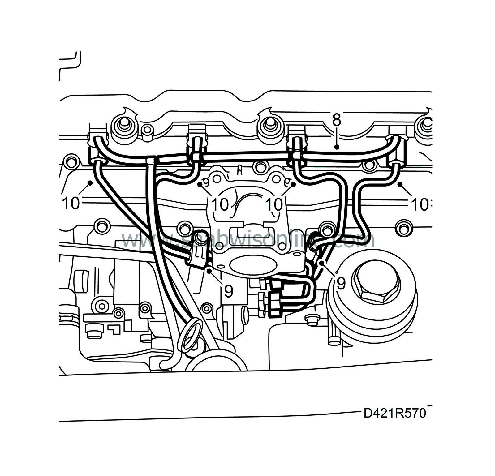
Remove the fuel return hoses.
|
|
| 9. |
Note the position of the fuel rails and their clamps, and mark the rails.
|
|
| 10. |
Remove the fuel rails (the clamps can be removed if necessary).
|
|
| 11. |
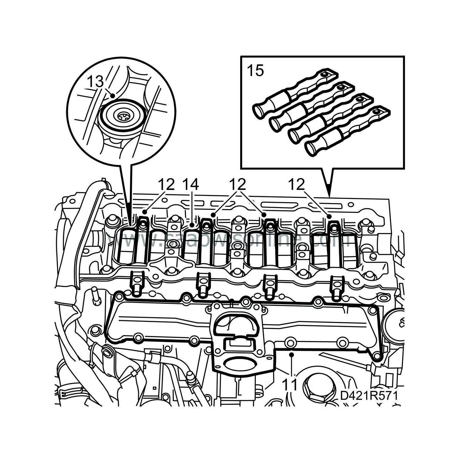
Remove the upper part of the intake manifold and seal the passageways.
|
|
| 12. |
Remove the retaining screws for the fuel bridges, lift the fuel bridges and pull them out of the cylinder head.
|
|
| 13. |
Remove the valve bridges.
|
|
| 14. |
Remove the seals on the injector connections in the cylinder head.
|
|
| 15. |
Fit
Fixing tool, injectors
over the injectors
|
|
| 16. |
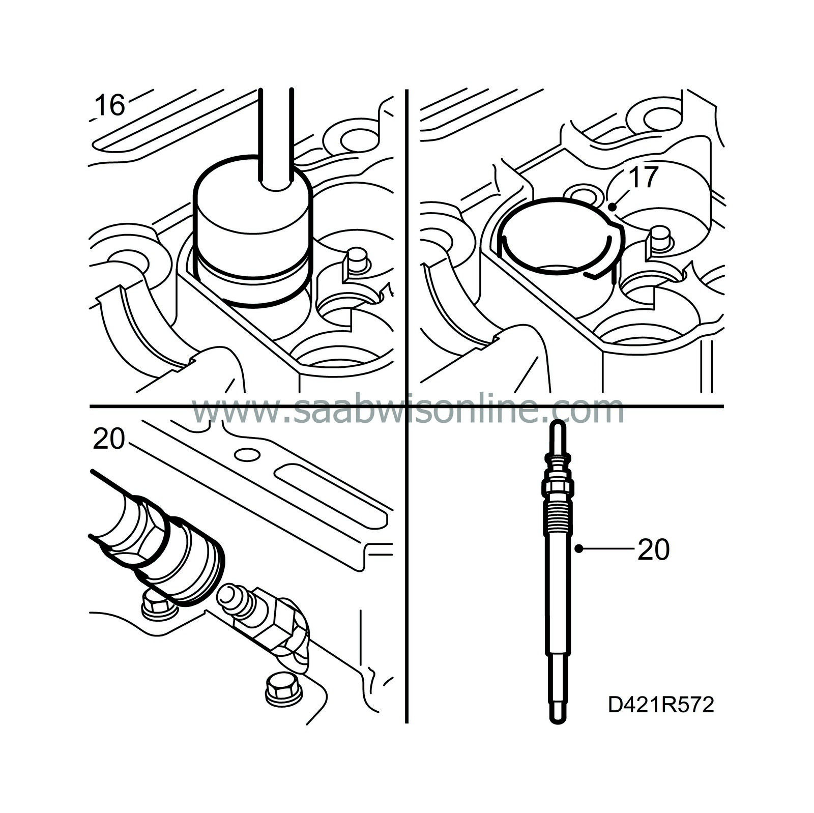
Lift up the valve tappets with
83 91 401 Magnetic tool
.
|
|
| 17. |
Fit
83 95 022 Protective collars
around the valve springs to protect the sealing surfaces of the tappets. Note the position of the collars.
|
|
| 18. |
Rotate the crankshaft so that the piston in the relevant cylinder is at top dead centre.
|
|
| 19. |
Engage 1st gear and apply the handbrake.
|
|
| 20. |
Unscrew the glow plug from the cylinder in question and fit
Adapter, compression test, diesel
83 95 345 and
Air nipple
83 95 501.
Connect the compressed air and carefully pressurize the piston and valves. 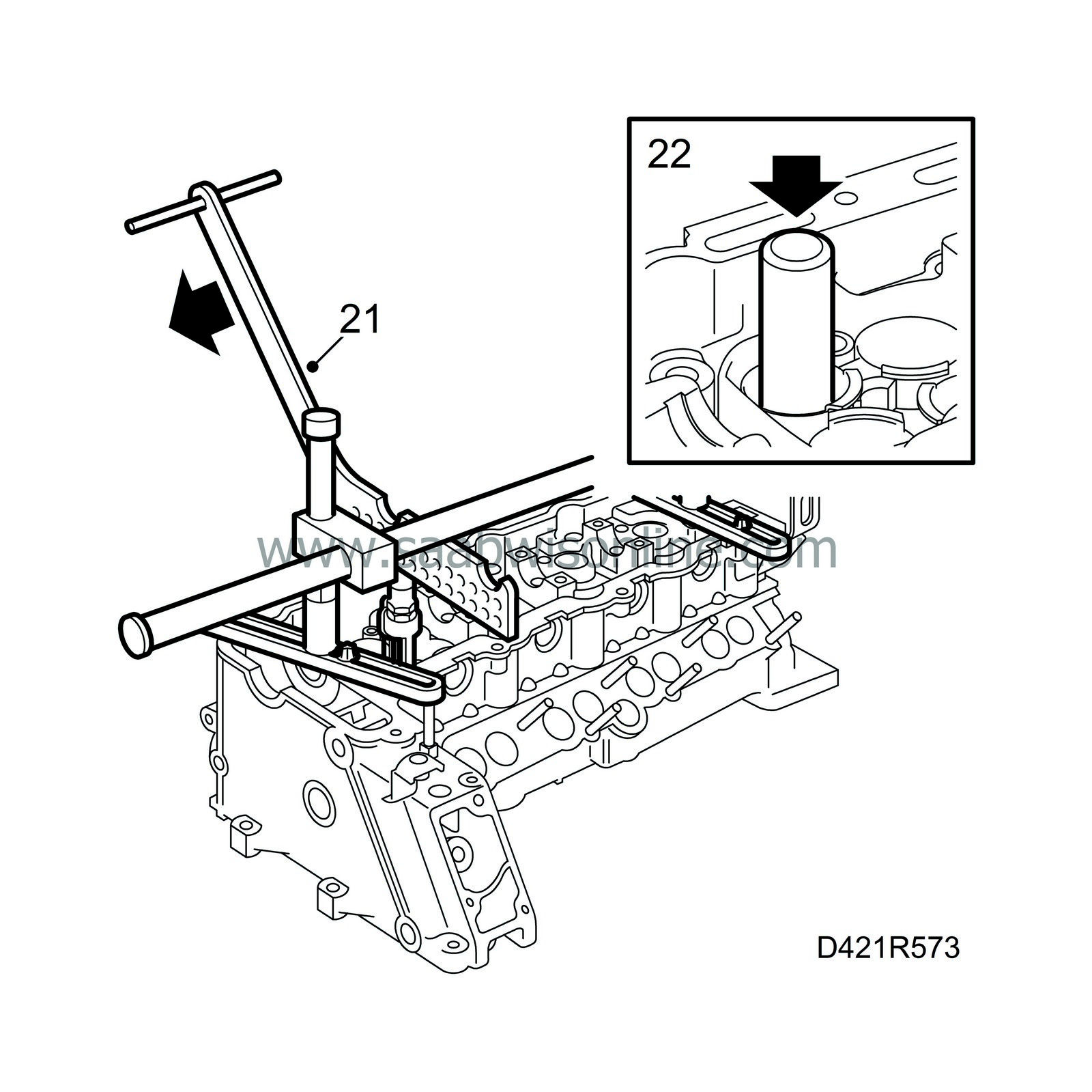
|
|||||||||
| 21. |
Fit
83 95 246 Valve spring depressor
onto the cylinder head. Press down the lever and remove the valve cones.
|
|
| 22. |
Lift out the spring disc and valve spring. Remove the valve guide seal with
83 94 157 Pliers, valve guide seal
.
|
|
| To fit |
(This method can also be used when changing valve springs, valve discs or tappets.)
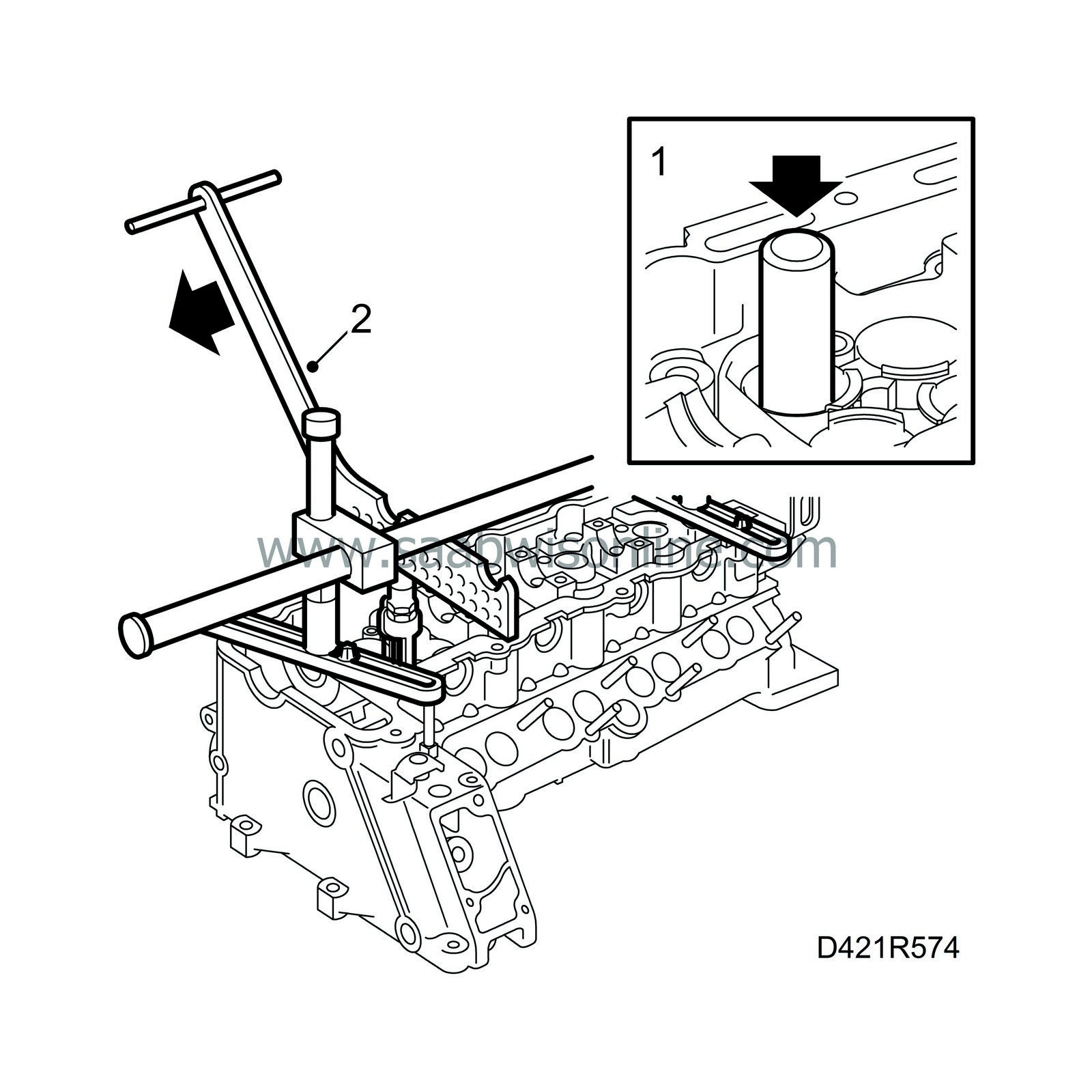
| 1. |
Remove the stem from
83 95 071 Fitting tool, valve stem seal
and place the valve guide seal in the tool with the rubber flange facing inward (upward on the valve stem). Fit the seal to the valve. Using plastic mallet, gently tap the seal into position.
|
|
| 2. |
Fit the spring and spring disc, and place the valve cones in the groove on the spring disc. Press down the lever on the valve compressor and position the valve cones. Remove the valve compressor.
|
|
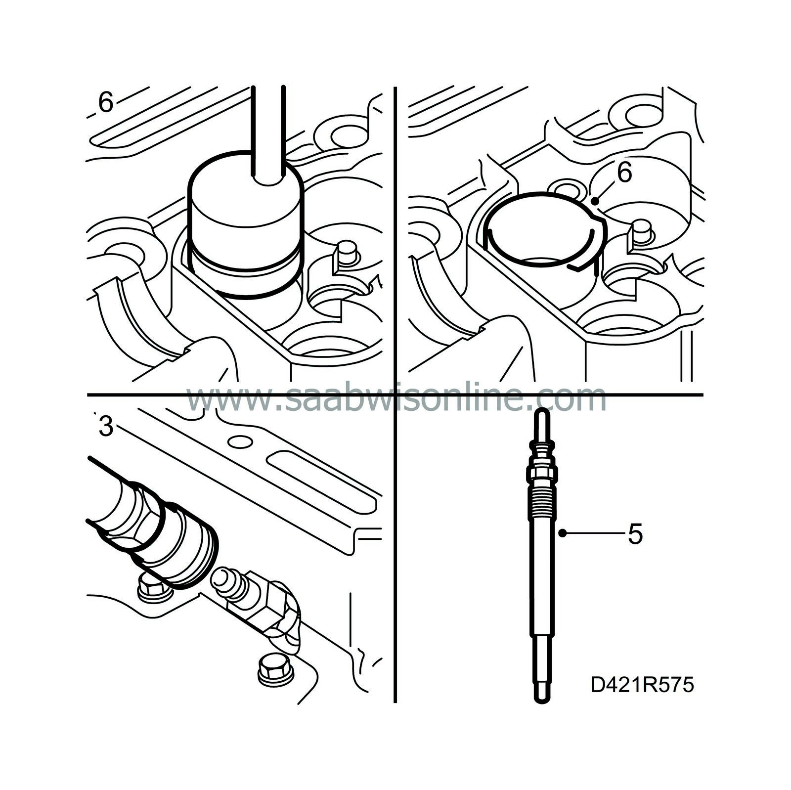
| 3. |
Disconnect the compressed air and remove the air nipple.
|
|
| 4. |
Rotate the crankshaft to the 0-mark.
|
|
| 5. |
Fit the glow plugs.
Tightening torque 10 Nm (8 lbf ft). |
|
| 6. |
Remove the protective sleeves and fit the valve tappets.
|
|
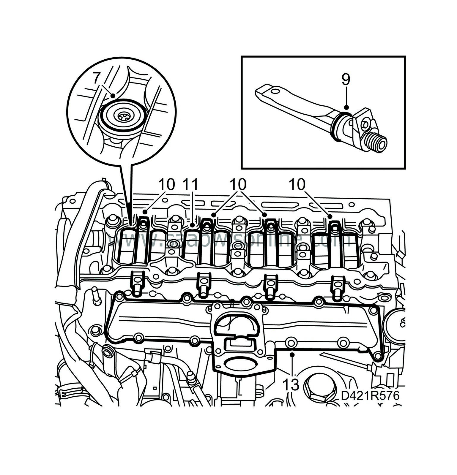
| 7. |
Remove the fixing tools and fit new seals on the injector connections in the cylinder head. Remove any remains of old seals.
|
|
| 8. |
Blow the holes for the fuel bridge retaining bolts clean.
|
|
| 9. |
Fit new O-rings on the fuel bridges, lubricate the O-rings with acid-free vaseline and slide the fuel bridges into the cylinder head.
|
|
| 10. |
Tighten the fuel bridge retaining bolts by hand using a socket and extension piece. Then use a ratchet handle to tighten them a further 360°.
|
|
| 11. |
Fit the valve bridges.
|
|
| 12. |
Clean the sealing surfaces.
|
|
| 13. |
Fit a new gasket on the lower part of the intake manifold and fit the upper part.
Tightening torque 10 Nm (7 lbf ft). |
|
| 14. |
Check the fuel rail connecting cones and replace if necessary.
|
|
| 15. |
Attach the fuel rails with clamps in their original positions.
Tightening torque 25 Nm (19 lbf ft) 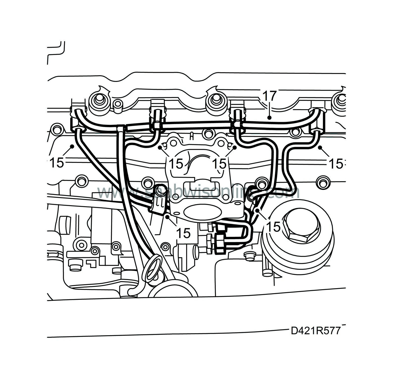
|
|
| 16. |
Check the condition of the fuel return hoses and joints and replace if necessary.
|
|
| 17. |
Connect the fuel return hoses to the fuel bridges. Detach the fuel return hose from the fuel pump and connect the hose to
30 14 883 Pressure/vacuum pump
. Create a vacuum of 750 mbar and wait 1 minute. Check that the pointer on the tool has not moved.
If there is found to be a leak, the fuel bridges must be examined individually. Connect the pressure/vacuum pump to the return fuel connection (not to the return hose) on each fuel bridge. If the fuel bridges are OK, check the return fuel hoses and T-pieces. The hoses should be pliable and exhibit no cracks or other damage. If there are signs of leakage, change all fuel return hoses and T-pieces. If a fuel bridges leaks, remove it, change the seal and refit the bridge. Check for leakage once again. |
|
| 18. |
Fit the EGR valve and the throttle body.
Tightening torque, throttle body: 10 Nm (7 lbf ft) 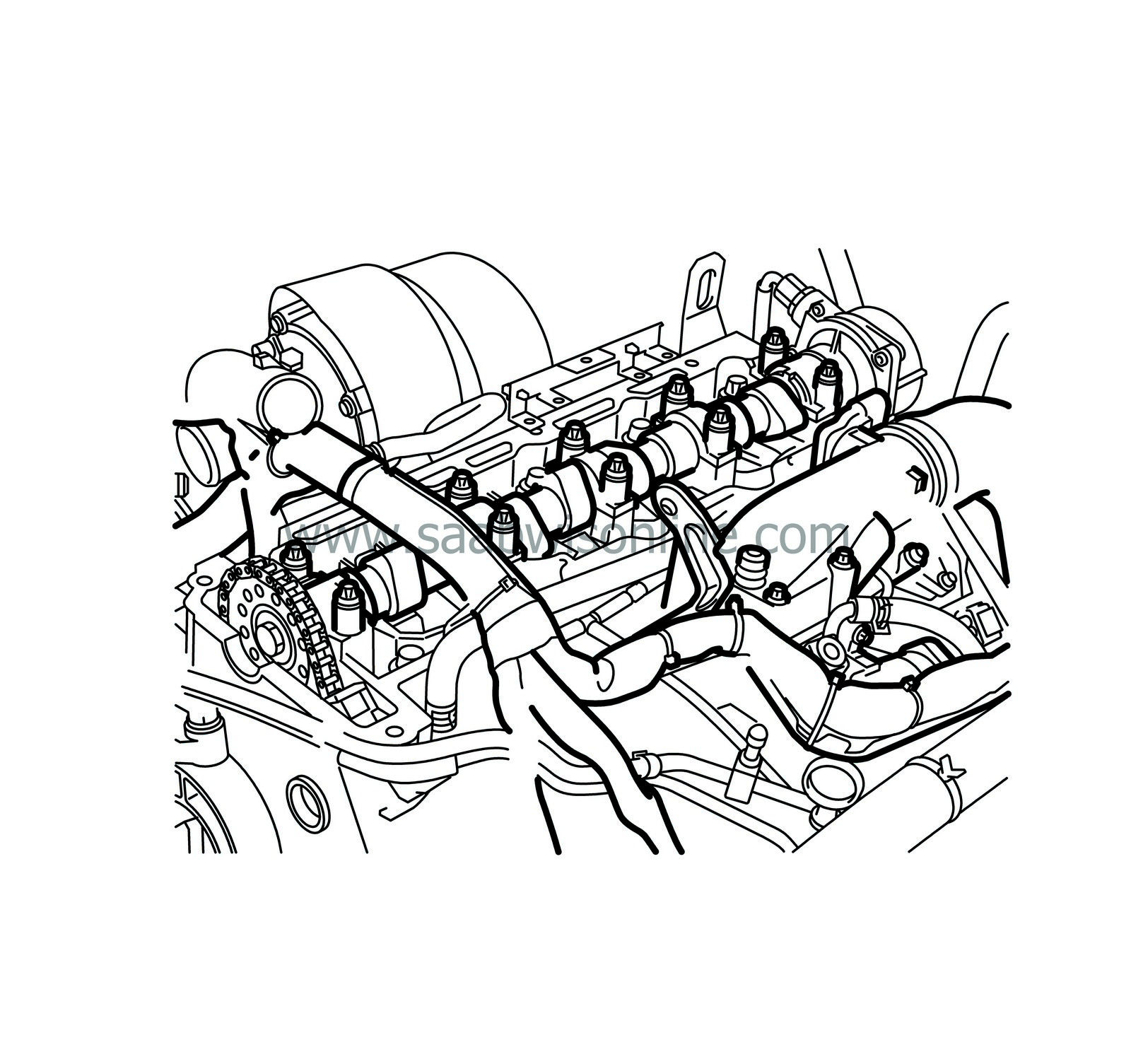
|
|
| 19. |
Fit the wiring harness duct to the engine. Plug in the EGR valve.
|
|
| 20. |
Secure the wiring harness as it was previously.
|
|
| 21. |
Refit the hose on the intake manifold.
|
|
| 22. |
Fit the camshaft, refer to
Camshaft, VIN 12020001-
|
|

 Warning

