Fitting pistons (in situ)
|
|
Fitting pistons (in situ)
|
(Cylinder head removed)
|
Important
|
|
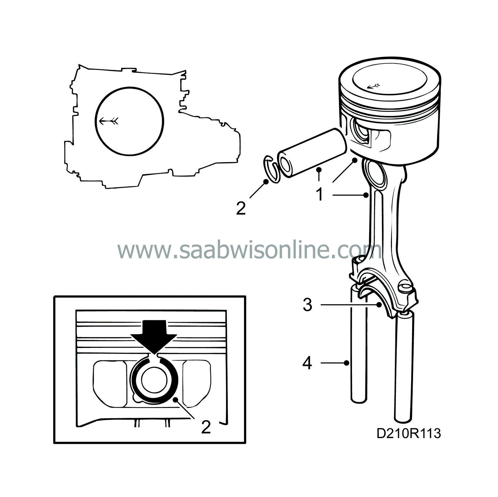
Pistons of different makes must not be used in the same engine. The name of the manufacturer is cast inside the piston.
|
|
|
|
1.
|
Assemble piston and connecting rod by driving in the gudgeon pin, using a plastic mallet and drift. Make sure that the mark on the piston crown faces the timing cover and that the numbers on the connecting rods face the exhaust side.
|
Important
|
|
If one connecting rod is to be changed to a newer type (part no. 91 97 617), all the connecting rods must be changed or the difference in weight will become too great.
|
|
|
|
|
2.
|
Fit the gudgeon pin lock ring.
 Warning
|
|
It is extremely important to fit the lock ring with its opening upwards.
|
|
|
|
|
|
|
|
3.
|
Place the bearing halves in place in the connecting rods.
|
|
4.
|
Fit protective sleeves, part no. 75 19 531, on the connecting rod studs and oil the piston rings, bearings and cylinder.
|
|
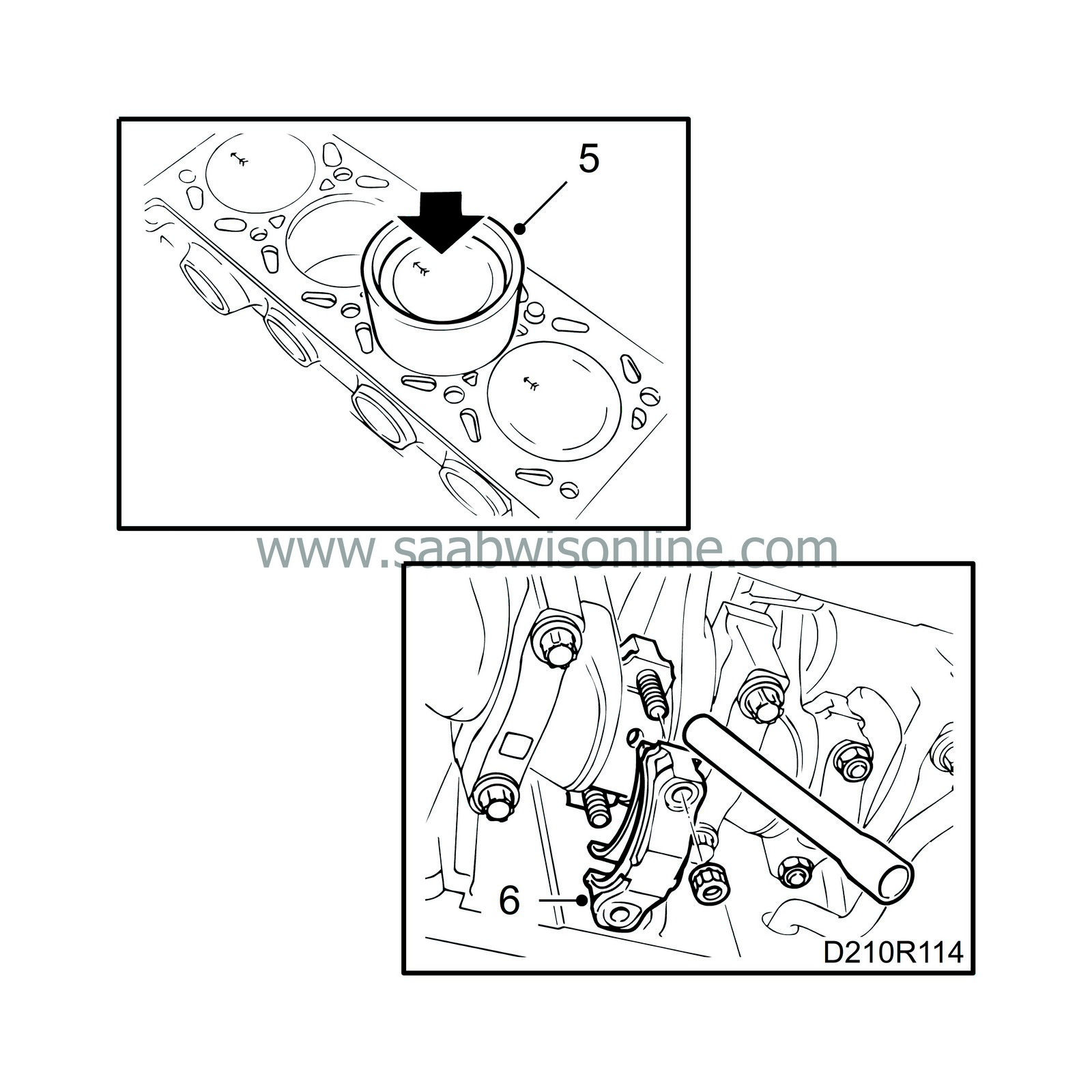
5.
|
Fit the piston using the fitting tool, part no. 78 62 287.
|
|
6.
|
Fit the big-end bearing caps with bearing halves (connecting rod numbers facing in the same direction).
Tightening torques:
20 Nm + 70˚ (14.8 lbf ft + 70˚)
|
|
7.
|
Check that there are no impurities or other foreign matter in the sump and clean the sealing surfaces with benzine.

|
|
8.
|
Apply an even bead of flange sealant, part no. 93 21 795, to the sealing surface of the oil sump and fit the oil sump.
Tightening torque: 22 Nm (16.2 lbf ft)
|
|
9.
|
Fit the protective plate.
|
|
10.
|
Lift up the subframe and bolt it in place.
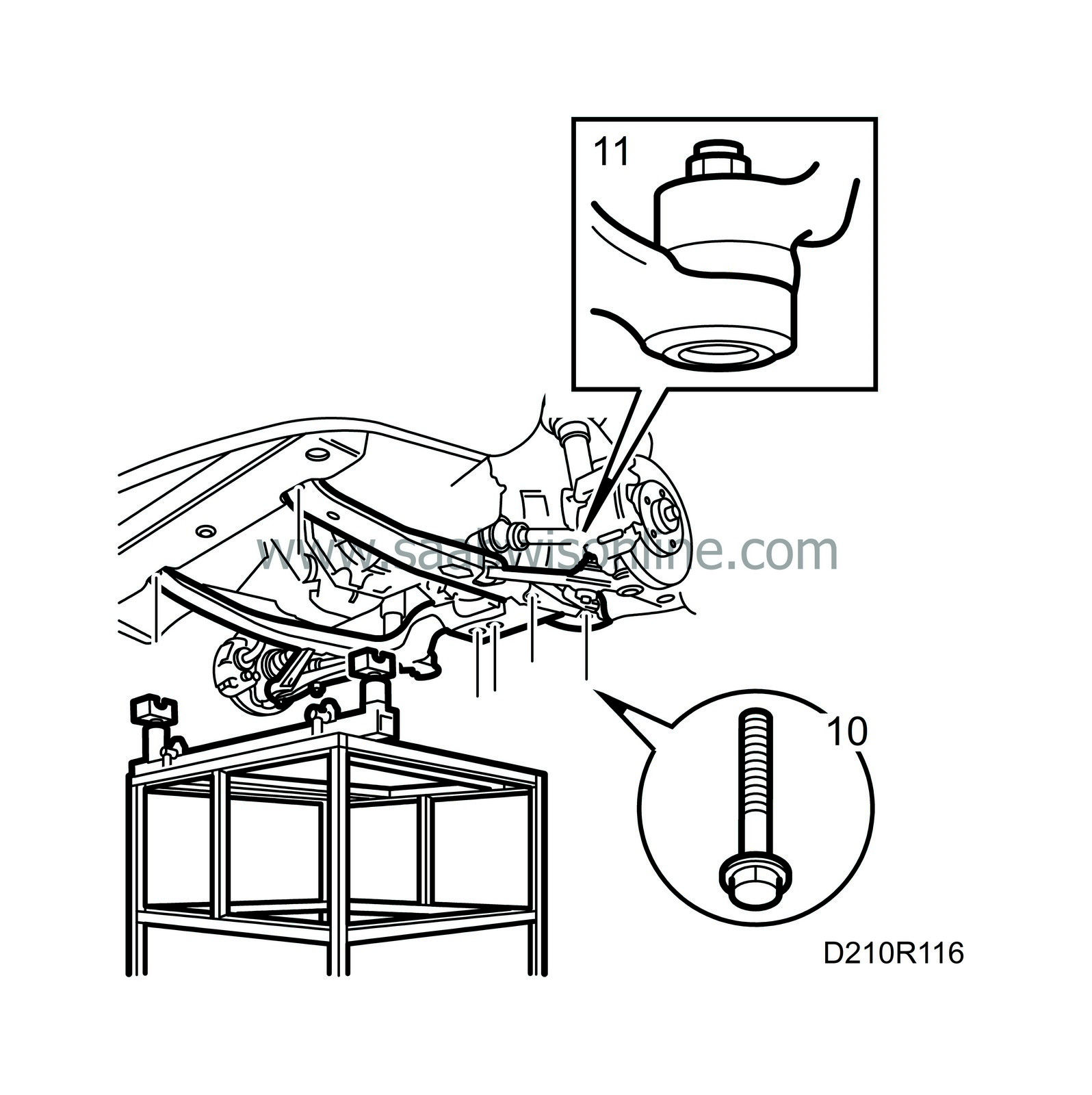
Tightening torques:
Front: 115 Nm (85 lbf ft)
Centre: 190 Nm (140.6 lbf ft)
Rear: 110 Nm + 75˚ (81.4 lbf ft + 75˚)
|
|
11.
|
Fit and tighten the end piece nuts.
Tightening torque: 75 Nm (55.5 lbf ft)
|
|
12.
|
Clean the area for the joint in the exhaust pipe.
|
|
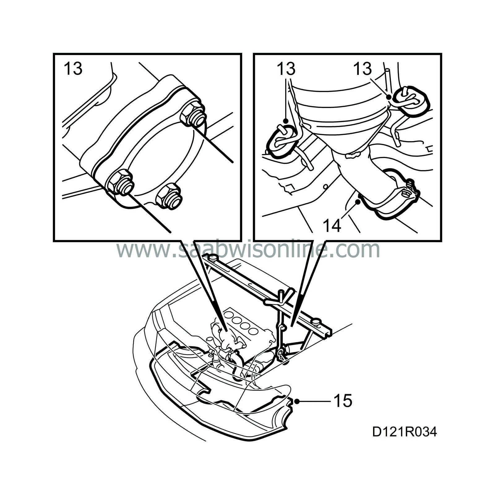
13.
|
Fit the front exhaust pipe. Lubricate the stud on the turbocharger with Molycote 1000 before fitting.
|
|
14.
|
Screw together the joint between the front and intermediate exhaust pipes.
|
|
15.
|
Fit the air shields and wheels.
Tightening torques:
Wheels: 120 Nm (89 lbf ft)
|
|
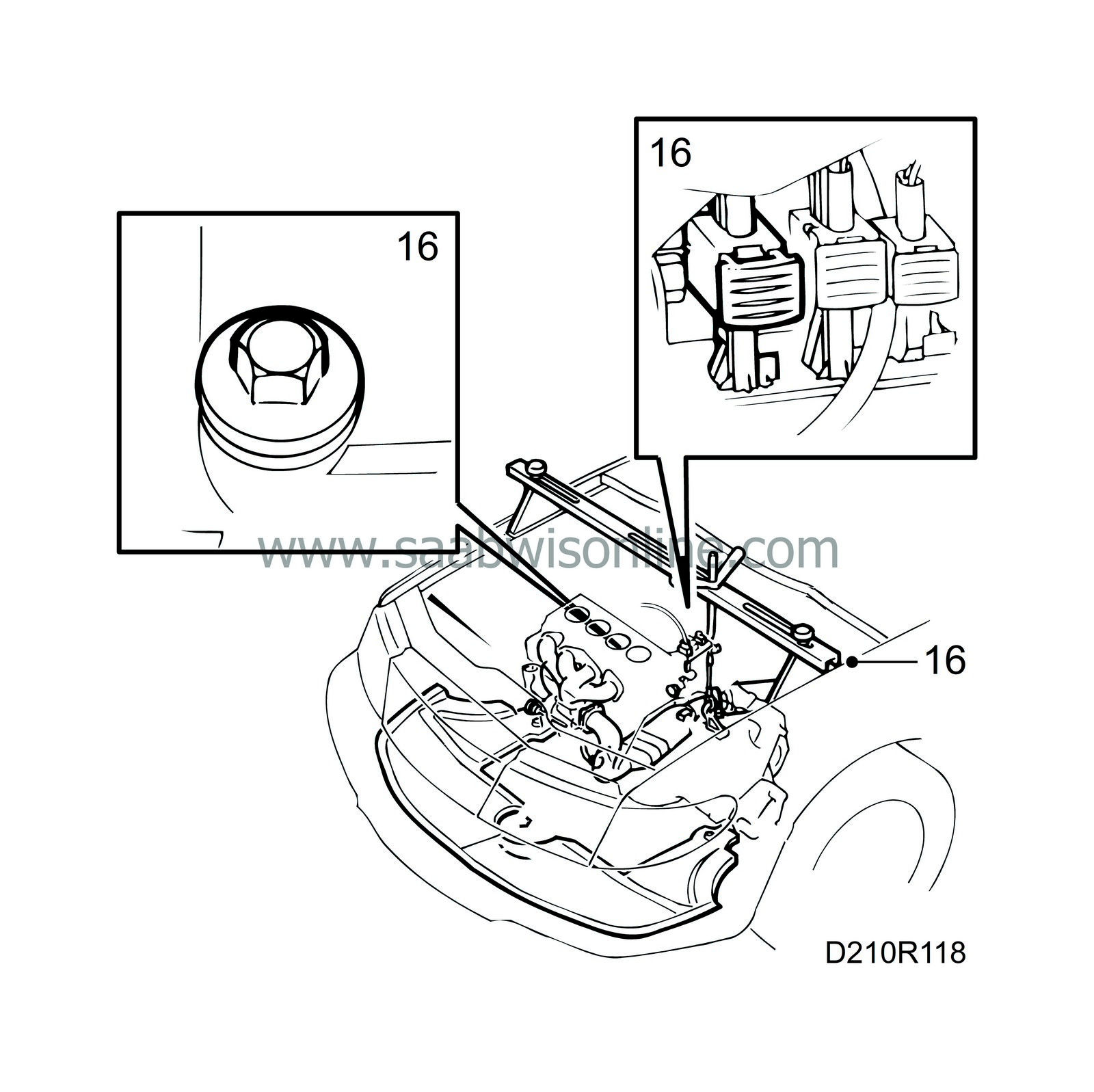
16.
|
Make sure the oil drain plug is tight, lower the car and fill with engine oil. Replace the dipstick, connect the oxygen sensor cable and remove the lifting beam
|


